
Related Manuals for Comelit HUB32LCD


Summary of Contents for Comelit HUB32LCD
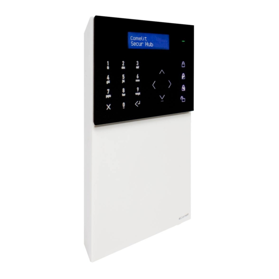
- Page 1 TECHNICAL MANUAL Quick installation manual for wireless intruder alarm control panel HUB32LCD Passion.Technology.Design.
-
Page 2: Table Of Contents
Index Index ....................2 Available documentation ..............3 System overview ................3 System technical specifi cations .............4 Product range .................. 5 Package Contents ................5 Description of the control panel ............ 6 Installing the control panel ............. 6 Removing the backplate ................6 Installing the LAN module ...............7 Installing the 2G/3G module ..............7 Replacing the backplate ................7... -
Page 3: Available Documentation
System overview Comelit art. HUB32LCD is a wireless intruder alarm control panel for use in residential applications and in small- and medium- sized commercial applications. It has a 16 x 2-character display and a Capsense keypad which allows rapid navigation of the installer and user menus. -
Page 4: System Technical Specifi Cations
Yes, micro-SD (MAX. 32 GB) IP camera recording 4 cameras @ 5fps, 384 kbps, HD CCTV technical specifi cations Live cameras 16 (viewing via Comelit app) GSM/GPRS channel 2G or 3G module SIM card Micro-SIM (not included) TCP-IP channel Built-in... -
Page 5: Product Range
Product range Comelit code Description HUB32LCD 32-ZONE RADIO CONTROL PANEL, LCD INTERFACE, IP (Wi-Fi & LAN) HUB2G 2G MODULE FOR HUB RADIO CONTROL PANEL HUB3G 3G MODULE FOR HUB RADIO CONTROL PANEL RF4KEY 4-BUTTON REMOTE CONTROL RFPA RADIO PANIC BUTTON... -
Page 6: Description Of The Control Panel
Description of the control panel 1. LCD/CAP-SENSE front panel 7. 2G/3G module connector 2. Microphone 8. Tamper switch 3. Micro USB connectors 9. RJ45 Ethernet connector 4. Battery 10. Wired I/O terminal block 5. Battery connector 11. A/C supply terminal block 6. -
Page 7: Installing The Lan Module
Installing the LAN module Installing the 2G/3G module Replacing the backplate... -
Page 8: Choosing The Correct Mounting Position
Choosing the correct mounting position When choosing the correct mounting position for the control panel, take the following factors into account. Functional factors: • When the control panel is on and running, a wireless network is generated: avoid fi tting the control panel near sources of RF electromagnetic disturbance, such as large electrical appliances or air conditioners. -
Page 9: Installing The Wall Mounting Backplates
Installing the wall mounting backplates Installing the desk base... -
Page 10: The Front Panel
The front panel 1. 16 x 2-character LCD. 2. LED indicators: green, orange, red. 3. Alphanumeric keypad. 4. Arming/disarming buttons. 5. Back/Cancel/Delete button. 6. Enter/Confi rm button. 7. Navigation keypad / menu button. • Green LED: indicates the system is armed (lit steadily) or in “not ready to arm” condition (fl ashing). The LED is off if the system is ready for arming. -
Page 11: Installation Wizard
Installation Wizard The installation wizard is a guided step-by-step procedure which can be used to set the main parameters required to start up a basic system and get it running. Each step of the procedure is used to set a group of specifi c parameters. The installation wizard starts automatically after the language is selected, but can be accessed at any time as the fi... -
Page 12: Set Rf Zones
Set RF zones? The sixth step in the installation wizard is used to register RF detectors. 1. Enter the menu by pressing Enter/Confi rm. 2. Select the zone to be registered using the navigation keypad and confi rm by pressing Enter/Confi rm. »... -
Page 13: Connect To App
Connect to APP? The tenth step in the installation wizard is used to register accounts relating to the Comelit app on the control panel. 1. Enter the menu by pressing Enter/Confi rm. » The control panel shows the list of App - IDs, showing the text “Available” for the free IDs. When the request for a free slot is confi... -
Page 14: Service
Service Accessing the Installer menu The Installer menu contains all the options required to confi gure the system. Please refer to the programming manual for information regarding all the options in the installer menu. To access the Installer menu: Enter the installer code (default 001961) using the alphanumeric keypad and press the down arrow. Activating the installation wizard To activate the installation wizard: 1. -
Page 15: Consult Event Log
Consult event log Use this function to consult the event log. The control panel can log up to 1024 events. New events are stored in the log as event 0000. Event 1023 becomes 1024 and is then deleted from the log. To consult the log: 1. - Page 16 CERTIFIED MANAGEMENT SYSTEMS w w w . c o m e l i t g r o u p . c o m Via Don Arrigoni, 5 - 24020 Rovetta (BG) - Italy...