Advertisement
Quick Links
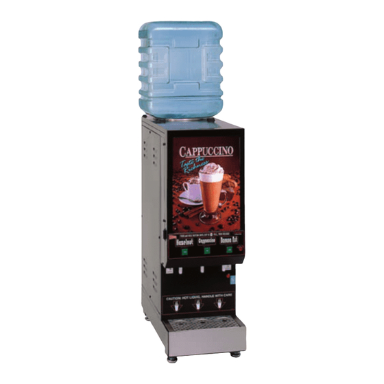
CAPPUCCINO, COFFEE, and SOUP DISPENSERS
Cecilware sells value... Worldwide
45 -05 20th Avenue, Long Island City, NY 11105
GB POUROVER
•GB1P
•GB2P
•GB3P
•GB4P
OPERATION MANUAL
• Specifications
• Installation and Operating Instructions
• Adjustments
• Test & Troubleshooting
• Maintenance
• Cleaning and Sanitizing
• Parts Identification & Illustration
• Wiring Diagrams
•
718-932-1414
FAX
718-932-7860
models:
NI52A-C 12/5/2005
2
3
4
8
9
10
11
14
Advertisement

Related Manuals for Cecilware GB1P


Summary of Contents for Cecilware GB1P
- Page 1 CAPPUCCINO, COFFEE, and SOUP DISPENSERS Cecilware sells value... Worldwide 45 -05 20th Avenue, Long Island City, NY 11105 GB POUROVER •GB1P •GB2P •GB3P •GB4P OPERATION MANUAL • Specifications • Installation and Operating Instructions • Adjustments • Test & Troubleshooting • Maintenance •...
- Page 2 Model No. Volts GB1P, GB2P, GB3P 120V GB4P GB1P, GB2P, GB3P, 120/240V GB4P 240V 120V, 1.8 KW, 15A, Nema 5-15R standard on all models; 3.0 KW, 120/240V units available ** 120/240V, 3 pole, 4 wire grounding type Twist-Plug Receptacle. For 240V units, Use L6-20R, 2 pole, 3 Wire Twist-Plug Receptacle.
- Page 3 START UP INSTRUCTIONS FOR GB POUROVER CAPPUCCINO DISPENSER (see illustration 9-3 for clarification) I. INSTALLATION INSTRUCTIONS This equipment is to be installed to comply with the applicable Federal, State, or local plumbing codes having jurisdiction. In addition: 1. A quick disconnect water connection or enough extra coiled tubing (at least 2x the depth of the unit) so that the machine can be moved for cleaning underneath.
- Page 4 III. PRIMING - AUTOFILL - Water Selection Switch - Toggle Down (See Back Panel) 1. Plug into power outlet. 2. Turn Heater Switch ON. 3. Allow 10 to 15 minutes for water to reach dispense temperature of 185°F. Heater Indicator Light (red) goes ON when heater is on (see lower front panel). 4.
- Page 5 HOPPER COVER CD106 AUGER GEAR – FOR RECTANGULAR HOPPERS: CD117 [Used With Nylon Auger CD130] CD117 [Used With Wire Auger CD101 &CD130] FRONT BUSHING: Rectangular Hoppers: CD277 [ Ø22.5 mm ] CD306 [ Ø17 mm ] Square Hoppers: CD102 [ Ø22.5 mm w/O-Ring CD103] CD131 [ Ø22.5 mm w/O Ring] AUGERS: CD130 Nylon Auger [Ø22.5 mm X 17mm Pitch w/O-Ring CD139]...
- Page 6 DRINK SIZE ADJUSTMENTS (OPTIONAL FEATURE) a. Manual Dispense Machines: Hold down the Dispense Button until desired amount is dispensed. b. Automatic Machines with Programmable "Teach me" Timers [L576A or L582A]: The timer is programmable from the dispense button. Programming For Automatic Dispense 1.
- Page 7 TEST A) Water Inlet Valve Test Turn power off. If the water level rises inside the tank, the Water Inlet Valve is leaking. Disconnect wires from the Water Inlet Valve coil and connect a 2 wire line cord to the terminals. Plug it into a 115V outlet. If water flows in and stops when you pull it out, the Valve is working fine.
- Page 8 TROUBLESHOOTING GUIDE FOR GB-POUROVER WARNING: To reduce the risk of electrical shock unplug the dispenser power cord before repairing or replacing any internal components of the unit.. Before any attempt to replace a component be sure to check all electrical connections for proper contact.
- Page 9 MAINTENANCE To Replace The Picture / Duratran GB w/ Metal Doors Only: Lift up the two end tabs on top of door with a pointed object or flat head screwdriver. Pull the entire picture frame out. Open up the two clear panels and replace picture.
-
Page 10: Cleaning And Sanitizing
CLEANING AND SANITIZING Sanitizing: All sanitizing agents in the food zone must comply with 21 CFR 178.1010. All food dispensing units should be sanitized periodically. All parts to be sanitized must be cleaned first. To prepare a sanitizing solution: Add 2 Tsp. Of Liquid Clorox Bleach (5.25% Concentration) To 1 gallon Of Water At Room Temperature (70°- 90°F). Note: Always start with a unopened bottle of Clorox Bleach since the solution from an opened bottle has a short life span. - Page 11 Y FOR ADJUSTING ISPENSE VALVE RESERVOIR AND TANK ASSEMBLY Q174Q RESERVOIR ASSEMBLY ITEM Q174A L499P M461A K402A P410A K535A K525A RI71A ITEM P446A G194A MO18A K537A L656A RZ53Q L467A M601A M545A M391A M455A M008A L532A DESCRIPTION P.O.-LINE TANK(GB3M/ICAP) FLOAT SWITCH 70-V-A DIRECT MOUNTING SEAL (.466 ID) LEVEL CONTROL, PROBE SEAL...
- Page 12 DESCRIPTION AND LOCATION OF COMPONENTS (GB3P SHOWN) 33 34...
- Page 13 HEATER SWITCH, 30A SPST (120V) OR / (120/240V) TOP COVER, FRONT HOPPER ASS’Y WITH NYLON AUGER / OR WITH WIRE AUGER NUT (FLANGE) AUGER MOTOR (90 RPM) SIDE PANELS GB1P GB2P M518A / M519A M518A / M519A 97128 97128 Q174Q...
- Page 14 DOOR UNIT MAIN UNIT...
- Page 15 DOOR UNIT MAIN UNIT...
- Page 16 DOOR UNIT...
- Page 17 DOOR UNIT MAIN UNIT...
- Page 18 DOOR UNIT MAIN UNIT...