
Related Manuals for FIC PT-2006


Summary of Contents for FIC PT-2006
- Page 1 PT-2006 MAINBOARD MANUAL DOC No. : 15289 Rev. : A0 Date : 7, 1996 Part No. : 25-10526-00...
-
Page 2: Handling Precautions
Notice Handling Precautions Warning : 1. Static electricity may cause damage to the integrated circuits on the mainboard. Before handling any mainboard outside of its protective packaging, ensure that there is no static electric charge in your body. 2. There is a danger of explosion if the battery is incorrectly replaced. Replace only with the same or an equivalent type recommended by the manufacturer. - Page 3 SIR support further enhance system I/O connectivity. This chapter gives a you a brief overview of the PT-2006 mainboard. In addition to basic information on the board’s main components and features, it also provides advice on how to upgrade and expand it. For updated BIOS, drivers, or...
-
Page 4: Main Features
PT-2006 Mainboard Manual Main Features The PT-2006 mainboard comes with the following high-performance features: Easy Installation Award BIOS with support for Plug and Play, auto detection of Hard Drive and IDE features, and MS Windows 95 compatible. Flexible Processor Support... - Page 5 Overview ISA & PCI Expansion Slots Three 16-bit ISA and four 32-bit non-shared PCI expansion slots provide all the room you need to install a full range of add-on cards. USB Support Onboard support for two Universal Serial Bus connectors via a plug-in connector.
-
Page 6: Package Checklist
PT-2006 Mainboard Manual Package Checklist Please check that your package contains all the items listed below. If you discover any item is damaged or missing, please contact your vendor. The PT-2006 mainboard Serial port/parallel port cables with bracket Seriall port cable with bracket... - Page 7 Overview Cables...
- Page 8 PT-2006 Mainboard Manual This User Manual This manual is designed to guide you and facilitate your use of the PT-2006 mainboard. It contains a description of the design and features of the mainboard, and also includes useful information for changing the configuration of the board and the system it is installed in.
-
Page 9: Something Interesting
Overview Something Interesting This section provides useful information that you will need to know should you decide to modify or upgrade the configuration of the mainboard and the system it is installed in. If you do not have the confidence to upgrade the mainboard yourself, we advise that you consult a qualified service technician for assistance. -
Page 10: Irq Functionality
PT-2006 Mainboard Manual IRQ Functionality As you read through this manual, you will see the term IRQ on a number of occasions. It is important for you to know what this term means, particularly if you intend to upgrade your system. -
Page 11: Dma Channels Of Isa Cards
Overview DMA Channels of ISA Cards Some Legacy and PnP ISA add-on cards may also need to use a Direct Memory Access (DMA) channel. DMA assignments for this mainboard are handled in the same way as the IRQ assignment process outlined above. For more information, please refer to Chapter 3 of this manual. -
Page 12: Serial Infrared (Sir) Connections
PT-2006 Mainboard Manual Serial Infrared (SIR) Connections This mainboard features support for highly-sophisticated SIR technology, which allows bi-directional and cordless data transactions with other IrDA compliant computers and peripheral devices using infrared as a medium. This transmission is carried out in either Full Duplex Mode or Half Duplex Mode. The former allows simultaneous data transmission and reception, while the latter disables the reception when transmission occurs. - Page 13 Overview Universal Serial Bus (USB) Functionality This mainboard features integrated support for state-of-the-art USB technology, which provides high-speed and easy-to-use Plug & Play connections to the future generation of external peripherals, such as keyboards, mouse, monitors, game devices, scanners, printers, and fax/modems. USB overcomes conventional I/O bottlenecks by combining the I/O ports into a single dual-channel connector that supports up to 120 devices.
- Page 14 PT-2006 Mainboard Manual THIS PAGE INTENTIONALLY LEFT BLANK...
-
Page 15: Installation Procedures
Chapter 2 Installation Procedures The PT-2006 has several user-adjustable jumpers on the board that allow you to configure your system to suit your requirements. This chapter contains information on the various jumper settings on your mainboard. To set up your computer, you should follow these installation steps:... -
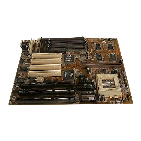
Page 16: Mainboard Layout
PT-2006 Mainboard Manual Mainboard Layout... -
Page 17: Set System Jumpers
Installation Procedures 1). Set System Jumpers Jumpers Jumpers are used to select the operation modes for your system. Some jumpers on the board have three metal pins with each pin representing a different function. To a jumper, a black cap containing metal contacts is placed over the jumper pins according to the required configuration. - Page 18 PT-2006 Mainboard Manual Clear Password: CPS This jumper allows you to set the password configuration to Enabled Disabled. You may need to enable this jumper if you forget your password. Flash ROM Type Selection: EP1, EP2, EP3 These jumpers allow you to select the flash ROM type.
-
Page 19: Install System Ram Modules
The PT-2006’s RAM is comprised of four industry standard 72-pin Single In-line Memory Modules (SIMMs) and one Dual In-line Memory Modules (DIMMs). Each SIMM socket supports from 4 to 64MB... -
Page 20: Ram Module Configuration
PT-2006 Mainboard Manual RAM Module Configuration SIMMs and DIMMs in Bank 0 and Bank 1 can be installed in many combinations. Some of them are listed in the following table. (Unit : MB) TOTAL SIMM SIMM MEMORY (Bank 0) (Bank 1) (Bank 1 4 &... -
Page 21: Install Simms
Installation Procedures Install SIMMs Complete the following procedures to install SIMMs: CAUTION : Always turn the system power off before installing or removing any device; and see “Handling Precautions” at the start of this manual. 1. Locate the SIMM slots on the mainboard. (See figure below.) NOTE : SIMMs in each bank must be of the same type;... -
Page 22: Install Dimms
PT-2006 Mainboard Manual Install DIMMs Complete the following procedures to install DIMMs: 1. Locate the DIMM slots on the mainboard. (See figure below.) Install the DIMM straight down into the DIMM slot with both hands. The clips of the slot will close up to hold the DIMM in place when the DIMM touches the slot’s bottom. -
Page 23: Cache Memory
SRAM module slot which allows you to expand the cache RAM size. The specification of the cache SRAM module requires Intel Coast. Standard version 3.X, such as FIC PB512K-3.0. Please note that for 256K secondary cache, M2 and M3 should be mounted with 32Kx32 Pipeline Burst SRAM. - Page 24 PT-2006 Mainboard Manual 256/512KB Cache SRAM (Onboard) NOTE : Use the correct chips for the amount of cache memory you want to add. Install both the correct Cache and Tag SRAM.
- Page 25 Installation Procedures 512KB Cache RAM (Onboard and SRAM Module) 256/512KB Cache RAMh (SRAM Module)
-
Page 26: Install The Cpu
PT-2006 Mainboard Manual 3). Install the CPU The CPU module resides in the Zero Insertion Force (ZIF) socket on the mainboard. CAUTION : Always turn the system power off before installing or removing any device. Always observe static electricity precautions. - Page 27 Installation Procedures CPU External Clock (BUS) Frequency: CLK1, CLK2 The table below shows the jumper settings for the different CPU speed configurations. CPU to Bus Frequency Ratio:FREQ1 and FREQ2 These two jumpers are used in combination to decide the ratio of internal frequency of the CPU to bus clock.
- Page 28 PT-2006 Mainboard Manual Intel Pentium CPUs Frequency...
- Page 29 Installation Procedures Voltage...
- Page 30 PT-2006 Mainboard Manual AMD-K5 CPUs Frequency NOTE : * This CPU had not yet been tested when this manual was printed.
- Page 31 Installation Procedures Voltage...
- Page 32 PT-2006 Mainboard Manual Cyrix 6x86 CPUs Frequency NOTE : * This CPU had not been tested when this manual was printed.
- Page 33 Installation Procedures Voltage...
-
Page 34: Ibm 6X86 Cpus
PT-2006 Mainboard Manual IBM 6x86 CPUs Frequency NOTE : * This CPU had not been tested when this manual was printed. - Page 35 Installation Procedures Voltage...
-
Page 36: Install Expansion Cards
PT-2006 Mainboard Manual 4). Install Expansion Cards Your PT-2006 features three 16-bit ISA Bus and four 32-bit PCI Bus expansion slots. This section describes how to connect an expansion card to one of your system’s expansion slots. Expansion cards are printed... -
Page 37: Connect Cables And Power Supply
Installation Procedures 5). Connect Cables and Power Supply Keyboard Connector: AT_KB The cable of your 101-key enhanced keyboard or 106-key Windows 95 keyboard is plugged into this connector. Serial Port Connectors: COM1, COM2 These two connectors allow you to connect with your devices that take serial ports, such as a serial mouse or a modem. - Page 38 PT-2006 Mainboard Manual CPU Fan Connector: FAN This connector is linked to the CPU fan for cooling the processor temperature. Floppy Diskette Drive Connector: FLOPPY This connector provides the connection with your floppy disk drive. Front Panel Block Connector: F_PNL...
- Page 39 Installation Procedures This block connector concludes : PW_LED, KB_LOCK, TB_LED, SP_SW, SPK, SP_LED, IDE_LED, RPW_SW, and RST connectors. Item Connector Pin Type Feature PW_LED 2-pin male indicates the system power status KB_LOCK 2-pin male allows the keyboard to access the system TB_LED 2-pin male...
- Page 40 PT-2006 Mainboard Manual Infrared Connector: IR This connector supports the connection to your IR device. The IR port uses the same IRQ as COM2 port, therefore you need to adjust this BIOS option when an IR device is installed. Standard Power Supply Connector: POWER This 12-pin block connector is used for connecting to the standard 5V power supply.
-
Page 41: Printer Connector: Printer
Installation Procedures IDE HDD Device Connectors: PRIMARY, SECONDARY These two connectors are used for your IDE hard disks. If you have one IDE hard disk, connect it to the PRIMARY connector using the IDE HDD flat cable provided with the mainboard. The BIOS auto detection sets it to be a “ Primary Master”... - Page 42 PT-2006 Mainboard Manual Remote Power Supply Connector: RPW_CON This 3-pin male connector allows you to enable (or disable) the system power if the RPW_SW is on (or off). Universal Serial Bus Connectors: USB1, USB2 These two connectors link with USB peripheral devices via an optional USB riser card.
-
Page 43: Award Bios Setup
Chapter 3 Award BIOS Setup The PT-2006 comes with the Award BIOS chip that contains the ROM Setup information of your system. This chip serves as an interface between the processor and the rest of the mainboard’s components. This chapter explains the information contained in the Setup program and tells you how to modify the settings according to your system configuration. -
Page 44: Standard Cmos Setup
PT-2006 Mainboard Manual Standard CMOS Setup The Standard CMOS Setup screen is displayed above. Each item may have one or more option settings. The system BIOS automatically detects memory size, thus no changes are necessary. Use the arrow keys to highlight the item and then use the <<PgUp>>... - Page 45 Award BIOS Setup LANDZ: The cylinder number that the disk drive heads (read/write) are seated when the disk drive is parked. SECTOR: The sector number of each track defined on the hard disk. The range is from 1 to MODE: Select Auto to detect the mode type automatically.
-
Page 46: Bios Features Setup
PT-2006 Mainboard Manual BIOS Features Setup Moving around the BIOS Features Setup program shown above works the same way as moving around the Standard CMOS Setup program. Users are not encouraged to run the BIOS Features Setup program. Your system should have been fine-tuned before shipping. - Page 47 Award BIOS Setup Boot Sequence Allows the system BIOS to first try to boot the operating system from the selected disk drive. The options are: A, C (Default); C, A; C, CDROM, A; CDROM, C, A. Swap Floppy Drive Allows you to switch the order in which the operating system accesses the floppy drives during boot up.
- Page 48 PT-2006 Mainboard Manual Sets the delay time before a character is repeated. The options are: 250 (Default), 500, 750, 1000 millisecond. Security Option Allows you to set the security level of the system. The options are: Setup (Default), System. PS/2 Mouse Function Control When enabled, allows you to release IRQ12 for using the PS/2 mouse.
-
Page 49: Chipset Features Setup
Award BIOS Setup Chipset Features Setup Auto Configuration When set at Enabled, it allows you to configure the features that from the third one, Fast RAS To CAS Delay, to the eighth one, Refresh RAS# Assertion. This is for technician use only. The options are: Enabled (Default), Disabled. - Page 50 PT-2006 Mainboard Manual RAM Write Burst Timing Allows you to define DRAM write burst timing. This is for technician use only. The options are: X-3-3-3, X-2-2-2 (Default), X-4-4-4. Fast MA to RAS# Delay CLK Allows you to select the clock of the memory address (MA) to RAS# delay.
- Page 51 Award BIOS Setup 8 Bit I/O Recovery Time Allows you to set the 8-bit ISA I/O recovery time. This is for technician use only. The options are: 1 (Default), 2, 3, 4, 5, 6, 7, 8. Unit: Bus clock. 16 Bit I/O Recovery Time Allows you to set the 16-bit ISA I/O recovery time.
-
Page 52: Power Management Setup
PT-2006 Mainboard Manual Power Management Setup Power Management This item allows you to adjust the power management features. Select Disable for disabling global power management features. Select User Defined for configuring your own power management features. MIN Saving initiates all predefined timers in their minimum values. MAX Saving, on the other hand, initiates maximum values. - Page 53 Award BIOS Setup Video Off Method The option V/H SYNC+Blank allows the BIOS to blank off screen display by turning off the V-Sync and H-Sync signals sent from add-on VGA card. DPMS Supported allows the BIOS to blank off screen display by your add- on VGA cardhich supports DPMS (Display Power Management Signaling function).
- Page 54 PT-2006 Mainboard Manual Selecting OFF allows the BIOS to refrain from waking up the system. Selecting ON allows the BIOS to wake up the system from Doze mode, Standby mode, or Suspend mode. The options are: OFF, ON. The default of IRQ3, 4, 12 (Wake-Up Event): ON.
-
Page 55: Pnp/Pci Configuration Setup
Award BIOS Setup PNP/PCI Configuration Setup PNP OS Installed If your operating system is a Plug-and-Play one, such as Windows NT, Windows 95, select Yes. The options are: No (Default), Yes. Resources Controlled By If you set at Auto, the BIOS automatically arranges all system resources for you. -
Page 56: Load Bios Defaults
PT-2006 Mainboard Manual Load BIOS Defaults BIOS defaults contain the most appropriate values of the system parameters that allow minimum system performance. The OEM manufacturer may change the defaults through MODBIN before the binary image burns into the ROM. Load Setup Defaults Selecting this field loads the factory defaults for BIOS and Chipset Features which the system automatically detects. -
Page 57: Integrated Peripherals
Award BIOS Setup Integrated Peripherals IDE HDD Block Mode When enabled, allows the system to execute read/write requests to hard disk in block mode. The options are: Enabled (Default), Disabled. IDE Primary Master PIO Allows an automatic or a manual configuration of the PCI primary IDE hard disk (master) mode. - Page 58 PT-2006 Mainboard Manual On-Chip Primary PCI IDE When enabled, allows you to use the onboard primary PCI IDE. The available options are: Enabled (Default), Disabled. On-Chip Secondary PCI IDE When enabled, allows you to use the onboard secondary PCI IDE.
- Page 59 Award BIOS Setup This feature allows you to select the infrared data transaction way. The options are: Half (Default), Full, HPKIR, ASKIR. RxD , TxD Active The feature allows you to select the active signals of the reception end and the transmission end.
- Page 60 PT-2006 Mainboard Manual Supervisor/User Password To enable the Supervisor/User passwords, select the item from the Standard CMOS Setup. You will be prompted to create your own password. Type your password up to eight characters and press <<Enter>>. You will be asked to confirm the password.
-
Page 61: Save And Exit Setup
Award BIOS Setup Save and Exit Setup After you have made changes under Setup, press <<Esc>> to return to the main menu. Move cursor to Save and Exit Setup or press F10 and then press Y to change the CMOS Setup. If you did not change anything, press <<Esc>> again or move cursor to Exit Without Saving and press Y to retain the Setup settings.