Advertisement
Quick Links
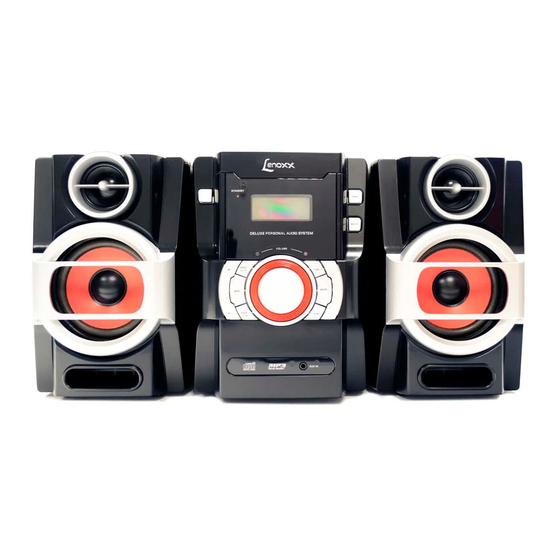
Model: MC-261
CONTENTS
PAGE
Specifications ..................................................................................................................... 2-4
Block Diagram ................................................................................................................................................5
Safety Checks ................................................................................................................................................6
Wiring Diagrams...................................................................................................................... 7
Schematic Diagrams............................................................................................................. 8-10
Printed Circuit Boards.......................................................................................................... 11-12
Exploded View..............................................................................................................................................13
Advertisement

Summary of Contents for Lenoxx MC-261
-
Page 1: Table Of Contents
Model: MC-261 CONTENTS PAGE Specifications ……………………………………………………………………………………………………... 2-4 Block Diagram ..............................5 Safety Checks ..............................6 Wiring Diagrams………………………………………………………………………………………………………. 7 Schematic Diagrams……………………………………………………………………………………...……..8-10 Printed Circuit Boards………………………………………………..………………………..…………..….… 11-12 Exploded View..............................13... - Page 3 — Full load burn-in...
- Page 4 300MV(Input) 300MV(Input) 10%T.H.D Power O/P Stereo Separation 180MV(Input) 180MV(Input) Min Hum Max Hum Total Harmonic Distortion...
-
Page 5: Block Diagram
BLOCK DIAGRAM... -
Page 6: Safety Checks
SAFETY CHECKS Important Note!!! Do the following safety checks after servicing this unit. 1. Remove all the externally connected test equipment and wires before testing the unit. 2. Use the safety test circuit as shown below. 3. Plug the power cord or unit to be tested into the test receptacle. 4. -
Page 7: Wiring Diagrams
WIRING DIAGRAMS... -
Page 8: Schematic Diagrams
SCHEMATIC DIAGRAMS... - Page 9 SCHEMATIC DIAGRAMS...
- Page 10 SCHEMATIC DIAGRAMS...
-
Page 11: Printed Circuit Boards
PRINTED CIRCUIT BOARDS... - Page 12 PRINTED CIRCUIT BOARDS...


