Table of Contents
Advertisement
Quick Links
TPRG SERIES
INSTALLATION INSTRUCTIONS
Single Package Heat Pump - Single Stage, R-410A
It is your responsibility to know this product better than your customer. This includes being
able to install the product according to strict safety guidelines and instructing the customer on
how to operate and maintain the equipment for the life of the product. Safety should always be
the deciding factor when installing this product and using common sense plays an important
role as well. Pay attention to all safety warnings and any other special notes highlighted in the
manual. Improper installation of the furnace or failure to follow safety warnings could result
in serious injury, death, or property damage.
These instructions are primarily intended to assist qualified individuals experienced in the
proper installation of this appliance. Some local codes require licensed installation/service
personnel for this type of equipment. Please read all instructions carefully before starting the
installation. Return these instructions to the customer's package for future reference.
DO NOT DESTROY. PLEASE READ CAREFULLY AND KEEP IN A SAFE PLACE FOR FUTURE REFERENCE.
IMPORTANT
ATTENTION INSTALLERS:
13 SEER
Advertisement
Table of Contents

Related Manuals for Heat Controller TPRG Series


Summary of Contents for Heat Controller TPRG Series
- Page 1 TPRG SERIES 13 SEER INSTALLATION INSTRUCTIONS Single Package Heat Pump - Single Stage, R-410A IMPORTANT ATTENTION INSTALLERS: It is your responsibility to know this product better than your customer. This includes being able to install the product according to strict safety guidelines and instructing the customer on how to operate and maintain the equipment for the life of the product.
-
Page 2: Table Of Contents
TAbLE OF CONTENTS IMPORTANT SAFETY INFORMATION .......3 STARTUP & ADjUSTMENTS ........10 Pre - Start Checklist ..........10 REqUIREMENTS & CODES ........4 Start - Up Procedure ..........10 GENERAL INFORMATION ..........4 Air Circulation ............10 Before You Install this Unit .........4 System Heating ............10 Locating the Heat pump ...........4 System Cooling ............10 Minimum Clearances ..........5... -
Page 3: Important Safety Information
IMPORTANT SAFETY INFORMATION WARNING: Please read all instructions before servicing this equipment. Pay attention to all safety warnings and any other special PROPOSITION 65 WARNING: This product notes highlighted in the manual. Safety markings are contains fiberglass wool, a product known used frequently throughout this manual to designate a to the state of California to cause cancer. -
Page 4: Requirements & Codes
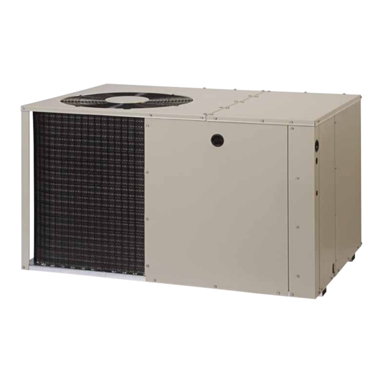
• Use caution when handling this appliance or removing GENERAL INFORMATION components. Personal injury can occur from sharp metal Single packaged heat pumps are ready for easy and edges present in all sheet metal constructed equipment. immediate installation and can be readily connected into the high static duct system of a home. -
Page 5: Minimum Clearances
Minimum Clearances HEAT PUMP INSTALLATION Minimum clearances MUST be maintained from adjacent Unpacking the Unit structures to provide room for proper servicing and air It is recommended that the unit be unpacked at the circulation. DO NOT install unit in a confined or recessed installation site to minimize damage due to handling. -
Page 6: Locating & Installing The Supply Dampers
SINGLE DUCT APPLICATION MULTIPLE DUCT APPLICATION Figure 2. Typical Duct Applications Locating & Installing the Supply Damper(s) When locating the supply damper(s), carefully check floor joists and frame members that could interfere with the installation of the damper or flexible duct. Ideally, the damper (Figure 4) should be located in the bottom of the main duct, forward of center of the home, at least three feet from the nearest register. -
Page 7: Electrical Connections
• Use only copper wire for the line voltage power supply to this unit as listed in Table 1. Use proper code agency Elbow listed conduit and a conduit connector for connecting the supply wires to the unit. Use of rain tight conduit is recommended. -
Page 8: Overcurrent Protection
Overcurrent Protection as southern Arizona. The factory time interval setting is 30 minutes. Overcurrent protection must be provided at the branch circuit distribution panel and sized as shown on the unit Defrost Control board rating label and according to applicable local codes. Operational Information Generally, the best fuse or breaker for any heat pump •... -
Page 9: Speed Up Mode (Testing Procedure)
• Select the correct size heat package for the installation. Speed Up Mode (Testing Procedure) See specifications sheet for available kits and application. 1. Jumper T2 to DFT at the test terminals. Install the heater kit according to the to the installation 2. -
Page 10: Startup & Adjustments
6. Verify the duct work has no air leaks. CAUTION: 7. Verify the condensate drain is installed correctly and functions properly. Label all wires prior to disconnection when 8. Set the temperature mode above room temperature. servicing controls. Wiring errors can cause The unit should stop. -
Page 11: Adjustment Of Refrigerant Charge
Cooling Mode If the discharge pressure rises above 650 psig, the switch will open and de-energize the unit. The switch When the TEST pins are shorted together for more than will close again once the discharge pressure decreases 1 second, the Anti Short Cycle Timer will be bypassed. to 460 psig. -
Page 12: Figures & Tables
FIGURES & TAbLES Top View Electric Heater Power Supply Power Supply Low Voltage Supply Control Blower Access Panel Access Side View 17.86 Panel 15.36 10.10 1" 3/4" NPT Drain Connection 1.38 18.01 3.2 5.29 12.13 Back (Duct) View 9.15 1" 3.15 17.50 9.04... -
Page 13: Charging Tables - Cooling Mode
REFRIGERANT CHARGING TAbLES - COOLING MODE Shaded boxes indicate flooded conditions. Rated design values are based on rated indoor air flow and 80 °F entering dry bulb. 1. Suction pressure will vary according to variations in indoor conditions. 2 All pressures are listed psig and all temperatures in °F 3. - Page 14 REFRIGERANT CHARGING TAbLES - COOLING MODE Shaded boxes indicate flooded conditions. Rated design values are based on rated indoor air flow and 80 °F entering dry bulb. 1. Suction pressure will vary according to variations in indoor conditions. 2 All pressures are listed psig and all temperatures in °F 3.
- Page 15 REFRIGERANT CHARGING TAbLES - COOLING MODE Shaded boxes indicate flooded conditions. Rated design values are based on rated indoor air flow and 80 °F entering dry bulb. 1. Suction pressure will vary according to variations in indoor conditions. 2 All pressures are listed psig and all temperatures in °F 3.
-
Page 19: Electrical Diagrams
ELECTRICAL DIAGRAMS Figure 8. Wiring Diagram - 2 & 2.5 Ton Models... - Page 20 Figure 9. Wiring Diagram - 3 Ton Models...
- Page 21 Figure 10. Wiring Diagram - 3.5, 4, & 5 Ton Models...
- Page 22 INDOOR Outdoor DEFROST Thermostat T-STAT Green (Factory Option) BOARD SUB-BASE Brown Orange Accessory Brown wire not present when Heat Plug optional thermostat us used. Typical Wiring (Field Supplied) for 1-Stage Cool, 1 Stage Electric Heat INDOOR T-STAT SUB-BASE Green DEFROST BOARD Outdoor Thermostat (Factory Option)
-
Page 24: Installation / Performance Checklist
INSTALLATION / PERFORMANCE CHECK LIST REFRIGERATION SYSTEM INSTALLATION ADDRESS: Was unit given 24 hr warm up period for crankcase heaters (if applicable)? CITY ________________________ STATE ________________ UNIT MODEL # ________________________________________ Stage-1 Liquid Pressure (high side) ________________________ UNIT SERIAL # ________________________________________ Stage-1 Suction Pressure (low side) ________________________ Unit Installed Minimum clearances per Figure 1 (page 4)?