ESI Access 5D Thermal Reader Administration Manual
Hide thumbs
Also See for Access 5D Thermal Reader:

Related Manuals for ESI Access 5D Thermal Reader

Summary of Contents for ESI Access 5D Thermal Reader
- Page 1 5D Access Thermal Reader Administration Guide This guide is for Administrators who need to prepare for, configure and operate the 5D Access Thermal Reader. Page 1 of 106 0455-0271 Rev A...
-
Page 2: Table Of Contents
Contents 1 Application Scope of the Manual ___________________________________________ 7 2 Product Overview __________________________________________________________ 7 3 Product Appearance ________________________________________________________ 8 4 Product Installation ______________________________________________________ 9 5 Local Operations __________________________________________________________ 9 Initial Interface ___________________________________________________________ 9 Main Interface _____________________________________________________________ 10 Ad Mode ____________________________________________________________________ 13 Mask/Temperature Measurement Interface _____________________________________ 14 Activation Config... - Page 3 6.3.4 Intelligent _____________________________________________________________________ 76 6.3.5 Events __________________________________________________________________________ 93 6.3.6 Storage _________________________________________________________________________ 98 6.3.7 Security ________________________________________________________________________ 99 6.3.8 System _________________________________________________________________________ 101 7 Live View _______________________________________________________________ 104 8 FAQs ____________________________________________________________________ 106 Page 3 of 106 0455-0271 Rev A...
- Page 4 Estech Systems, Inc. (ESI) shall not under any circumstances be liable for any special, consequential, incidental or indirect damages arising from the use of this manual or Estech Systems, Inc. (ESI)'s product, including but not limited to any loss of commercial profits, losses caused by missing data or documents, and anomalies during product running or information leakage due to cyber-attacks, hacker attacks, or virus attacks.
- Page 5 • Estech Systems, Inc. (ESI) (hereinafter referred to as "ESI") reserves the right to modify the content in this manual without prior notice or prompt, but ESI does not ensure that this manual is completely error- free. Subject to uncertain factors such as the physical environment, actual values of data may differ from the •...
- Page 6 Symbol Description Contains important safety instructions and indicates situations that could WARNING! cause bodily injury. Be careful. Improper operation may cause damage or malfunction to product. CAUTION! Means useful or supplemental information about the use of product. NOTE! Page 6 of 106 0455-0271 Rev A...
-
Page 7: Application Scope Of The Manual
1 Application Scope of the Manual Table1-1 Application Scope of the Manual Name 5D Access Thermal Reader with Thermal Detection Module 2 Product Overview The 5D Access Thermal Reader is a face recognition access control product featuring high performance and high reliability. The face recognition technology is perfectly integrated into the access control device, which relies on deep learning algorithms to support face authentication in order to open the door and achieve precise control of human movement in and out of secured areas. -
Page 8: Product Appearance
3 Product Appearance 1.Light supplement lamp 1 2.Camera 1 3. Infrared light supplement lamp 4.Camera 2 5.Light supplement lamp 2 6.Display screen 7. Pass-through indicator 8.Microphone 9. Card reading area 10.Loudspeaker 11.Reset 12.USB2.0 13.Network interface 14. Power input (DC 12V±25%) 15.20-pin interface 16.Tamper proof button Page 8 of 106... -
Page 9: Product Installation
4 Product Installation Please reference the 5D Access Thermal Reader Install guide. Reference the Digital Thermal Detection Module Install Guide if installing the optional Thermal Detection Module. 5 Local Operations 5.1 Initial Interface When the Access Control Terminal is used for the first time or the factory defaults are restored, users need to set the activation password, which is used to log in to the “Activation Config”... -
Page 10: Main Interface
5.2 Main Interface Figure5-2 Main Interface (Video Intercom Mode) Description Displays the current date, time, and connection status of different services. Indicates the following items from left to right: Whether to enable the face scan mode Whether an ID card reader is connected properly ... - Page 11 • Total:Total number of detected people • Normal:Number of people with normal temperature This interface is only displayed when the temperature measurement function is enabled. For detailed operation descriptions, see Advanced Setting. Displays the photo and name of an identified person in the library. Refer to “Display”...
- Page 12 Figure5-3 Main Interface (Common Access Control Mode) NOTE! The main interface does not support Call or QR code based door opening in the common access control mode. The GUI displays the recognition result of only a single person. Page 12 of 106 0455-0271 Rev A...
-
Page 13: Ad Mode
5.3 Ad Mode The 5D Access Thermal Reader supports Ads (three pictures at most). For the Ad configuration, see "Ad Mode". Figure5-4 Ad Interface In Ad Mode, the system does not exit the Ad Mode if a person passes the authentication (via face scan or card swiping). -
Page 14: Mask/Temperature Measurement Interface
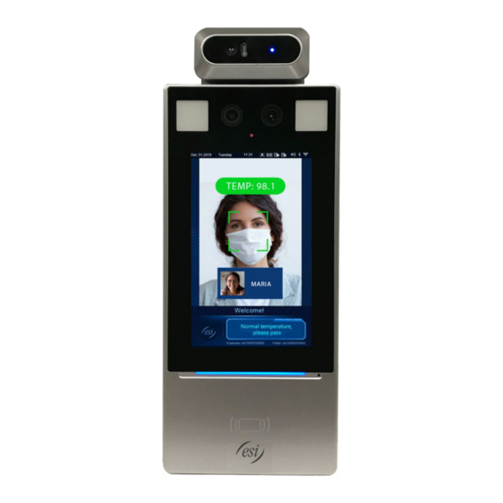
5.4 Mask/Temperature Measurement Interface In response to the current epidemic, companies, parks, and communities take temperatures and check mask wearing for people passing through the entrances and exits. The work is performed by people manually, which is exhausting and increases the risk of cross-infection. The 5D Access Thermal Reader is capable of checking whether people are wearing masks and taking their temperatures. - Page 15 Figure5-5 Normal Temperature and Mask Worn Page 15 of 106 0455-0271 Rev A...
- Page 16 Figure5-6 Mask Worn but Abnormal Temperature NOTE! When both the temperature measurement and mask detection functions are enabled, temperature measurement is prior to mask detection. Once an abnormal temperature is detected, an "abnormal temperature" alarm is reported on the GUI and the warning sound is played no matter whether the person wears a mask or not.
- Page 17 Figure5-7 Normal Temperature but Mask Not Worn 2. Temperature measurement mode The 5D Access Thermal Reader supports pure temperature measurement mode, in which the temperature measurement function is enabled, but no authentication mode is configured in the face library (for details, see “Face Library Management”).
- Page 18 Figure5-8 Temperature Measurement Mode • Normal Temperature: The temperature of a detected person is normal. For the prompt on the GUI and voice prompt, see “Figure 5-5”. Abnormal Temperature: The temperature of a detected person is abnormal. For the prompt on the GUI •...
- Page 19 3. Mask detection The 5D Access Thermal Reader supports mask detection. When a person (whose information is stored in the library) does not wear a mask, an alarm is reported on the GUI and a warning sound is played. For those who do not wear masks, the terminal determines whether to open the door based on actual scenes.
-
Page 20: Activation Config
In the displayed password input interface, enter the configured activation password to go to the “Activation Config” interface. If you forget the password, contact ESI to seek help. NOTE! The initial activation password is configured on the “Initial Interface”. If it is changed (on the “Local Device”... - Page 21 Figure5-11 Activation Password Input Interface On the “Activation Config” interface, you can view basic information about the 5D Access Thermal Reader, configure the device location, network and password and input personnel information and authentication scene. Figure5-12 Activation Config Interface Page 21 of 106 0455-0271 Rev A...
-
Page 22: Basic Info
5.5.1 Basic Info The “Basic Info” interface allows you to view the status of the current device in real time so as to rapidly know about the device condition and better maintain the device. (1) On the “Activation Config” interface, tap to go to the “Basic Info”... - Page 23 Figure5-14 Device Location Interface (2) Configure device location information by referring to the table below. Table5-1 Parameter Description and Configuration Parameter Parameter Description and Configuration Enter the IP address of the management center. After configuration, a user can tap “Call Management Center” on the GUI to call the management center.
-
Page 24: Network Setting
5.5.3 Network Setting On the “Network Setting” interface, you can modify the device IP address and other communication parameters so that the device can communicate with external devices. (1) On the “Activation Config” interface, tap to go to the “Network Setting” interface. Figure5-15 Network Setting Interface (2) Set network parameters by referring to the table below. -
Page 25: User Management
5.5.4 User Management The 5D Access Thermal Reader allows you to input personnel information. Personnel whose information has been input to the device successfully can swipe cards or credentials, or have their faces scanned for access. 1. Face photo collection requirements When adding a person to the whitelist, collect the face photo by strictly observing the following requirements: General requirement: bareheaded full-face photo. - Page 26 Table5-3 Parameter Description and Configuration Parameter Parameter Description and Configuration Remarks Mandatory. Name Enter the name of a person. Enter the gender of the person. Gender Select Male or Female from the drop-down list. The default value is Male. Enter the card No. of the person. Card No.
- Page 27 Figure5-17 Collecting and Inputting a Face Photo On the photo confirmation interface, tap to confirm the collected photo. Is the back button. Figure5-18 Photo Confirmation Interface (4) On the “User Management” interface, tap “Save” to complete the personnel information input. Page 27 of 106 0455-0271 Rev A...
- Page 28 Figure5-19 Save Interface Page 28 of 106 0455-0271 Rev A...
-
Page 29: Activation Password
5.5.5 Activation Password To change the configured activation password, do as follows: (1) On the “Activation Config” interface, tap to go to the “Activation Password” interface. Figure5-20 Activation Password Interface (2) Enter the old password, new password, and confirm the new password as required. NOTE! The password must contain at least eight characters (including at least two of the following ... -
Page 30: Admin Password
5.5.6 Admin Password On the “password-based door opening interface”, users can enter an admin password to open the door. The admin password is applicable to device managerial personnel (such as people in the management center). The admin password is disabled by default. If you need to enable the admin password, tap “Yes” and enter passwords in “Password”... - Page 31 Figure5-22 Authentication Scene Interface Parameter Description and Configuration The 5D Access Thermal Reader only measures people's temperatures and does not conduct another authentication. For the prompt on the GUI, see “Temperature Temperature Measurement Mode”. Measurement Only Note: In this scene, the authentication modes of all libraries configured in the 5D Access Thermal Reader will be cleared.
-
Page 32: Door Opening Method
Mask Detection Enable or disable it based on actual application scenes. Value range: [86–113]°F or [30–45]°C ; default range: [95.9– Temperature 107.6]°F or [34–42]°C Measurement Range in Configure the range based on actual application scenes. Temperature When the digital detection module detects a temperature Configuration higher than the threshold configured here, the "abnormal temperature"... -
Page 33: Card Swiping-Based Door Opening
Figure5-24 Unregistered Person Interface Other face scan-based door opening failures • Some failures may arise during face scan-based door opening. The prompts displayed on the interface are as follows and the effect is similar to the “Unregistered Person” interface. Not a real person. ... -
Page 34: Qr Code-Based Door Opening
5.6.3 QR Code-based Door Opening The 5D Access Thermal Reader supports QR code-based door opening. (1) Tap on the main interface to go to the QR code interface. (2) Aim the generated QR code towards the camera of the 5D Access Thermal Reader or a connected QR code scan device. -
Page 35: Web Operations
6 Web Operations 6.1 Login 6.1.1 Preparation Install the device by referring to the quick reference guide or Installation guide of the product. Connect the device to a power supply and start the device. You can manage and maintain the Visual Intercom 5D Access Thermal Reader in a visualized manner on the Web browser. - Page 36 Figure6-2 Adding the IP Address as a Trusted Site 1.13 NOTE! The IP address 192.168.1.13 in this example is the default IP address. Please replace it with the actual address of your 5D Access Thermal Reader if it has been changed. 3.
-
Page 37: Logging In To The Web Interface
Figure6-3 Setting the Control Permission 6.1.2 Logging In to the Web Interface The default static IP address of the device is 192.168.1.13. The device also supports simple login using the IP address of 192.168.0.13 and subnet mask of 255.255.255.0. The Dynamic Host Configuration Protocol (DHCP) is enabled on the device by default. If a DHCP server is used in the network, the IP address may be assigned dynamically. - Page 38 (3) Enter the username and password, and then click “Login”. Page 38 of 106 0455-0271 Rev A...
- Page 39 Figure6-4 Login Interface The table below describes parameters and plug-ins on the interface and their configuration. Table6-1 Parameter Description and Configuration Parameter/Plug-in Description Configuration Username and password for logging in to the Web interface. At initial login: Enter the username and The default username is admin and the default Username/Password password based...
-
Page 40: Photo
6.2 Photo Face photos captured by the terminal are stored in the “Photo” menu bar. Click “Photo” in the menu bar. The current photo storage status is displayed. Figure6-5 Photo Information Photo List Sorting You can click “Ascending Order” or “Descending Order” to sort the photo list. Total Capacity/Available Capacity The total capacity and available capacity of TMS servers 1 and 2 are displayed. -
Page 41: Refreshing The Photo Library
Figure6-6 Photo Name The naming rule is described as follows: Snapshot time + match result code + highest similarity value (one value) + information about the person corresponding to the highest similarity (person ID + face ID + name) + detected temperature Possible match results include the following: ... -
Page 42: Deleting A Photo
(3) Click “Export” and select the storage path to export the photos. Figure6-7 Export Operation Interface (4) Access the folder that stores the exported photos to view the exported photos. 6.2.5 Deleting a Photo (1) Go to the “Photo List” interface. (2) Select a photo to be deleted. -
Page 43: Exporting And Deleting Photos
6.2.6 Exporting and Deleting Photos When “Export & Delete” is clicked, selected photos will be exported and deleted from the 5D Access Thermal Reader. (1) Go to the “Photo List” interface. (2) Select photos to be exported and deleted. (3) Click “Export & Delete”. (4) In the deletion confirmation box, click “OK”. -
Page 44: Parameter Configuration
6.3 Parameter Configuration 6.3.1 Common Figure6-10 Common Parameter Configuration Interface 1. Basic Info The “Basic Info” interface allows you to view the status of the current device in real time, so as to rapidly know about the device condition and better maintain the device. (1) Choose “Setup >... - Page 45 Figure6-11 Basic Info Interface (2) Click “Refresh” to update the device to the latest state. On the refreshed interface, you can view status information about the current device. 2. Local Settings Set local parameters for your PC. (1) Choose “Setup > Common > Local Settings” to go to the “Local Settings” interface. (2) The figure below shows the “Local Settings”...
- Page 46 Figure6-12 Local Settings Interface Table6-2 Parameter Description and Configuration Area Parameter Description The options are as follows: Disable Enable Intelligent Untriggered Mark Target When this function is enabled, the terminal will track and mark targets. If the face detection function is enabled, the device will track and mark faces.
- Page 47 Type of local recording subsection. The options are as follows: Subsection by Time: Duration of recorded video for each recording Recording file on the computer. For example, 2 minutes. Subsection by Size: Size of each recording file stored on the ...
- Page 48 Figure6-13 Ethernet Configuration Interface (2) Set “Obtain IP Address” as shown in in the figure above. When “Obtain IP Address” is set to “Static”, complete the configuration by referring to the figure • below. Figure6-14 Static Address Configuration Interface Table6-3 Parameter Description and Configuration Parameter Description and Configuration Keep the default value “Off”.
- Page 49 • When “Obtain IP Address” is set to “PPPoE”, complete the configuration by referring to the figure below. If the 5D Access Thermal Reader is connected to the network through Point to Point over Ethernet (PPPoE), you need to select PPPoE as the IP obtainment mode. Figure6-15 PPPoE Configuration Interface Table6-4 Parameter Description and Configuration Parameter...
- Page 50 Table6-6 Parameter Description and Configuration Parameter Description and Configuration The value ranges from 576 to 1500. This parameter is not displayed when “Obtain IP Address” is set to “PPPoE”. Port Type The default value is “FE Port”. Keep the default value. The options are as follows: 10M Half Duplex 10M Full Duplex...
- Page 51 latest time of all servers in the network. Time Zone Select the correct time zone. This parameter is available only when “Sync Mode” is set to “Sync with System Configuration” or “Sync with Latest Server Time”. System Time Configure the correct time. This parameter is available only when “Sync Mode”...
- Page 52 5. Server If the 5D Access Thermal Reader is used in standalone mode, you do not need to configure server information. 6. User The device supports no more than one administrator and a maximum of 32 ordinary users. The administrator is “admin” (the administrator name cannot be modified) by default and has all management and operation permissions for the device and users.
- Page 53 Figure6-20 Ordinary User Information Editing Interface (4) After editing information, click “OK” to save the user information. (3) Deleting an ordinary user (1) Log in to the terminal interface as “admin”. (2) Choose “Setup > Common > User” to go to the “User” interface. (3) Select the ordinary user to be deleted and follow the steps as shown in the figure below to delete the user.
- Page 54 7. Ports & Devices (1) Serial Port When the 5D Access Thermal Reader conducts O&M management on a gate machine through a serial port or it connects to an ID card reader, serial port information needs to be configured. Perform the following operations to configure a serial port: NOTE! The serial port configuration interface varies with the device type.
- Page 55 Table6-9 Parameter Description and Configuration RS485_1 Parameter RS232_1 Security / Temperature Module: Select this option when the 5D Access Thermal Reader connects to a digital thermal IC Card Mode: This option is displayed detection module through the when the 5D Access Thermal Reader has RS485 serial port.
- Page 56 Figure6-23 Wiegand Interface Configuration Window (2) Configure Wiegand interface information by referring to the table below. Table6-10 Parameter Description and Configuration Parameter Configuration Protocol Set it to “Wiegand 26” or “Wiegand 34” based on actual scenes. The options are as follows: •...
- Page 57 Figure6-24 IO Configuration Interface (2) Configure IO port information by referring to the table below. Table6-11 Parameter Description and Configuration Parameter Parameter Description and Configuration F1/F2 indicates the IO port of the 5D Access Thermal Reader. Select the check box in the front. Then, the configuration of the IO port will take effect. IO ports support the following types of external devices: •...
- Page 58 It indicates the interval between two unlock operations. After the door is unlocked, it will not be re-unlocked within the unlock interval even if a new unlock signal is received. In addition, the “door opening duration” of the door lock will not be re-timed. If it is set to 0, door unlock will be triggered each Unlock Interval time the unlock signal is received, and the “door opening duration”...
- Page 59 (1) Choose “Setup > Common > Ports & Devices” and click the “Illumination” tab. (2) Set the LCD light as required. (1.2) Energy Conservation The 5D Access Thermal Reader supports light energy conservation configuration. (1) Choose “Setup > Common > Ports & Devices” and click the “Illumination” tab. (2) Set energy conservation parameters based on actual requirements.
- Page 60 Table6-12 Parameter Description and Configuration Parameter Description Configuration • On: When the 5D Access Thermal Reader detects a face within the preset “Schedule”, all lights (including the LCD light, display screen, and light supplement lamp) are on (only when the brightness of the current ambient light does not reach the minimum brightness threshold of the device).
- Page 61 8. Device Info The “Device Info” interface allows you to configure the current location of the device. (1) Log in to the terminal interface as “admin”. (2) Choose “Setup > Common > Device Info” to go to the “Device Info” interface. Figure6-27 Device Info Configuration Interface Table6-13 Parameter Description and Configuration Parameter...
- Page 62 9. Personalization (1) Ad Mode The 5D Access Thermal Reader supports Ads (pictures only). The configuration is as follows: (1) Choose “Setup > Common > Personalization” and click the “Ad Mode” tab. (2) Set the Ad mode by referring to the table below. Figure6-28 Ad Mode Setting Interface Table6-14 Parameter Configuration Parameter...
- Page 63 The 5D Access Thermal Reader supports custom logos and prompts. The configuration is as follows: (1) Choose “Setup > Common > Personalization” and click the “Custom Logo and Prompt” tab. (2) Set the custom logo and prompt by referring to the table below. Figure6-29 Custom Logo and Prompt Interface Table6-15 Parameter Configuration Parameter...
-
Page 64: Network
Figure6-30 Custom Button Interface In Development (3) Click “Save” to complete the custom button configuration. 6.3.2 Network 1. Network For the Ethernet configuration interface, see Ethernet. 2. UNP The configuration is not supported. 3. DNS The configuration is not supported. 4. -
Page 65: Image
6.3.3 Image 1. Image (1) Scenes Set image parameters to achieve the desired image effects based on live video in different scenes. (1) Click “Setup > Image > Image” and then click “Scenes”. Figure6-31 Scene Configuration Interface (2) Scene Name: name of the current scene. Several scene modes have been preset in the device. After a scene mode is selected, image parameters are automatically switched (you can adjust image parameters as required). - Page 66 (2) Image Enhancement NOTE! All parameters on the “Image Enhancement” interface use default values and cannot be configured. (1) Click “Setup > Image > Image” and then click “Image Enhancement”. Figure6-32 Image Enhancement Interface (2) Use the sliders to change the settings. You may also enter values directly. The following table describes some major parameters.
- Page 67 Table6-16 Parameter Description Item Description Set the degree of brightness of images. Brightness Low brightness High brightness The amount of a hue contained in a color. Saturation Low saturation High saturation Set the degree of difference between the blackest pixel and the whitest pixel. Contrast Low contrast High contrast...
- Page 68 3D Noise Reduce the noise of images. The function may cause motion blur (or ghosting in Reduction some applications). Rotation of the image. Normal Flip Vertical Image Rotation Flip Horizontal 90°Clockwise 90°Anti- clockwise (3) To restore default settings in this area, click “Default”. (3) Exposure (1) Click “Setup >...
- Page 69 Figure6-33 Exposure Configuration Interface (2) Set parameters as required. The table below describes the exposure parameters. Table6-17 Parameter Description and Configuration Item Description Select a mode to achieve the desired exposure effect. Automatic: The device automatically adjusts exposure based on the environment. ...
- Page 70 Control image signals so that the device outputs standard video signals according to the light condition. Gain NOTE! You can set this parameter only when “Exposure Mode” is set to “Manual” or “Gain Priority”. Improves image brightness in low light conditions. NOTE! Slow Shutter You can set this parameter only when “Exposure Mode”...
- Page 71 The value ranges from 0 to 60 and the default value is 5. Page 71 of 106 0455-0271 Rev A...
- Page 72 Automatic: The device outputs the optimum images according to the light condition. In this mode, the device can switch between night mode and day mode automatically. Day/Night Day: The device provides high-quality color images using the existing light. Mode Night: The device provides high-quality black and white images using the existing ...
- Page 73 Figure6-34 Smart Illumination Interface (2) Set smart illumination parameters by referring to the table below based on actual scenes. Item Description Smart Select whether to enable smart illumination based on actual conditions. Illumination Lighting Type It can be set to “White Light” only currently. Manual: After smart illumination is enabled, the light supplement lamp ...
- Page 74 (2) Select a white balance mode as required. The following table describes some major parameters. Item Description Adjust the red or blue offset of the image: Auto/ Auto 2: The device adjusts the red and blue offset automatically according to the light condition (the color tends to be blue).If the images are still unnaturally red or blue in Auto mode, please try Auto2.
- Page 75 2. OSD On Screen Display (OSD) is the text displayed on the screen with video images and may include time and other customized contents. (1) Click “Setup > Image > OSD”. (2) Select the position and content of the OSD. •...
-
Page 76: Intelligent
NOTE! Currently, the OSD configuration is not displayed on the GUI of the 5D Access Thermal Reader. 6.3.4 Intelligent 1. Face Snapshot Face snapshot configuration includes the configuration of face detection, face detection threshold, filter by object size (px), and other parameters. Proper parameter configuration is conducive to face detection and match. - Page 77 Table6-18 Parameter Description and Configuration Pane Parameter Description and Configuration Click Full Screen, indicating that the full-screen face photo will be detected. Detection Area Click “Specified Area”, indicating that face photo of a specified area will be detected. Max.
- Page 78 Figure6-37 Time Template Adding a time template • NOTE! A maximum of 16 time templates can be set. (1) Choose “Setup > Intelligent > Time Template” and click “Add”. (2) Set parameters in the right pane of the interface. “Template Name”: Enter the name of a time template. Requirements: 1–20 characters, with upper- and lower-case English letters, digits, hyphens, and underscores supported.
- Page 79 You can also click to go to the “Edit” interface, on which you can set arming time for a week. A maximum of eight arming time ranges can be set for a day. The time ranges cannot be overlapped. A recognition success prompt is displayed only when the authentication succeeds in the preset arming time ranges.
- Page 80 (2) Click “Delete”. (3) In the displayed confirmation box, click “OK” to delete it. NOTE! If a person is bound to a time template, you need to unbind the person before deleting the time template. Otherwise, a prompt, indicating that deletion failed, and you are required to unbind the person first, is displayed when you delete it.
- Page 81 IC Card+Face: The 5D Access Thermal Reader conducts 1:N match on the acquired card number (IC card number) and the card numbers in the library, and then conducts 1:1 match on the face photo corresponding to the card number and the snapshot photo. An authentication mode is used to configure the method for people to pass through the terminal.
- Page 82 NOTE! A maximum of 16 face libraries can be set. (1) Above the personnel library list, click “Add”. (2) On the displayed “Add Face Library” interface, configure face library information by referring to the table below. Figure6-43 Add Face Library Interface Table6-19 Parameter Configuration Parameter Description and Configuration...
- Page 83 authentication succeeds. The options are as follows: Verify Failure • “Voice Prompt”: A voice prompt is played after the authentication fails. Linkage • “HMI Prompt”: A prompt is displayed on the GUI after the authentication Configuration fails. • Modifying a face library (1) Select a required face library and click “Edit”.
- Page 84 Figure6-45 Add Face Info Interface Table6-20 Parameter Configuration Pane Parameter Description and Configuration It is required. Enter the No. of a person. Requirements: 1–15 characters, with upper- and lower-case English letters, digits, hyphens, and underscores supported. It is required. Name Enter the name of the person.
- Page 85 Effective Time Select a time template and then set the effective time and expiration time of the time template. Expiration Time Select the check box in front of a time template based on the actual situation. NOTE! Time Template • When multiple time templates are bound, the union of the Time Template time templates is taken during authentication.
- Page 86 Figure6-47 Edit Interface (3) On the displayed edit interface, modify person information by referring to “Adding a person”. (4) Click “OK” to complete the modification. Deleting persons • Persons can be deleted one by one or together. Deleting a person (1) Select the check box in the upper left corner of a person to be deleted.
- Page 87 (3) In the displayed deletion confirmation box, click “OK” to complete the deletion. Deleting all persons (1) Select the check box in front of “Select All”. Figure6-49 Selecting All Persons (2) Click (3) In the displayed confirmation box, click “OK” to complete the deletion. Searching for a person •...
- Page 88 Figure6-51 Advanced Setting Interface Page 88 of 106 0455-0271 Rev A...
- Page 89 Table6-21 Parameter Description and Configuration Item Description • Authentication: After “Door Opening Mode” is set to “Authentication”, the terminal generates the door opening signal only after a person passes the authentication in “Check Template”. • Face: After “Door Opening Mode” is set to “Face”, the 5D Access Thermal Reader generates the door opening signal when Door Opening Mode...
- Page 90 • Only Report Small: When access records are reported to the upper-level platform, only small images (that is, fact cutout images) are reported. • Report All: When access records are reported, both large and small images are reported The default value is “Report All”. •...
- Page 91 Measurement Do not need configuration. Terminal will automatically match the temperature measurement mode when it is connected to the digital detection module. The options are “On” and “Off”. Set the parameter based on the actual conditions. Default value is “Off”. After “On”...
- Page 92 detects people who are not wearing a mask. The options are “On” and “Off”. Set the parameter based on the actual conditions. Default value is “Off”. Blacklist Alarm After turning on the blacklist alarm, terminal will output a blacklist alarm when blacklist person is detected.
-
Page 93: Events
Note: This parameter is available only when “Base Image Display” is set to “Single Face”. Single Face: The GUI displays only information about the identified person after face recognition succeeds. Multiple Faces: The GUI displays information about multiple identified persons after ... - Page 94 (2) Set fire alarm information. 1) Select alarm and set the alarm name. 2) Select “N.O. or N.C.” according to the type of the third-party alarm input device. For example, if the third-party alarm input device is normally open, you need to select “N.O.” here, so that the camera can receive alarm information from the third-party alarm input device.
- Page 95 Figure6-54 Tamper Alarm Configuration Interface (2) Set basic information about tamper alarms. 1) Select alarm and set the alarm name. 2) Select the alarm type. Set “Alarm Type to N.O. or N.C.” based on whether the tamper alarm input is of the normally open or normally closed type. 3) Select whether to enable alarm input.
- Page 96 Drawing Arming Time by Using the Editing Tables to Set Arming Time Mouse (5) Click “Save”. Page 96 of 106 0455-0271 Rev A...
- Page 97 3. Door magnet alarms When the 5D Access Thermal Reader connects to a door magnet, it can receive door magnet alarms. (1) Choose “Setup > Events > Events” and then click “Door Magnet Alarm”. Figure6-55 Door Magnet Alarm Configuration Interface (2) Set basic information about door magnet alarms.
-
Page 98: Storage
Drawing Arming Time by Using the Editing Tables to Set Arming Time Mouse (5) Click “Save”. 6.3.6 Storage 1. Storage (1) Click “Setup > Storage > Storage”. NOTE! • Keep default values on the “Storage” interface. Configuration is forbidden. • Formatting is forbidden. 2. -
Page 99: Security
6.3.7 Security 1. User For user configuration, see “User”. 2. Network Security After security information transmission is set, you can establish an information security channel to ensure data transmission security. (1) HTTPS (1) Click “Setup > Security > Network Security > HTTPS”. Figure6-56 HTTPS Setting Interface (2) Select “On”... - Page 100 NOTE! When the 5D Access Thermal Reader is used in combination with indoor monitors, the authentication mode needs to be set to “None”. (3) ARP Protection This function protects a camera from ARP attacks. The gateway and the MAC address must be set properly before a PC can access the camera from another network;...
-
Page 101: System
NOTE! If Filtering Mode is set to Whitelist, then only the added IP address is allowed to access the camera. If Filtering Mode is set to Deny Access, then only the added IP address is not allowed to access the camera. Up to 32 IP addresses are allowed. - Page 102 (2) Device Restart (1) Click “Setup > System > Maintenance”. Figure6-61 Restart Configuration Interface (2) Under “Device Restart”, click “Restart”. The device will restart after you confirm the operation. (3) You can select “Enable Auto Restart” and set the restart time point. Then, the device will automatically restart at the time point.
- Page 103 CAUTION! After you perform the Default operation, all settings are restored to factory defaults, except the following: login password of the system administrator, network settings, and system time. Make sure you import the correct configuration file for your camera. Otherwise, ...
-
Page 104: Live View
7 Live View Live view means playing live video (real-time audio and video) received from a camera in a window through the Web interface. If you log in with the “Live View” check box selected, live video appears by default when you are logged in. - Page 105 Description of the Live View Toolbar Configuration Item Description Play/stop live video. Adjust the output volume for the media player on the PC.(not supported) Adjust the microphone volume on the PC during audio communication between the PC and the camera.(not supported) Take a snapshot of the current image displayed on the PC.
-
Page 106: Faqs
8 FAQs (1) What to do if no message prompts me to install ActiveX when I log in on a Windows 7 PC the first time Answer: Follow these steps to turn off UAC and then log in again: Click the “Start” button, and then click “Control Panel”. In the search box, type uac, and then click “Change User Account Control Settings”.