Table of Contents
Advertisement
TECHNICAL&SERVICE MANUAL
MODEL:
T1 Series
AUF-48ER6SEM1
AUF-60ER6SPM1
AUF-42CR6FEM
AUF-42CR6SEM
T3 SERIES
(COOLING ONLY TYPE,POWER SOURCE:60Hz )
AUF-36CTR2SEM
AUF-48CTR2SPM
AUF-60CTR2SPM
-
AUF 60CTR2SPM1
—Floor Standing Type Air Conditioner
T3Series
(HEAT PUMP TYPE,POWER SOURCE:50Hz)
AUF-36HTR4FAM
AUF-48HTR4FEM
AUF-48HTR6FEM
AUF-60HTR6FPM
AUF-36HTR4FAMA
AUF-48HTR4FEMA
AUF-48HTR6FEMA
AUF-60HTR6FPMA
AUF-48HTR4FEMB
V3.2
Advertisement
Table of Contents

Related Manuals for Hisense T1 Series


Summary of Contents for Hisense T1 Series
- Page 1 TECHNICAL&SERVICE MANUAL V3.2 —Floor Standing Type Air Conditioner MODEL: T1 Series T3Series (HEAT PUMP TYPE,POWER SOURCE:50Hz) AUF-48ER6SEM1 AUF-36HTR4FAM AUF-60ER6SPM1 AUF-48HTR4FEM AUF-42CR6FEM AUF-48HTR6FEM AUF-42CR6SEM AUF-60HTR6FPM AUF-36HTR4FAMA AUF-48HTR4FEMA AUF-48HTR6FEMA AUF-60HTR6FPMA AUF-48HTR4FEMB T3 SERIES (COOLING ONLY TYPE,POWER SOURCE:60Hz ) AUF-36CTR2SEM AUF-48CTR2SPM AUF-60CTR2SPM AUF 60CTR2SPM1...
-
Page 2: Table Of Contents
Floor Standing Type Air Conditioner Technical & Service Manual Table of Contents Page 1.GENERAL 2.SPECIFICATION 3.OUTLINES AND DIMENSIONS 3-1 INDOOR 3-2 OUTDOOR 4. DIAGRAM&DATA 4-1 Refrigerant Flow Diagram 4-2MAX. Refrigerant Pipe Length and Height Difference 4-3 Electric Diagrams 5.ELECTRICAL DATA 5-1 Electric Wiring Diagrams 5-2 Electric Control 5-3 Dip Switch Setting of Outdoor... -
Page 3: 1.General
1.1 Features Features 24-hour Timer ON and OFF This Timer can be set to automatically turn the unit on or off within a 24-hour period. Mute Operation The excellent fan design enable the airflow to be quiet and smooth with minimum noise. Various Refrigerant Pipe Connect Methods The refrigerant pipe can be connected from 3 different directions(rear,right or left) . - Page 4 1.2 Product Lineup Type Model Floor Standing AUF- ● ● ● ● Type FLOOR STANDING AIR CONDITIONER TECHNICAL&SERVICE MANUAL V3.1...
- Page 5 1.3 MODEL IDENTIFICATION A U F -36 H T R 4 F A M M:Indoor Unit Indetification A:Outdoor Unit Indetification S:Refrigerant R410A F:Refrigerant R22 2:220V-240V/60HZ/1P 4:220V-240V/50HZ/1P 6:380V-415V/50HZ/3P X: Wire Romote Controller R:Wireless Romote Controller T:T3 Climate Type U:DC-Invert Heat Pump Type H:Heat Pump Type C:Cooling Only Cool Capacity:36x10 Btu/h Type:D-Duct Type,C-Cassette Type,F-Floor StandingType,W-Outdoor Unit Unit...
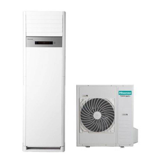
- Page 6 1.4 Product Picture Indoor Unit FLOOR STANDING AIR CONDITIONER TECHNICAL&SERVICE MANUAL V3.1...
- Page 7 Outdoor Unit MODEL(Kbtu/h) 36K(except AUF-36CTR2SEM) 48K,42K& 36K(AUF-36CTR2SEM) View MODEL(KBtu/h) 48K(AUF-48CTR2SPM),60K View FLOOR STANDING AIR CONDITIONER TECHNICAL&SERVICE MANUAL V3.1...
- Page 8 FLOOR STANDING AIR CONDITIONER TECHNICAL&SERVICE MANUAL V3.1...
- Page 9 DISPLAY PANEL FLOOR STANDING AIR CONDITIONER TECHNICAL&SERVICE MANUAL V3.1...
- Page 10 FLOOR STANDING AIR CONDITIONER TECHNICAL&SERVICE MANUAL V3.1...
-
Page 11: 2.Specification
2. Specifications Floor Standing Type Climate:T3 Model AUF-36HTR4FAM AUF-48HTR4FEM AUF-60CTR2SPM Indoor model AUF-36HR4FM AUF-48HR4FM AUF-60CR2SM Outdoor model AUW-36HT4FA1 AUW-48HT4FE AUW-60CT2SP Power supply Ph-V-Hz 1N,220V-240V/50Hz 1N,220V-240V/60Hz 10/9 14/13 14.2/12.5 Cooling(T1/T3) Btu/h 34100/30700 23900/44400 48500/42700 Capacity 15.5 Heating Btu/h 37,500 52,900 Dehumidification Rated Cooling(T1/T3) 3.55/4.285... - Page 12 Model AUF-36HTR4FAM AUF-48HTR4FEM AUF-60CTR2SPM Indoor model AUF-36HR4FM AUF-48HR4FM AUF-60CR2SM Outdoor model AUW-36HT4FA1 AUW-48HT4FE AUW-60CT2SP circulatio Outdoor Hi/Med/Low m³/h 6000 Static Pressure(*Default Setting) Wireless Remote Operating control Wireless Remote control-J1-05(E) control-J1-05(E) Dimensio Indoor L×W×H 580×380×1870 580×380×1870 580×380×1870 Outdoor L×W×H 950×340×840 950×340×1050 950×340×1386 Indoor L×W×H...
- Page 13 Model AUF-48HTR6FEM AUF-60HTR6FPM AUF-36CTR2SEM Indoor model AUF-48HR4F1M AUF-60HR4FM AUF-36CR2SM Outdoor model AUW-48HT6FE AUW-60HT6FP AUW-36CT2SE Power supply Ph-V-Hz 3N,380V-415V/50Hz 1N,220V-230V/60Hz Cooling(T1/T3) 14000/12500 17500/14000 9200/8000 Capacity Heating 15000 19000 Dehumidification 2.69 Cooling(T1/T3) 4360/5000 5450/6600 2628/3112 Rated input Heating 4150 5260 Rated Cooling(T1/T3) 7.3/8 9/11...
- Page 14 Model AUF-48HTR6FEM AUF-60HTR6FPM AUF-36CTR2SEM Indoor model AUF-48HR4F1M AUF-60HR4FM AUF-36CR2SM Outdoor model AUW-48HT6FE AUW-60HT6FP AUW-36CT2SE Max. difference in level 20/15 Connection method Flare Connection Power wiring 5 core x2.5 5 core x2.5 3 core x2.5 wiring Signal wiring 4core x0.75 4core x0.75 4core x0.75 Refrigerant type R410A...
- Page 15 Model AUF-36HTR4FAMA AUF-48HTR4FEMA AUF-48HTR4FEMB Indoor model AUF-36HR4FMA AUF-48HR4FMA AUF-48HR4FMB Outdoor model AUW-36HT4FA1 AUW-48HT4FE AUW-48HT4FE Power supply Ph-V-Hz 1N,220V-240V/50Hz Cooling(T1/T3) 10/9 14/13 14/13 Capacity Heating 15.5 15.5 Dehumidification Cooling(T1/T3) 3.55/4.285 4.982/6.5 4.982/6.5 Rated input Heating 3.225 5.516 5.516 Rated Cooling(T1/T3) 15.8/19 24/31 24/31 Current...
- Page 16 Model AUF-36HTR4FAMA AUF-48HTR4FEMA AUF-48HTR4FEMB Indoor model AUF-36HR4FMA AUF-48HR4FMA AUF-48HR4FMB Outdoor model AUW-36HT4FA1 AUW-48HT4FE AUW-48HT4FE Max. difference in level Connection method Flare Connection Power wiring 3 core x2.5 3 core x6.0 3 core x6.0 wiring Signal wiring 4core x0.75 4core x0.75 4core x0.75 Refrigerant type Refrigerant charge...
- Page 17 Model AUF-48HTR6FEMA AUF-60HTR6FPMA Indoor model AUF-48HR4F1MA AUF-60HR4FMA Outdoor model AUW-48HT6FE AUW-60HT6FP Power supply Ph-V-Hz 3N,380V-415V/50Hz Cooling(T1/T3) 14000/12500 17500/14000 Capacity Heating 15000 19000 Dehumidification Cooling(T1/T3) 4360/5000 5450/6600 Rated input Heating 4150 5260 Rated Cooling(T1/T3) 7.3/8 9/11 Current Heating Max. input 6300 9000 Max.current...
- Page 18 Model AUF-48HTR6FEMA AUF-60HTR6FPMA Indoor model AUF-48HR4F1MA AUF-60HR4FMA Outdoor model AUW-48HT6FE AUW-60HT6FP Connection method Flare Connection Power wiring 5 core x2.5 5 core x2.5 wiring Signal wiring 4core x0.75 4core x0.75 Refrigerant type Refrigerant charge Throttle Type Capillary Capillary Cooling15~52 Ambient temp. ℃...
- Page 19 Model AUF-48CTR2SPM AUF-60CTR2SPM1 Indoor model AUF-48CR2SM AUF-60CR2SM1 Outdoor model AUW-48CT2SP AUW-60CT2SP1 Power supply Ph-V-Hz 1N,220V-230V/60Hz Cooling(T1/T3) 13600/11900 14650/12600 Capacity Heating Dehumidification 5.48 6.12 Cooling(T1/T3) 3880/4740 4220/5020 Rated input Heating Rated Cooling(T1/T3) 17.6/21.5 18.7/22.4 Current Heating Max. input 5900 6270 Max.current 27.4 32.5...
- Page 20 Model AUF-48CTR2SPM AUF-60CTR2SPM1 Indoor model AUF-48CR2SM AUF-60CR2SM1 Outdoor model AUW-48CT2SP AUW-60CT2SP1 Max. difference in level Connection method Flare Connection Power wiring 3 core x6.0 3 core x6.0 wiring Signal wiring 4core x1.5 4core x1.5 Refrigerant type R410A R410A Refrigerant charge 3.45 3.55 Throttle Type...
- Page 21 Climate:T1 Model AUF-42CR6FEM AUF-48ER6SEM1 AUF-60ER6SPM1 Indoor model AUF-42CR4FM AUF-48ER6SM AUF-60ER6SM Outdoor model AUW-42C6FE AUW-48H6SE1 AUW-60H6SP1 3Ph,380V-415V/5 Power supply Ph-V-Hz 3Ph,380V-415V/50Hz 3Ph,380V-415V/50Hz 12.5 Cooling Capacit Btu/h 42,700 47,770 54590 15+3.6 17+3.6 Heating Btu/h 51180+12280 58000+12280 Dehumidification 5.44 6.76 Rated Cooling 4.25 4.65 5.31 input...
- Page 22 Model AUF-42CR6FEM AUF-48ER6SEM1 AUF-60ER6SPM1 Indoor model AUF-42CR4FM AUF-48ER6SM AUF-60ER6SM Outdoor model AUW-42C6FE AUW-48H6SE1 AUW-60H6SP1 Dimensi Indoor L×W×H 580×380×1870 580×380×1870 580×380×1870 Outdoor L×W×H 950×340×1050 950×340×1050 950×340×1386 Indoor L×W×H 2000×690×480 2000×690×480 2000×690×480 Packing Outdoor L×W×H 1110×460×1200 1110×460×1200 1110×460×1530 Indoor Net/Gross 48/60 55/60 55/60 Weight Outdoor...
- Page 23 AUF-42CR6SEM Model AUF-42CR4SM Indoor Unit Panel Pic. Outdoor Unit AUW-42C6SE Type T1,Cooling Only Ratings T1 Cooling Capacity 13000 Heating Capacity —— T1 Rated 4420 Input-Cooling Rated Input-Heating —— Moisture Removal L/H.r Air Circulation CMH Max 2000 T1 EER for Cooling 2.94 COP for Heating ——...
- Page 24 Display on Front Panel LCD Wireless Remote Controller Removable and washable Panel Washable PP Filter 24 Hours Timer 4 Speed and Auto Indoor Fan Control Vertical Auto Swing Louver Horizontal Auto Swing Louver Dimmer Sleep Operation Smart Function Super Function Auto Restart Other Net Dimensions...
-
Page 25: 3.Outlines And Dimensions
3. OUTLINES AND DIMENSIONS 31 INDOOR (UNIT:mm) FLOOR STANDING AIR CONDITIONER TECHNICAL& SERVICE MANUAL V3.2... -
Page 26: Outdoor
3-2.OUTDOOR (UNIT: mm) (except AUF-36CTR2SEM) FLOOR STANDING AIR CONDITIONER TECHNICAL& SERVICE MANUAL V3.2... - Page 27 42K,48K (except AUF-48CTR2SPM ) &36K (AUF-36CTR2SEM) FLOOR STANDING AIR CONDITIONER TECHNICAL& SERVICE MANUAL V3.2...
- Page 28 48K(AUF-48CTR2SPM)&60K FLOOR STANDING AIR CONDITIONER TECHNICAL& SERVICE MANUAL V3.2...
-
Page 29: 4. Diagram&Data
& & 4. Diagrams DATA & 4.1 Piping Diagrams T3 Type 36K(except AUF‐36CTR2SEM) AUF‐36CTR2SEM FLOOR STANDING AIR CONDITIONER TECHNICAL&SERVICE MANUAL V3.2... - Page 30 & & 48k&60K HEAT PUMP TYPE 48K&60K COOLING ONLY TYPE FLOOR STANDING AIR CONDITIONER TECHNICAL&SERVICE MANUAL V3.2...
- Page 31 & & T1 Type: 48K/60K 42K FLOOR STANDING AIR CONDITIONER TECHNICAL&SERVICE MANUAL V3.2...
-
Page 32: 4-2Max. Refrigerant Pipe Length And Height Difference
& & 4.2MAX. Refrigerant pipe length and height difference Model(Kbtu/h) 42K,48K,60K Max. refrigerant pipe length Max. difference in level *Do your best to reduce the pipe length. Long pipe may cause capacity of the indoor unit incline. The refrigerant charge volume for the unit is based on using a 5m connecting pipe. If the connecting pipe's length is longer than 5m, it is advisable to charge additional Refrigerant for the unit in order to achieve better operation. Additional Refrigerant= (L-5)×0.035kg (* "L" refers to length of connection pipe.) ... -
Page 33: Electric Diagrams
& & 4.3ELECTRIC Diagrams FLOOR STANDING AIR CONDITIONER TECHNICAL&SERVICE MANUAL V3.2... - Page 34 & & Recommended Wire Size Power Source Cable Size Transmitting Cable Size Series Model POWER SUPPLY (mm2) (mm2) 3Ph,380V-415V/50Hz 5×2.5 4×0.75 three phase 4core×0.75(transmitting cable) voltage 48K/60K 3Ph,380V-415V/50Hz 5core×2.5 4core×1.5(electrical heater Series connecting cable) single 220-240V ~,50Hz 3×2.5 4×0.75 phase 220-240V ~,50Hz 3×6.0 4×0.75...
- Page 35 & & 4) In the case that power cables are connected in series, add each unit maximum current and select wires below. * in the case that current exceeds 63A, do not connect cables in series. FLOOR STANDING AIR CONDITIONER TECHNICAL&SERVICE MANUAL V3.2...
-
Page 36: 5.Electrical Data
5-1.Electrical wiring diagrams INDOOR UNIT: AUF-36HTR4FAM, AUF-48HTR4FEM, AUF-42CR6FEM, AUF-42CR6SEM, AUF-60CTR2SPM FLOOR STANDING AIR CONDITIONER TECHNICAL&SERVICE MANUAL V3.1... - Page 37 AUF-48ER6SEM1 AUF-60ER6SPM1 FLOOR STANDING AIR CONDITIONER TECHNICAL&SERVICE MANUAL V3.1...
- Page 38 AUF-36CTR2SEM AUF-48CTR2SPM AUF-60CTR2SPM1 Electric wiring diagram 1838641. A Coil temperature sensor VDC (6) GND (4) COIL VCC (3) Vsp (2) FB (1) ROOM Room temperature sensor DC motor X801 DC FAN SWING YEL/GRN SWING MOTOR CN23 STEP STEP Main control board CN15 OUTSIDE INPUT OUT INPUT...
- Page 39 OUTDOOR UNIT: 36K(AUF-36HTR4FAM) FLOOR STANDING AIR CONDITIONER TECHNICAL&SERVICE MANUAL V3.1...
- Page 40 48K(AUF-48HTR4FEM) FLOOR STANDING AIR CONDITIONER TECHNICAL&SERVICE MANUAL V3.1...
- Page 41 42K(AUF-42CR6FEM, AUF-42CR6SEM) FLOOR STANDING AIR CONDITIONER TECHNICAL&SERVICE MANUAL V3.1...
- Page 42 36K(AUF-36CTR2SEM) 48K(AUF-48CTR2SPM) 60K(AUF-60CTR2SPM) FLOOR STANDING AIR CONDITIONER TECHNICAL&SERVICE MANUAL V3.1...
- Page 43 AUF-48ER6SEM1 48K( FLOOR STANDING AIR CONDITIONER TECHNICAL&SERVICE MANUAL V3.1...
- Page 44 AUF-60ER6SPM1) 60K( FLOOR STANDING AIR CONDITIONER TECHNICAL&SERVICE MANUAL V3.1...
- Page 45 AUF-60CTR2SPM1) 60K( Electric wiring diagram 1850836.B DC FAN MOTOR YEL/GRN CN25 CN 801 Terminal panel FAN - UP TO INDOOR 1(L) CN802 Uin(CN26) FAN - DOWN Nin(CN17) 2(N) SI(CN11) YEL/GRN Terminal panel CN401 Win(CN23) CN402 Main control board Vin(CN22) CN403 CN404 AC 220 V YEL/GRN...
-
Page 46: Electric Control
5-2. CONTROL BOARD INDOOR UNIT(AC MOTOR) INDOOR UNIT(DC MOTOR) AUF-36CTR2SEM、AUF-48CTR2SPM&AUF-60CTR2SPM1 FLOOR STANDING AIR CONDITIONER TECHNICAL&SERVICE MANUAL V3.1... - Page 47 OUTDOOR UNIT (AC MOTOR) OUTDOOR UNIT (DC MOTOR) ① Control Board AUF-60CTR2SPM1 FLOOR STANDING AIR CONDITIONER TECHNICAL&SERVICE MANUAL V3.1...
-
Page 48: Dip Switch Setting Of Outdoor
Power Board ② AUF-60CTR2SPM1 5-3. Dip Switch Setting FLOOR STANDING AIR CONDITIONER TECHNICAL&SERVICE MANUAL V3.1... -
Page 49: Other Settings
System Parameter Adjustment Internal control parameter adjustment can be performed using wire remote controller YXE-C01U/YXE-C02U. OPERATION: ①Hold down both“MODE”button and“ADD.FUNC.”button for 3 seconds, symbol and parameter number blinking at the same time. ”“ ”button to adjust parameter number until display “17”. ②Press“... - Page 50 PARAMETER VALUE&REPRESENTATION PARAMETER PARAMETER NOTE DATA CODE DESCRIPTION REPRESENTATION(FUNCTION CODE) TYPE Heating Temperature -0.5 -1.5 : ℃; : ℃; : ℃; : ℃; Compensation ( indoor : ℃; : -2.5 ℃; : ℃; : -3.5 ℃; Integer unit temperature -4.5 the wired :...
-
Page 51: Sensor Parameter
5-5. Sensor parameter 1. THE PARAMETER OF OUTDOOR COMPRESSOR DISCHARGE TEMPERATURE SENSOR: (R =187.25K±6.3%;R =3.77K±2.5K;B0/100=3979K±1%) T [ ℃ ] Rmin [ KΩ ] Rnom [ KΩ ] Rmax [ KΩ ] DR(MIN)% DR(MAX)% 7.47 908.2603 985.5274 1065.1210 -7.84 7.42 855.3955 927.6043 1001.9150 -7.78... - Page 52 T [ ℃ ] Rmin [ KΩ ] Rnom [ KΩ ] Rmax [ KΩ ] DR(MIN)% DR(MAX)% 5.50 107.8202 114.4973 121.1586 -5.83 5.46 102.8560 109.1728 115.4734 -5.79 5.41 98.1470 104.1246 110.0855 -5.74 5.37 93.6787 99.3367 104.9778 -5.70 5.33 89.4378 94.7946 100.1342 -5.65...
- Page 53 T [ ℃ ] Rmin [ KΩ ] Rnom [ KΩ ] Rmax [ KΩ ] DR(MIN)% DR(MAX)% 3.87 17.6458 18.3926 19.1338 -4.06 3.84 16.9986 17.7113 18.4185 -4.02 3.83 16.3784 17.0537 17.7335 -3.96 3.77 15.7839 16.4332 17.0774 -3.95 3.74 15.2139 15.8338 16.4488 -3.92...
- Page 54 T [ ℃ ] Rmin [ KΩ ] Rnom [ KΩ ] Rmax [ KΩ ] DR(MIN)% DR(MAX)% 2.55 4.1453 4.2568 4.3683 -2.62 2.52 4.0218 4.1287 4.2355 -2.59 2.50 3.9024 4.0049 4.1074 -2.56 2.47 3.7872 3.8854 3.9837 -2.53 2.44 3.6758 3.7700 3.8643 -2.50...
- Page 55 2. THE PARAMETER OF THE OTHER SENSOR IN INDOOR AND OUTDOOR UNIT: ( R =15K±2%; B0/100=3450K±2%) T [℃] Rmin [ KΩ ] Rnom [ KΩ ] Rmax [ KΩ ] DR(MIN)% DR(MAX)% 6.12 60.78 64.77 68.99 -6.16 5.83 57.75 61.36 65.16 -5.88 5.57...
- Page 56 T [℃] Rmin [ KΩ ] Rnom [ KΩ ] Rmax [ KΩ ] DR(MIN)% DR(MAX)% 2.33 9.199 9.422 9.647 -2.37 2.40 8.826 9.047 9.269 -2.44 2.48 8.470 8.689 8.910 -2.52 2.57 8.129 8.347 8.567 -2.61 2.66 7.804 8.021 8.240 -2.71 2.76 7.493...
- Page 57 T [℃] Rmin [ KΩ ] Rnom [ KΩ ] Rmax [ KΩ ] DR(MIN)% DR(MAX)% 5.82 1.888 2.005 2.129 -5.84 5.87 1.827 1.941 2.062 -5.87 5.91 1.767 1.880 1.998 -6.01 5.99 1.710 1.820 1.936 -6.04 6.02 1.655 1.763 1.876 -6.13 6.11 1.602...
- Page 58 T [℃] Rmin [ KΩ ] Rnom [ KΩ ] Rmax [ KΩ ] DR(MIN)% DR(MAX)% 8.23 0.5064 0.5519 0.6014 -8.24 8.27 0.4923 0.5369 0.5853 -8.31 8.32 0.4787 0.5224 0.5698 -8.37 8.36 0.4655 0.5083 0.5547 -8.42 8.42 0.4528 0.4946 0.5401 -8.45 8.46 0.4404...
-
Page 59: 6.Control Mode
6-1 Indoor control mode 1.Major general technical parameters 1 Remote receiver distance: 8 m. 2 Remote receiver angle: Less than 80 degrees. 3 Temperature control accuracy: ±1℃. 4 Time error: Less than 1%. 2. Functions of the controller Control function 2.1 Emergency switch Press the emergency button can realize the starting or closing Machine, starting up according to the automatic mode of operation(invalid for duct type air-conditioner)... - Page 60 will start in the timer off condition. When the set time is up, the air conditioner will turn off after receiving a signal from the remote controller. If the air conditioner has not received a signal from the remote controller when the set time is up, it will turn off automatically. 3.
- Page 61 The heating mode, remote shutdown, such as indoor heat exchanger temperature is higher, the wind blowing out opportunities continue to run the waste heat. Cool and dehumidification mode , after the compressor close, indoor machine will continue to set the speed of operation for a period of time. 2.9 automatically model This model does not automatically model function, emergency button cannot set the automatic mode of operation, can use the emergency switch shutdown, remote setting the...
-
Page 62: Outdoor Control Mode
6-2 Outdoor mode control Control function 1.Cooling Anti-freeze Protection To prevent indoor air conditioner evaporator temperature is too low, the indoor coil sensor for real time detection of evaporator. If the indoor coil temperature is too low, the compressor will protect. 2. - Page 63 To prevent compressor from restart frequently in the condition that system pressure has not been completely balanced, it can’t be restarted within 3 minutes. 7. Pressure Protection: When the pressure increases to a preset value, the pressure switch will automatically protect. Compressor will stop and report the fault code protection. FLOOR STANDING AIR CONDITIONER TECHNICAL&...
-
Page 64: 7.Trouble Shooting
7-1- Error code Trouble guide When the air conditioner failure occurs, the fault code will displays on control board , wire remote controller or display panel. HOW TO CHECK FAULT CODES INDOOR UNIT 1.WALL MOUNTED TYPE For Free-match series Run the air-conditioner by wireless remote controller , continue pressing “SLEEP ”button for 4 times, fault codes will flashing rapidly on the... - Page 65 MOEDL:YXE-C01U FIG.2 ERROR CODE DISPLAY ON WIRE REMOT CONTROLLER (2)CHECK ERROR CODES BY DISPLAY PANEL(CASSETTE type and CEILING &FLOOR type) Display by lamp indicator Lamp RUN(LED2 ,red) and Lamp DEFROST(LED5 ,green)flashing,Lamp RUN display fault code ten digit number, lamp DEFROST display fault code single digit number (as shown fig. below). For example,fault code 36:...
- Page 66 FLOOR STANDING AIR CONDITIONER SERVICE MANUAL V3.2...
- Page 67 LED FALSH CONTROL:flash 300mS(T1),off 300mS(T2),after 2000mS(T3)fault code repeat displays. (as shown below) T1 T2 Fig.2 LED FALSH CONTROL 3.Duct type indoor units of VRF---FAULT CODE DISPLAY BY INDOOR BOARD LED2 and LED5 are failure indicate lamps, LED2(YELLOW) indicate fault code ten digit number, LED5(GREEN) indicate single digit number code FLOOR STANDING AIR CONDITIONER SERVICE MANUAL V3.2...
- Page 68 2.OUTDOOR UNIT FAULT CODE DISPLAY (1) ON/OFF UNITARY TYPE(with outdoor control box) Fault code display by indicate lamps of outdoor control board flash. The times that the lamp flashes equal to fault code. LED2-fault code lamp LED FALSH CONTROL: flash 300mS(T1), off 300mS(T2), after 900mS(T3)fault code repeat displays. (as shown below) T1 T2 (2)INVERTER UNITARY AIR CONDITONER , MULTI-SPLIT TYPE AIR CONDITONER&VRF:...
- Page 69 Outdoor Control Board Digital Tube FOR INVERTER UNITARY AIR CONDITONER&VRF * VRF: Indoor unit can indicate both indoor failure and outdoor failure ,but outdoor only indicate outdoor’s. FOR MULTI-SPLIT TYPE Error code display on digital tube board directly. FLOOR STANDING AIR CONDITIONER SERVICE MANUAL V3.2...
- Page 70 3.Fault code display ( Driver Board ) The lamp of driver board flash shows failure occur. Or, fault code can be check on digital tube board . FLOOR STANDING AIR CONDITIONER SERVICE MANUAL V3.2...
- Page 71 The following is the fault code table of outdoor. sheet 1 Outdoor Error Code Fault Fault Description Possible Reason of Abnormality How to Deal With REMARKS code 1.Reconnect the outdoor ambient 1.The outdoor ambient temperature sensor temperature sensor; connect loose; Outdoor ambient temperature 2.Replace the outdoor ambient 2.The outdoor ambient temperature sensor is...
- Page 72 Fault Fault Description Possible Reason of Abnormality How to Deal With REMARKS code Applied to 1.Replace outdoor ambient ON/OFF 1.Outdoor ambient temperature sensor fault; temperature sensor; air-condition Motor blockage protection 2. Outdoor coil temperature sensor fault; 2.Replace outdoor coil temperature ers with 2 3.Outdoor control board fault.
- Page 73 Fault Fault Description Possible Reason of Abnormality How to Deal With REMARKS code 3.Replace the outdoor control board supply models Application 1. Normally protection 1.Three-phase power is abnormal; 2. Check the wiring connection refer to three-phase voltage absent phase 2.The outdoor wiring connect wrong; the wiring diagram;...
- Page 74 Fault Fault Description Possible Reason of Abnormality How to Deal With REMARKS code 1.Reconnect the wiring of the suction 1.The wiring of the suction temperature temperature sensor; Suction temperature sensor sensor connect loose; 2.Replace the suction temperature fault 2. The suction temperature sensor is failure; sensor;...
- Page 75 Fault Fault Description Possible Reason of Abnormality How to Deal With REMARKS code 2.The sensor of the expansion valve A(thick 2. Replace the sensor for the &inverter tube)is failure; expansion valve A(thick tube); unitary types 3.The sampling circuit is abnormally 3.
- Page 76 Fault Fault Description Possible Reason of Abnormality How to Deal With REMARKS code 2.The high-pressure pressure sensor is 2.Replace the high-pressure pressure failure sensor; 3.The sampling circuit of the high-pressure 3.Replace the outdoor control board. pressure sensor is failure 1.The wiring of the low-pressure pressure 1.Reconnect the wiring of the sensor connect loose;...
- Page 77 Fault Fault Description Possible Reason of Abnormality How to Deal With REMARKS code as capillary, expansion valve) 4. Normally protection. 1.Reconnect the wiring of the up DC 1.The wiring of the up DC fan motor connect fan motor; loose; 2.Replace the up DC fan motor; 2.
- Page 78 Fault Fault Description Possible Reason of Abnormality How to Deal With REMARKS code 1. The wiring of the sensor connect loose; 1. Reconnect the wiring of the sensor; Expansion valve E 2.The sensor of the expansion valve Eis 2. Replace the sensor for the FOR Branch temperature sensor fault failure;...
- Page 79 Fault Fault Description Possible Reason of Abnormality How to Deal With REMARKS code the refrigerant of the unit is not Discharge the refrigerant and charge The refrigerant of the unit is not enough enough fault the refrigerant refer to the rating label 1.The wiring of the 4-way valve coil connect 1.
- Page 80 The following is the fault code table of indoor. Sheet 2 Indoor Error Code List Fault Fault Description Possible Reason of Abnormality How to Deal With REMARKS code 1. The buttons are failure; 1. Replace the display board; 2. The cable of the display board is 2.
- Page 81 Fault Fault Description Possible Reason of Abnormality How to Deal With REMARKS code 1. The connection cable between the indoor unit and the outdoor unit connect 1. Reconnect the connection cable wrong; refer to the indoor and outdoor 2.The communication cable between wiring diagram;...
- Page 82 Fault Fault Description Possible Reason of Abnormality How to Deal With REMARKS code 1. Check whether there are something to block the drain hose or the height of the drain hose is too 1. The water level of the drain pan high;...
- Page 83 Fault Fault Description Possible Reason of Abnormality How to Deal With REMARKS code 4.Indoor control board is failure. 1. The cable of the water tank water temperature sensor 2 connect loose; 1. Reconnect the cable of the water 2. The cable of the water tank water temperature sensor 2;...
- Page 84 Fault Fault Description Possible Reason of Abnormality How to Deal With REMARKS code indoor unit and the outdoor unit is wiring diagram; failure or 4. Replace the indoor control board; the cable between the indoor control 5. Replace the outdoor control board. board to terminal is failure or the cable between...
- Page 85 Fault Fault Description Possible Reason of Abnormality How to Deal With REMARKS code 1. The cable of the room temperature 1.Reconnect the cable of the room sensor connect loose; temperature sensor; Indoor ambient 2. The room temperature sensor is 2. Replace the room temperature Temperature Sensor Fault failure;...
- Page 86 Fault Fault Description Possible Reason of Abnormality How to Deal With REMARKS code 1. The cable of the temperature sensor 1. Reconnect the able of the temperature sensor of the outlet of The outlet of water the outlet of water side is failure; water side;...
- Page 87 Fault Fault Description Possible Reason of Abnormality How to Deal With REMARKS code 1.The wiring between the display board to 1. Reconnect the between the display the indoor control board connect loose; board to the indoor control board; 2.The sequence of the wiring between 2.
- Page 88 The expansion valve or the capillary is failure Replace the expansion valve or the capillary Note 4:Over load in heating mode Overload in heating mode The root cause Corrective measure Discharge the refrigerant, and recharge the refrigerant refer to the The refrigerant is excessive rating label The indoor ambient temperature is too high...
- Page 89 The following is the fault code table of driver board. Analysis of the Driving Board Fault (Except Free-match 20K&16K DUAL TYPES), Driver board fault codes trouble shooting details see sheet 5. I. Driver fault code display by indicate lamps of driver board flashing. The times that the lamp flashes equal to fault code.
- Page 90 Fault Fault Description Possible Reason of Abnormality How to Deal With code 3, Compressor oil shortage,serious wear of 3, Change the Compressor; crankshaft; 4, Change the Compressor. 4,The compressor insulation fault. Communication between 1,Communication wire connect not well; 1, Check compressor wire connect. driver board and control 2,Driver board fault;...
- Page 91 (ONLY FOR 20K&16K DUAL TYPES), Ii: Driver board fault codes trouble shooting details see sheet6. 2-seconds long LED flash on/off in means number 5,1 -second short LED flash on/off means number 1. 1 time flash 1 time flash LED ON LED ON LED OFF LED OFF...
- Page 92 Fault Fault Description Possible Reason of Abnormality How to Deal With code failure ; 3、Change the driver 3、Driver board failure. board. 1、 System overload, current too 1、Check the system; PFC overload current detection of high; 2、Change the driver failure. 2、 Driver board failure; board;...
-
Page 93: 8.Checking Components
8-1. Check refrigerant system TEST SYSTEM FLOW Conditions: ① Compressor is running. ② The air condition should be installed in good ventilation. Tool: Pressure Gauge Technique: ① see ② feel ③ test ----- Tube defrost. FEEL ----- The difference between tube’s temperature. TEST ----- Test pressure. - Page 94 Test system flow Cooling mode Test system The pressure on the pressure.Does the low high side. pressure normal at service part ? Recharge refrigerant after air purging with If the pressure is The pressure on the the vacuum close to static low side.
-
Page 95: Check Parts Unit
8-2.Check parts unit 1. INDOOR FAN MOTOR T1 Series: 42K,48K,60K MODEL: Y7S059D801 T3 Series: 36K(AUF-36HTR4FAM, AUF-36HTR4FAMA) MODEL:Y7S059D501 FLOOR STANDING AIR CONDITIONER SERVICE MANUAL V3.2... - Page 96 36K(AUF-36CTR2SEM) 48K(AUF-48CTR2SPM) 60K(AUF-60CTR2SPM1) MODEL:EQDW07AQH DC MOTOR 48K(AUF-48HTR4FEM, AUF-48HTR4FEMA, AUF-48HTR4FEMB) MODEL:Y7S862D820 48K(AUF-48HTR6FEM, AUF-48HTR6FEMA) MODEL:Y7S862D801 60K(AUF-60CTR2SPM) MODEL:Y7S059E001 FLOOR STANDING AIR CONDITIONER SERVICE MANUAL V3.2...
- Page 97 3) Please don’t drop hurl or dump motor against hard material. Malfunction may not be observed at early stage after such shock. But it may be found later, this type of mishandling void our warranty. 2. OUTDOOR FAN MOTOR T1 Series: 36K,42K MODEL:YDK29-6I-39 M:BLACK-BLUE 187±15%...
- Page 98 Model: YDK65-6-9024,YDK65-6-9061 T3 Series: 36K(AUF-36HTR4FAM, AUF-36HTR4FAMA) MODEL:YDK95-6-9063A BLACK-WHITE: 67±12% BLACK-BLUE:23.6±12% BLUE-RED:17.7±12% BLACK-YELLOW:79.9±12% FLOOR STANDING AIR CONDITIONER SERVICE MANUAL V3.2...
- Page 99 36K(AUF-36CTR2SEM) MODEL:YDK69-6I-42, YDK69-6I-40 M: WHITE-RED 273±15% A:BROWN-BLACK 100±15% 48K(AUF-48HTR4FEM, AUF-48HTR4FEMA, AUF-48HTR4FEMB) MODEL:YDK29-6I-36 ,YDK29-6I-37 M:228±15% A:150±15% 48K(AUF-48HTR6FEM, AUF-48HTR6FEMA) MODEL: YDK29-6I-39 MODEL:YDK29-6I-39 M:BLACK-BLUE 187±15% A:BLUE-RED-WHITE-YELLOW:50/21/106±15% MODEL:YDK29-6I-41 M:BLACK-BLUE 187±15% A:BLUE-RED-WHITE-YELLOW:50/21/106±15% FLOOR STANDING AIR CONDITIONER SERVICE MANUAL V3.2...
- Page 100 48(AUF-48CTR2SPM) 60K(AUF-60CTR2SPM) MODEL: YYW95-8-8523 YYW95-8-8526 BLACK-WHITE: 64±12% BLACK-BLUE:24±12% BLUE-RED:14±15% BLACK-YELLOW: 62±12% 60K(AUF-60CTR2SPM1) MODEL: SIC-71FW-D8121-1 SIC-71FW-D8121-2 DC Motor 60K(AUF-60HTR6FPM, AUF-60HTR6FPMA) MODEL: YYW65-6-9546A YYW65-6-9547A BLACK-WHITE: 98±15% BLACK-BLUE:19±15% BLUE-RED:20±15% BLACK-YELLOW: 59±12% FLOOR STANDING AIR CONDITIONER SERVICE MANUAL V3.2...
- Page 101 3) Please don’t drop hurl or dump motor against hard material. Malfunction may not be observed at early stage after such shock. But it may be found later, this type of mishandling void our warranty. 3. COMPRESSOR COMPRESSOR EXAMINE AND REPAIR T1 Series Compressor model:TE708RC3Q9RK(R22) ATE550SC3Q9RK(R410A) ATE550SC3Q9RK ATE650SC3Q9JK FLOOR STANDING AIR CONDITIONER SERVICE MANUAL V3.2...
- Page 102 T3Series 36K(AUF-36HTR4FAM, AUF-36HTR4FAMA) Compressor model LHT53VBBC 36K(AUF-36CTR2SEM) Compressor model:ASH280DG-C8DU FLOOR STANDING AIR CONDITIONER SERVICE MANUAL V3.2...
- Page 103 48K(AUF-48HTR4FEM, AUF-48HTR4FEMA, AUF-48HTR4FEMB) Compressor model:C-SBR145H15P 48K(AUF-48HTR6FEM, AUF-48HTR6FEMA) Compressor model:C-SBX150H38C FLOOR STANDING AIR CONDITIONER SERVICE MANUAL V3.2...
- Page 104 48K(AUF-48CTR2SPM) Compressor model: ZJ44KHE-PFB-502 60K(AUF-60CTR2SPM) Compressor model:C-SBP140H16A 60K(AUF-60CTR2SPM1) Compressor model:ABT048KTA FLOOR STANDING AIR CONDITIONER SERVICE MANUAL V3.2...
- Page 105 60K(AUF-60HTR6FPM, AUF-60HTR6FPMA) Compressor model:C-SB453H8A Test in resistance. TOOL: Multimeter. Test the resistance of the winding. The compressor is fault if the resistance of winding 0(short circuit)or∞(open circuit) Familiar error: 1)Compressor motor lock. 2)Discharge pressure value approaches static pressure value . 3)Compressor motor winding abnormality.
- Page 106 5. STEP MOTOR Test in resistance. TOOL: Multi-meter. Test the resistance of winding. The stepper motor is fault if the resistance of winding 0(short circuit)or∞(open circuit). 6. FUSE Checking continuity of fuse on PCB ASS’Y. 1) Remove the PCB ASS’Y from the electrical component box. Then pull out the fuse from the PCB ASS’Y (Fig.1) Fuse PCB Ass'Y Fig.1...
- Page 107 7.CAPACITOR 1) Remove the lead wires from the capacitor terminals, and then place a probe on the capacitor terminals as shown in Fig.3. 2) Observe the deflection of the pointer, setting the resistance measuring range of the multimeter to the maximum value.