Advertisement
Quick Links
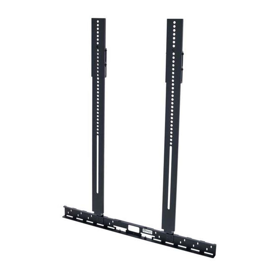
V I D E O B A R V B 1 D I S P L AY M O U N T I N G K I T
A
4.5 cm
(1.8 in)
65.0 cm
(25.6 in)
23.0 cm
C
D
(0.9 in)
(×2)
5.5 cm
(2.2 in)
1.8 cm
(0.7 in)
21.0 cm
(8.3 in)
INSTALLATION
1. Read the included Important Safety Instructions before continuing.
WARNING: Install this bracket only if the display will be fixed in place on a wall or to a cart. Do not install
this bracket on a display that will not be fixed in place, such as on a tabletop stand.
WARNING: Ensure the wall-mount bracket or cart (to which the display will be installed) is rated for the
additional weight of this display mounting kit and the Bose Videobar VB1.
2. If the display is already mounted on the wall, detach the display from its wall-mount bracket, and save
the original hardware.
3. Insert the tab of each vertical bracket (B) to a slot of the horizontal bracket (A).
Notes:
• The brackets may be assembled so the VB1 is above or below the display.
• The two bolts on the horizontal bracket (aligned with the hinged tabs of the VB1) must face upward
when the installation is complete.
• The flat side of the horizontal bracket may face toward or away from the VB1 as long as the two
slots for the hinged tabs of the VB1 point downward.
• The vertical brackets should be equally distant from the center of the horizontal bracket.
• The vertical brackets should align with the mounting points of the display and the holes in the
wall-mount bracket.
4. Use two of the included M4 screws (D) to attach the tab of each vertical bracket (B) to the horizontal
bracket (A) (four screws total).
5. If the upper two mounting points of the display are more than 628 mm (24.7 in) above the bottom edge
of the display, attach the extension brackets (C) to the vertical brackets (B) using four of the included
M4 screws (D) (eight screws total). The extension brackets will extend the usable length of the vertical
brackets up 140 mm (5.5 in).
Notes:
•
The extension brackets should increase the length of the vertical brackets by equal amounts.
•
The holes in the center of each extension bracket should be aligned with the holes in the center of
each vertical bracket.
6. Insert the hinged tabs of the VB1 into the two slots near the center of the horizontal bracket (A). Use an
included M4 nut (E) to attach each hinged tab to the bolt in front of each slot.
7. Place the vertical brackets (B) (and extension brackets, if applicable) between the rear panel of the display
and the wall-mount bracket of the display. Align the holes of the display, vertical brackets (or extension
brackets), and wall-mount bracket, and (re)attach them using the appropriate hardware. (Make sure the
bottom edge of the display is approximately aligned with the flange of the vertical brackets.)
INSTALACIÓN
1. Lea las Instrucciones importantes de seguridad incluidas antes de continuar.
ADVERTENCIA: Instale este soporte únicamente si la pantalla estará fija en una pared o un carro. No
instale este soporte en una pantalla que no estará fija, como en un soporte de mesa.
ADVERTENCIA: Asegúrese de que el soporte para pared o el carro (en el que se instalará la pantalla)
cuenten con la clasificación necesaria para soportar el peso adicional de este kit de montaje de pantalla y
la Bose Videobar VB1.
2. Si la pantalla ya está instalada en la pared, quítela del soporte para pared y guarde los accesorios originales.
3. Inserte la lengüeta de cada soporte vertical (B) en una ranura del soporte horizontal (A).
Notas:
• Los soportes se pueden armar de modo que la VB1 se instale por encima o por debajo de la pantalla.
• Los 2 pernos del soporte horizontal (alineados con las lengüetas articuladas de la VB1) deben estar
orientados hacia arriba cuando se complete la instalación.
• El lado plano del soporte horizontal puede estar orientado hacia la VB1 o hacia el lado opuesto,
siempre que las 2 ranuras de las lengüetas articuladas de la VB1 apunten hacia abajo.
• Los soportes verticales deben estar a la misma distancia del centro del soporte horizontal.
• Los soportes verticales deben alinearse con los puntos de montaje de la pantalla y los orificios del
soporte para pared.
4. Utilice 2 de los tornillos M4 incluidos (D) para fijar la lengüeta de cada soporte vertical (B) en el soporte
horizontal (A) (4 tornillos en total).
5. Si los 2 puntos de montaje superiores de la pantalla están a más de 628 mm (24.7") del borde inferior
de la pantalla, fije los soportes de ampliación (C) en los soportes verticales (B) con 4 de los tornillos M4
incluidos (D) (8 tornillos en total). Los soportes de ampliación extenderán la longitud utilizable de los
soportes verticales hasta 140 mm (5.5").
Notas:
• Los soportes de ampliación deben aumentar la longitud de los soportes verticales en cantidades iguales.
• Los orificios en el centro de cada soporte de ampliación deben alinearse con los orificios en el centro
de cada soporte vertical.
6. Inserte las lengüetas articuladas de la VB1 en las 2 ranuras cerca del centro del soporte horizontal (A).
Utilice una tuerca M4 incluida (E) para fijar cada lengüeta articulada al perno delante de cada ranura.
7. Ubique los soportes verticales (B) (y los soportes de ampliación, si corresponde) entre el panel posterior de
la pantalla y el soporte para pared. Alinee los orificios de la pantalla, los soportes verticales (o los soportes
de ampliación) y el soporte para pared, y vuelva a fijarlos con los accesorios adecuados. (Asegúrese de que
el borde inferior de la pantalla esté aproximadamente alineado con la brida de los soportes verticales).
B
(×2)
5.0 cm
(2.0 in)
2.3 cm
(0.9 in)
70.4 cm (27.7 in)
E
V I D E O B A R V B 1 D I S P L AY M O U N T I N G K I T
(×12)
(×2)
Installation Guide
M4
M4
INSTALLATION
1. Avant de continuer, lisez les Instructions importantes relatives à la sécurité incluses.
AVERTISSEMENT : n'installez ce support que si l'écran doit être fixé sur un mur ou sur un chariot. N'installez
pas ce support sur un écran qui ne sera pas fixé dans un endroit fixe, par exemple sur un support de table.
AVERTISSEMENT : assurez-vous que le support mural ou le chariot (sur lequel l'écran sera installé) est
adapté au poids supplémentaire de ce kit de fixation d'écran et de la barre de son Bose Videobar VB1.
2. Si l'écran est déjà fixé au mur, détachez l'écran de son support mural et conservez le matériel d'origine.
3. Insérez la languette de chaque support vertical (B) dans une fente du support horizontal (A).
Remarques :
• Les supports peuvent être assemblés de manière à ce que la barre de son VB1 se trouve au-dessus
ou en dessous de l'écran.
• Les deux boulons du support horizontal (alignés avec les languettes articulées de la VB1) doivent
être orientés vers le haut lorsque l'installation est terminée.
• Le côté plat du support horizontal peut être orienté vers la VB1 ou à l'opposé de celle-ci, tant que les
deux fentes pour les languettes articulées de la VB1 sont orientées vers le bas.
• Les supports verticaux doivent être à égale distance du centre du support horizontal.
• Les supports verticaux doivent être alignés avec les points de fixation de l'écran et les orifices du
support mural.
4. Utilisez deux des vis M4 incluses (D) pour fixer la languette de chaque support vertical (B) au support
horizontal (A) (quatre vis au total).
5. Si les deux points de montage supérieurs de l'écran se trouvent à plus de 628 mm au-dessus du bord
inférieur de l'écran, fixez les supports d'extension (C) aux supports verticaux (B) à l'aide de quatre des
vis M4 (D) incluses (huit vis au total). Les supports d'extension augmentent la longueur utilisable des
supports verticaux de 140 mm.
Remarques :
• Les supports d'extension doivent augmenter la longueur des supports verticaux d'une valeur égale.
• Les orifices au centre de chaque support d'extension doivent être alignés avec les orifices au centre
de chaque support vertical.
6. Insérez les languettes articulées de la barre de son VB1 dans les deux fentes situées près du centre du
support horizontal (A). Utilisez un écrou M4 (E) fourni pour fixer chaque languette articulée au boulon
situé devant chaque fente.
7. Placez les supports verticaux (B) (et les supports d'extension, le cas échéant) entre le panneau arrière
de l'écran et le support mural de l'écran. Alignez les orifices de l'écran, des supports verticaux (ou des
supports d'extension) et du support mural, et fixez-les (à nouveau) à l'aide du matériel approprié. (Veillez
à ce que le bord inférieur de l'écran soit à peu près aligné avec le rebord des supports verticaux.)
INSTALLATION
1. Bitte lesen Sie die beiliegenden Wichtigen Sicherheitshinweise, bevor Sie fortfahren.
WICHTIGER HINWEIS: Installieren Sie diese Halterung nur, wenn das Display fest an einer Wand oder
einem Rollwagen angebracht ist. Bringen Sie sie nicht an einem Display an, das flexibel positionierbar ist
und beispielsweise auf einem Tisch aufgestellt wird.
WICHTIGER HINWEIS: Stellen Sie sicher, dass die Wandhalterung oder der Rollwagen, an dem das
Display befestigt werden soll, für das Gesamtgewicht dieses Display-Montagesets und der Bose
Videobar VB1 geeignet ist.
2. Wenn das Display bereits an der Wand angebracht wurde, entfernen Sie es von der Wandhalterung und
bewahren Sie das Montagematerial sorgfältig auf.
3. Stecken Sie die Laschen der vertikalen Halterungen (B) jeweils in einen der Schlitze an der horizontalen
Halterung (A).
Anmerkungen:
• Die Halterungen können so angebracht werden, dass sich die VB1 über oder unter dem Display befindet.
• Nach Abschluss der Installation müssen die zwei Schrauben der horizontalen Halterung an den
ausklappbaren Laschen der VB1 ausgerichtet sein und nach oben zeigen.
• Die flache Seite der horizontalen Halterung kann zur VB1 zeigen oder von ihr weg, vorausgesetzt die
zwei Schlitze für die ausklappbaren Laschen der VB1 zeigen nach unten.
• Die vertikalen Halterungen sollten in gleichem Abstand vom Mittelpunkt der horizontalen Halterung
angebracht werden.
• Zudem sollten sie an den Befestigungspunkten des Displays und den Löchern in der Wandhalterung
ausgerichtet sein.
4. Befestigen Sie die Laschen der vertikalen Halterungen (B) jeweils mit zwei der mitgelieferten M4-
Schrauben (D) (vier Schrauben insgesamt) an der horizontalen Halterung (A).
5. Wenn sich die oberen zwei Befestigungspunkte des Displays mehr als 628 mm über der Unterkante
des Displays befinden, bringen Sie die Erweiterungshalterungen (C) mit jeweils vier der mitgelieferten
M4-Schrauben (D) (acht Schrauben insgesamt) an den vertikalen Halterungen (B) an. Mit den
Erweiterungshalterungen lassen sich die vertikalen Halterungen um bis zu 140 mm verlängern.
Anmerkungen:
• Achten Sie darauf, beide vertikalen Halterungen mit den Erweiterungshalterungen genau gleich weit
zu verlängern.
• Die Löcher in der Mitte der Erweiterungshalterungen sollten genau über den Löchern in den
vertikalen Halterungen positioniert werden.
6. Stecken Sie die ausklappbaren Laschen der VB1 in die zwei Schlitze in der Mitte der horizontalen
Halterung (A). Befestigen Sie die ausklappbaren Laschen mit je einer der mitgelieferten M4-Muttern (E)
an der Schraube vor dem entsprechenden Schlitz.
7. Positionieren Sie die vertikalen Halterungen (B) (und Erweiterungshalterungen, falls zutreffend) zwischen
der Rückseite des Displays und der Wandhalterung. Richten Sie die Löcher des Displays, der vertikalen
Halterungen (oder Erweiterungshalterungen) und der Wandhalterung korrekt aus und befestigen Sie sie
mit dem entsprechenden Montagematerial. (Achten Sie darauf, dass die Unterkante des Displays und der
Flansch der vertikalen Halterungen korrekt aneinander ausgerichtet sind.)
a
V I D E O B A R V B 1
D I S P L AY M O U N T I N G K I T
Important Safety
Instructions
V I D E O B A R V B 1
D I S P L AY M O U N T I N G K I T
Important Safety
Instructions
e
628 mm
>
(24.7 in)
(×2)
(×2)
140 mm
<
(5.5 in)
D
C
D
B
Installation Guide
Guía de instalación
Notice d'installation
Installationsanleitung
b
c
B
f
g
> 20 mm
(0.8 in)
A
B
E
E
Guida all'installazione
安装指南
Installatiehandleiding
安裝指南
Monteringsveiledning
設置ガイド
Instrukcja montażu
دليل التركيب
200 mm (7.9 in)
300 mm (11.8 in)
400 mm (15.7 in)
500 mm (19.7 in)
600 mm (23.6 in)
B
A
d
(×2)
D
B
B
A
A
B
©2020 Bose Corporation, All rights reserved.
Framingham, MA 01701-9168 USA
PRO.BOSE.COM
AM864717 Rev. 00
November 2020
Advertisement

Related Manuals for Bose 842888-0010


Summary of Contents for Bose 842888-0010
- Page 1 Bose Videobar VB1. adapté au poids supplémentaire de ce kit de fixation d’écran et de la barre de son Bose Videobar VB1. 2. If the display is already mounted on the wall, detach the display from its wall-mount bracket, and save 2.
- Page 2 2. Jeśli ekran jest już zamontowany na ścianie, należy zdjąć go z uchwytu ściennego i zachować oryginalne .اقرأ اإلرشادات الهامة حول السالمة المض م ّنة قبل المتابعة geïnstalleerd) geschikt is voor het extra gewicht van deze montageset en de Bose Videobar VB1. 警告:請確認欲安裝顯示幕的壁掛支架或推車能夠承受此顯示幕安裝套件及 Bose części.