Table of Contents
Advertisement
Advertisement
Table of Contents

Related Manuals for Midea PH Series


Summary of Contents for Midea PH Series
- Page 1 MIDEA 50Hz PORTABLE PH SERIES...
-
Page 2: Table Of Contents
CONTENTS 1. Precaution ............................. 1 1.1 Safety Precaution..........................1 1.2 Warning ............................... 1 2. Model Lists ............................6 3. Function and control panel ......................... 6 3.1 Function .............................. 6 3.2 Control panel ............................7 ... -
Page 3: Precaution
1. Precaution 1.1 Safety Precaution. To prevent injury to the user or other people and property damage, the following instructions must be followed. Incorrect operation due to ignoring instruction will cause harm or damage. Before service unit, be sure to read this service manual at first. 1.2 Warning ... - Page 4 It may cause injury, accident, or damage to the product. Be sure the installation area does not deteriorate with age. If the base collapses, the air conditioner could fall with it, causing property damage, product failure, and personal injury. ...
- Page 5 unit is so equipped.) There is risk of physical injury, electric shock, or product failure. When the product is soaked (flooded or submerged), contact an Authorized service center. There is risk of fire or electric shock. Be caution that water could not enter the product. There is risk of fire, electric shock, or product damage.
- Page 6 Operational Do not expose the skin directly to cool air for long periods of time. (Do not sit in the draft). This could harm to your health. Do not use the product for special purposes, such as preserving foods, works of art, etc. It is a consumer air conditioner, not a precision refrigerant system There is risk of damage or loss of property.
- Page 7 Warning -Do not use means to accelerate the defrosting process or to clean, other than those recommended by the manufacturer. -The appliance shall be stored in a room without continuously operating ignition sources (for example: open flames, an operating gas appliance or an operating electric heater). -Do not pierce or burn.
-
Page 8: Model Lists
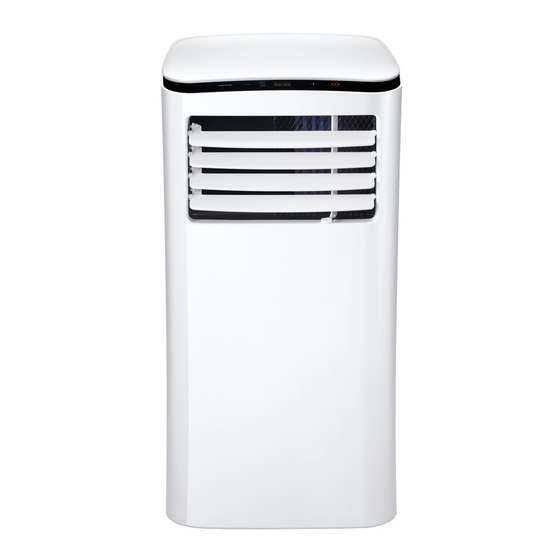
2. Model Lists Capacity(Btu/h) Model MPPHA-05CRN7-QB6 MPPH-07CRN7-QB6G1 MPPHA-07CRN7-QB6 ON/OFF MPPH-08CRN7-QB6 MPPHB-08CRN7-QB6-N MPPH-09CRN7-QB6 MPPHB-09CRN7-QB6-N 3. Function and control panel 3.1 Function ※ Operation mode: Cooling, Dry Fan-only and Auto. ※ Auto swing function ※ Timer function ※ No bucket design. ※... -
Page 9: Control Panel
3.2 Control panel ① Mode select button Selects the appropriate operating mode. Each time you press the button, a mode is selected in a sequence that goes from COOL, DRY, FAN.The mode indicator light illuminates under the different mode setting ②... - Page 10 If error repeats, call for service. EC- Refrigerant leakage detection malfunction- Unplug the unit and plug it back in. If error repeats, call for service. Protection codes: P1- Bottom tray is full - Connect the drain hose and drain the collected water away. If error repeats, call for service ⑤...
-
Page 11: Dimension
4. Dimension Capacity(Btu/h) W(mm) H(mm) D(mm) small body big body... -
Page 12: Refrigerant Cycle Diagram
5. Refrigerant Cycle Diagram The figure below is a brief description of the important components and their function in what is called the refrigeration system. This will help to understand the refrigeration cycle and the flow of the refrigerant in the cooling cycle. CAPILIARY TUBE LIQUID SIDE CONDENSER... -
Page 13: Wiring Diagram
6. Wiring Diagram MPPHA-05CRN7-QB6, MPPH-07CRN7-QB6G1, MPPH-08CRN7-QB6, MPPH-09CRN7-QB6... - Page 14 MPPHA-07CRN7-QB6, MPPHB-08CRN7-QB6-N, MPPHB-09CRN7-QB6-N...
-
Page 15: Electronic Function
7 Electronic function 7.1 Terms and definitions TC: Temperature of evaporator (T2). TA: Temperature of indoor ambient (T1). TS: The set temperature. TE: Temperature of condenser (T3) 7.2 Electric Control working environment Input voltage: 187~264V for 50Hz models and 97~127V for 60Hz models; 7.3 Protection function ... -
Page 16: Drying Mode
7.5.2.1 If TA﹥TS+1℃, the two fans operate. After 15 seconds, the compressor operates. 7.5.2.2 If TA≤TS after the compressor operates, this compressor will stop, and two fans last for working all the time. 7.5.3 Auto fan acts as below rules: 7.5.5. -
Page 17: Some Standard Functions Synopsis
7.7 Some standard functions synopsis 7.7.1. Timer function When the unit is on, firstly press the Timer button, the TIMER OFF indicator light illuminates. It indicates the Auto Stop program is initiated. When the unit is off, firstly press the Timer button, the TIMER ON indicator light illuminates. -
Page 18: Installation Details
8 Installation details 8.1 Installation instructions Location Your installation location should meet the following requirements: -Make sure that you install your unit on an even surface to minimize noise and vibration. -The unit must be installed near a grounded plug, and the Collection Tray Drain (found on the back of the unit) must be accessible. - Page 19 Type wall installation: Step 2: Install the Exhaust hose assembly to the unit Push the Exhaust hose into the airoutlet opening of the unit along the arrow direction. Step 3:Preparing the Adjustable Window Slider 1. Choose the window sliders according the size of your window. Sometimes, it needs to be cut short to meet the window size, please take extra care to cut it properly.
- Page 20 2. Use bolts to fasten the window sliders once they are adjusted to the Proper length.
- Page 21 Exhaust Hose Installation Note: Once the Exhaust Hose assembly and Adjustable Window Slider are prepared, choose from one of the following two installation methods. Type 1: Hung Window Installation or or Sliding Window Installation(For some models) 1. Cut the adhesive foam seal A and B strips to the proper lengths, and attach them to the window sash and frame as shown.
- Page 22 2. Insert the window slider assembly into the window opening. 3. Cut the non-adhesive foam seal C strip to match the width (or height) of the window. Insert the seal between the glass and the window frame to prevent air and insects from getting into the room 4.
-
Page 23: Care And Maintenance
NOTE: To ensure proper function, DO NOT overextend or bend the hose. Make sure that there is no obstacle around the air outlet of the exhaust hose (in the range of 500mm) in order to the exhaust system works properly. All the illustrations in this manual are for explanation purpose only. Your air conditioner may be slightly different. - Page 24 3) Do not wash the unit directly under a tap or using a hose. It may cause electrical danger. 4) If the power cord is damaged, it should be repaired by manufacture or its agency. 1. Air filter Clean the air filter at least once every two weeks to prevent inferior fan operation because of dust Removal Grasp the air filter tab, pull the filter “out”...
-
Page 25: Basic Test Procedure
9 Basic test procedure 9.1 Defective compressor Compressors are single phase, depending on the model unit. All compressor motors are permanent split capacitor type using only a running capacitor across the start and run terminal. All compressors are internally spring mounted and externally mounted on rubber isolators. 9.1.1 Compressor wiring test Remove compressor terminal box cover and disconnect wires from terminals. - Page 26 9.1.3 Checking the compressor efficiency The reason for compressor inefficiency is normally due to broken or damaged suction and/or discharge valves, reducing the ability of the compressor to pump refrigerant gas. This condition can be checked as follows: 1. Install a piercing valve on the suction and discharge or liquid process tube. 2.
-
Page 27: Sealed Refrigeration System Repairs
the motor windings to sense the winding temperature and/or current draw. The overload is connected in series with the common motor terminal. Should the internal temperature and/or current draw become excessive; the contacts in the overload will open, turning off the compressor? The overload will automatically reset, but may require several hours before the heat is dissipated. - Page 28 9.2.3 Hermetic compressor replacement. The following procedure applies when replacing components in the sealed refrigeration circuit or repairing refrigerant leaks. (Include Compressor, condenser, evaporator, capillary tube, refrigerant leaks, etc.) 1. Recover the refrigerant from the system at the process tube located on the high side of the system by installing a line tap on the process tube.
-
Page 29: Fan Motor
2. Remove compressor, capillary tube and filter drier from the system. 3. Flush evaporator condenser and all connecting tubing with dry nitrogen or equivalent, to remove all contamination from system. Inspect suction and discharge line for carbon deposits. Remove and clean if necessary. -
Page 30: Capacitor
2. Disconnect fan motor wires from fan speed switch or system switch. 3. Apply "live" test cord probes on black wire and common terminal of capacitor. Motor should run at high speed. 4. Apply "live" test cord probes on red wire and common terminal of capacitor. Motor should run at low speed. -
Page 31: Characteristic Of Temperature Sensor
then gradually move back to infinity. 4. Reverse the leads of the probe and momentarily touch the capacitor terminals. The deflection of the pointer should be two times that of the first check if the capacitor is good. 5. Repeat steps 3 and 4 to check fan motor capacitor. NOTE: A shorted capacitor will indicate a low resistance and the pointer will move to the "0"... -
Page 32: Troubleshooting
11 Troubleshooting In general, possible trouble is classified in three kinds. One is called Starting Failure which is caused from an electrical defect, another is ineffective Air Conditioning caused by a defect in the refrigeration circuit and improper application, and the other is called the Structure Damage. TROUBLES POSSIBLE CAUSES SUGGEST REMEDIES... -
Page 33: Error Codes And Solution
Error codes and Solution E1---Room temperature sensor error. E2---Evaporator temperature sensor error. Causation: a) Port of temperature sensor is loose. b) Temperature sensor is bad. c) Circuit component is bad. Solution: a) Check the connection between temperature sensor and adaptor is ok, if not, please make sure the port plugs into the adaptor hard. - Page 34 a) Power off, then restart If it can not resume after 2 minutes, please replace the display PCB. EC--- Refrigerant Leakage Detection Causation: Define the evaporator coil temp.T2 of the compressor just starts running as Tcool. In the beginning 5 minutes after the compressor starts up, if T2 <Tcool-1℃ does not keep continuous 4 seconds and this situation happens 3 times, the display area will show “EC”...