Table of Contents
Advertisement
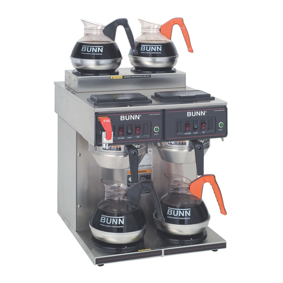
OPERATING & SERVICE MANUAL
10737.0000M 08/06 ©1993 Bunn-O-Matic Corporation
O N
O N
T
A
N
K
O FF
O FF
P
TO
AR
T
ST
R
WE
ON
/LO
!
N
N
ER
ER
IO
IO
NT
NT
U T
U T
CA
CA
C A
C A
D DE
D
DE
AR
AR
DI SC
DI
SC
IF :
IF :
KE
KE
D
D
D
D
Y
Y
AC
AC
HE
HE
Y
Y
PT
PT
E
E
. CR
. CR
RA
RA
D
TC
D
TC
DR
DR
EN
EN
EM
EM
AM
AM
IC
IC
. SC
. SC
ILE
ILE
WH
WH
H
H FL
FL
EC
EC
TR
TR
. BO
. BO
AT
AT
ED
ED
D
D EL
HIG
HIG
EL
. HE
. HE
ED
ED
ON
ON
SE
SE
. US
. US
EX
EX
PO
PO
TS
TS
. OR
. OR
EN
EN
RY
RY
EL
EL
EM
EM
S IN
S IN
JU
JU
ION
ION
RAT
RAT
RI
RI
SK
SK
CO
CO
RPO
RPO
LY
LY
-MA
-MA
TIC
TIC
MP
MP
N-O
N-O
CO
CO
5 BUN
5 BUN
E TO
E TO
198
198
IL UR
IL UR
FA
FA
658
658
PN:
PN:
BUNN-O-MATIC CORPORATION
POST OFFICE BOX 3227
SPRINGFIELD, ILLINOIS 62708-3227
PHONE: (217) 529-6601
CWT TWIN
CWTF TWIN
CWTF TWIN-APS
S
S
R
R
IE
IE
E
E
S
S
W
W
C
C
N
N
N
N
U
U
B
B
T
T
ST
ST
AR
AR
S
S
IE
IE
R
R
S
S
E
E
W
W
C
C
ON
ON
N
N
N
N
U
U
!
N
N
B
B
ER
ER
IO
IO
NT
NT
U T
U T
D DE
D DE
CA
CA
C A
C A
AR
AR
T
T
AR
AR
ST
ST
DI
DI SC
SC
IF:
IF:
D
D
KE
KE
HE
HE
D
D
PT
PT
Y
Y
. CR
. CR
AC
AC
TC
TC
D DR
DR
Y
Y
AM
AM
EM
EM
E
E
. SC
. SC
RA
RA
D
WH
WH
EN
EN
H
H
FL
FL
TR
TR
IC
IC
. BO
. BO
ILE
ILE
ED
ED
HIG
HIG
EL
EL
EC
EC
WE
WE
. HE
. HE
AT
AT
ON
ON
SE
SE
D
D
ON
ON
/LO
/LO
TS
TS
. US
. US
ED
ED
PO
PO
NT
NT
EN
EN
. OR
. OR
EX
EX
EN
EN
TS
TS
RY
RY
CO
CO
T
T
EL
EL
EM
EM
S IN
S IN
JU
JU
N
N
EL
EL
E HO
E HO
POR
POR
ATIO
ATIO
FU
FU
NN
NN
RI
RI SK
SK
COR
COR
AR
AR
LY
LY
-MA
-MA
TIC
TIC
MP
MP
N-O
N-O
TO
TO
CO
CO
198
198
5 BUN
5 BUN
RE
RE
ILU
ILU
FA
FA
658
658
PN:
PN:
N
N
ER
ER
IO
IO
NT
NT
U T
U T
CA
CA
C A
C A
D DE
D DE
AR
AR
DI
DI SC
SC
!
IF :
IF :
KE
KE
D
D
D
D
Y
Y
AC
AC
TC
TC
HE
HE
Y
Y
EM
EM
PT
PT
E
E
. CR
. CR
RA
RA
D
D
DR
DR
EN
EN
AM
AM
IC
IC
. SC
. SC
ILE
ILE
WH
WH
H
H
EC
FL
EC
FL
TR
TR
. BO
. BO
AT
AT
ED
ED
HIG
HIG
D
D
EL
EL
. HE
. HE
ED
ED
ON
ON
SE
SE
. US
. US
EX
EX
PO
PO
TS
TS
. OR
. OR
EN
EN
EL
EL
EM
EM
ION
ION
RAT
RAT
R
CO
CO
RPO
RPO
/LO
WE
-MA
-MA
TIC
TIC
ON
N-O
N-O
5 BUN
5 BUN
198
198
658
658
PN:
PN:
FAX: (217) 529-6644
www.bunn.com
Advertisement
Table of Contents

Related Manuals for Bunn CWT Twin


Summary of Contents for Bunn CWT Twin
- Page 1 5 BUN E TO E TO IL UR IL UR OPERATING & SERVICE MANUAL BUNN-O-MATIC CORPORATION PHONE: (217) 529-6601 10737.0000M 08/06 ©1993 Bunn-O-Matic Corporation CWTF TWIN-APS O FF O FF D DE D DE DI SC . CR . CR D DR .
- Page 2 SOLE OPTION AS SPECIFIED HEREIN, TO REPAIR, REPLACEMENT OR REFUND. In no event shall BUNN be liable for any other damage or loss, including, but not limited to, lost profi ts, lost sales, loss of use of equipment, claims of Buyer’s customers, cost of capital, cost of down time, cost of substitute equipment, facilities or services, or any other special, incidental or consequential damages.
- Page 3 USER NOTICES Carefully read and follow all notices in this manual and on the equipment. All labels on the equipment should be kept in good condition. Replace any unreadable or damaged labels. #00658.0000 #00831.0000 #00656.0000 #37881.0000 #12364.0000 10737 081706 Page 3...
-
Page 4: Electrical Requirements
ELECTRICAL REQUIREMENTS WARNING - The brewer must be disconnected from the power source until specifi ed in Initial Set-Up. Refer to Data Plate on the Brewer, and local/national electrical codes to determine circuit requirements. 120V. A.C. 208 or 240V. A.C. 120V. - Page 5 NOTE - Bunn-O-Matic recommends in the water line will facilitate moving the brewer to clean the countertop. Bunn-O-Matic does not recommend the use of a saddle valve to install the brewer. The size and shape of the hole made in the supply line by this type of device may restrict water fl...
- Page 6 CAUTION - The brewer must be disconnected from the power source throughout the initial set-up, except when specifi ed in the instructions. 1. Insert an empty funnel into the funnel rails. 2. Place an empty dispenser under the funnel. 3. Place the heater switch at the rear of the brewer in the "OFF" lower position. 4.
-
Page 7: Cleaning
Momentarily pressing and releasing the switch starts a brew cycle when the "ON/OFF" switch is in the "ON" upper position. NOTE – The "ON/OFF" switch must be in the "ON" upper position to initiate and complete a brew cycle. 1. Insert a BUNN ® fi lter into the funnel. - Page 8 A troubleshooting guide is provided to suggest probable causes and remedies for the most likely problems encountered. If the problem remains after exhausting the troubleshooting steps, contact the Bunn-O-Matic Technical Service Department. • Inspection, testing, and repair of electrical equipment should be performed only by qualifi ed service person- nel.
- Page 9 TROUBLESHOOTING (cont.) PROBLEM Brew cycle will not start (cont.) Water is not hot PROBABLE CAUSE 3. ON/OFF Switch 4. Start Switch 5. Timer 6. Solenoid Valve 7. Water strainer/flow control (.222 GPM) 1. Tank Heater Switch 2. Limit Thermostat CAUTION - Do not eliminate or bypass limit thermostat.
- Page 10 TROUBLESHOOTING (cont.) PROBLEM Inconsistent beverage level in dispenser Consistently low beverage level in the dispenser Spitting or excessive steaming PROBABLE CAUSE 1. Strainer/flow control (.222 GPM) 2. Syphon System 3. Lime Build-up CAUTION - Tank and tank compo- nents should be delimed regularly depending on local water condi- tions.
- Page 11 TROUBLESHOOTING (cont.) PROBLEM Spitting or excessive steaming (cont.) Dripping from sprayhead Water fl ows into tank continuously (ON/OFF Switch "ON") Water fl ows into tank continuously (ON/OFF Switch "OFF") Beverage overfl ows dispenser PROBABLE CAUSE 2. Control Thermostat 1. Syphon System 2.
- Page 12 A fi ne or drip grind must be used for proper extraction. A clean spray-head must be used for proper extraction. The BUNN ® paper fi lter must be centered in the funnel and the bed of ground leveled by gentle shaking.
- Page 13 TROUBLESHOOTING (cont.) PROBLEM Brewer is making unusal noises (cont.) Low beverage serving tempera- ture PROBABLE CAUSE 4. Tank Heater 1. Warmer Page 13 REMEDY Remove and clean lime off the tank heater. See page 21 Refer to Service - Warmer ele- ment for testing procedures.
-
Page 14: Table Of Contents
SERVICE This section provides procedures for testing and replacing various major components used in this brewer should service become necessary. Refer to Troubleshooting for assistance in determining the cause of any problem. WARNING - Inspection, testing, and repair of electri- cal equipment should be performed only by qualifi... -
Page 15: Control Thermostat
SERVICE (cont.) CONTROL THERMOSTAT FIG. 2 CONTROL THERMOSTAT Location: The control thermostats are located inside the trunk on the left side of the component brackets. Test Procedures: 1. Disconnect the brewer from the power source. 2. With a voltmeter, check the voltage across the blue wire on the control thermostat and the white insert on three pole 120/240 volt terminal... -
Page 16: Limit Thermostat
SERVICE (cont.) LIMIT THERMOSTAT FIG. 4 LIMIT THERMOSTAT Location: The limit thermostats are located inside the rear of the hood on the center rear of the tank lids. Test Procedures: 1. Disconnect the brewer from the power source. 2. Disconnect the blue and black wires from the limit thermostat. - Page 17 SERVICE (cont.) ON/OFF SWITCHES (cont.) Test Procedure: 1. Disconnect the brewer from the power source. 2. Viewing the switch from the back remove the white or red wire from the upper terminal and the black wire from the center terminal. 3.
-
Page 18: Recovery Booster
SERVICE (cont.) RECOVERY BOOSTER RELAY (OPTIONAL 2/2 & 0/6 ONLY) FIG. 8 RECOVERY BOOSTER RELAY Location The recovery boosters are located inside the trunk on the center of the component brackets just above the solenoid valve. Test Procedures 1. Disconnect the brewer from the power source. 2. -
Page 19: Solenoid Valve (Inlet)
SERVICE (cont.) SOLENOID VALVES FIG. 10 SOLENOID VALVES Location: The solenoid valves are located inside the trunk on the lower center part of the component brackets. Test Procedures: 1. Disconnect the brewer from the power source. 2. Disconnect the white and black wires from the solenoid valve. -
Page 20: Start Switch (Brew)
SERVICE (cont.) START SWITCHES 0/2 Models 2/2 Models 4/2 Models 0/6 Models APS Models FIG. 12 START SWITCHES Location: The start switches are located on the front of the hood in the center of each switch panel. Test Procedure: 1. Disconnect the brewer from the power supply. 2. -
Page 21: Tank Heater
SERVICE (cont.) TANK HEATER FIG. 14 TANK HEATER Location: The tank heaters are located inside the tank and secured to the tank lid. Test Procedures: 1. Disconnect the brewer from the power supply. 2. With a voltmeter, check the voltage across black and red wires on the tank heater. -
Page 22: Tank Heater Switch
SERVICE (cont.) TANK HEATER (Cont.) 6. Remove sprayhead and the hex nut securing the sprayhead tube to the hood. Set aside for reas- sembly. 7. Remove the eight #8-32 nuts securing the tank lid to the tank. 8. Remove the tank lid with limit thermostat, spray- head tube, tank heater, coil assembly and control thermostat w/bracket (early models only). - Page 23 SERVICE (cont.) Diagrams and check the brewer wiring harness. 5. Check for continuity between the black wire re- moved from the limit thermostat and the black insert on the terminal block. with the tank heater switch in the "ON" upper position. Continuity should not be present in the "OFF"...
-
Page 24: Timer (Early Models)
SERVICE (cont.) TIMERS (Early Models) FIG. 19 TIMERS Location: The timers are located inside the front of the trunk on the upper right side of component brack- ets. Test Procedure. 1. Disconnect the brewer from the power source. 2. Disconnect the polarized, three pin connector from the brewer wiring harness and rotate the brew timer dial fully counterclockwise. -
Page 25: Digital Timer (Late Models)
SERVICE (cont.) DIGITAL BREW TIMER (Late Models) FIG. 21 DIGITAL BREW TIMER Location: The timers are located inside the front of the trunk on the upper right side of the component brackets. Test Procedure. NOTE: Do not remove or install wires while timer board is installed. - Page 26 SERVICE (cont.) DIGITAL BREW TIMER (Late Models)(cont.) 1. Modifying brew volumes. To modify a brew vol- ume, fi rst check that the SET/LOCK switch is in the "SET" position on the circuit board. To increase a brew volume, place the ON/OFF switch in the "ON"...
-
Page 27: Warmer Element
SERVICE (cont.) WARMER ELEMENTS (Not used on APS Models) D IS D IS IF : IF : . CR . CR N EM W HE W HE H FL H FL . SC . SC IL ED IL ED . BO . -
Page 28: Wiring Diagrams
SCHEMATIC WIRING DIAGRAM CWT/CWTF TWIN 0/2, 2/2, 4/2 & CWT TWIN-APS LT.LIMIT THERMOSTAT RT. LIMIT THERMOSTAT (NOT AVAILABLE ON CWT TWIN-APS) WHI/RED WHI/RED P1-2 WHI/GRN WHI/GRN P1-3 WHI/GRN P3-3 WHI/GRN MODELS 2/2 & 4/2 ONLY P4-2 P4-3 WHI/YEL WHI/YEL RIGHT TOP FRONT WARMER... - Page 29 SCHEMATIC WIRING DIAGRAM CWT TWIN 2/2 & 4/2 LT. LIMIT THERMOSTAT RT. LIMIT THERMOSTAT P1-2 WHI/RED WHI/RED P1-3 WHI/GRN WHI/GRN WHI/GRN P3-3 WHI/GRN MODELS 2/2 & 4/2 ONLY P4-2 P4-3 WHI/YEL WHI/YEL MODELS 4/2 ONLY P5-3 WHI/VIO WHI/VIO SW10 P5-2...
- Page 30 WHI/BLU WHI/GRN T1 T5 T3 T4 P3-2 RIGHT BREW TIMER OPTIONAL INDICATOR TIMER P5-1 P4-1 10741.0000G 08/03 © 1993 BUNN-O-MATIC CORPORATION Page 30 GREEN LEFT TANK HEATER RIGHT TANK HEATER WHI/ORA P2-1 BLU/BLK WHI/BLU P2-3 WHI/GRN T1 T5 T3 T4...
- Page 31 WHI/RED SW2-R SW4-L P2-2L BRN/BLK LEFT FRONT WARMER SW5-L P2-3L LEFT REAR WARMER 10847.0000C 12/00 © 1994 BUNN-O-MATIC CORPORATION READY INDICATOR (FAUCET SIDE) THERMAL SW. & THERMOSTAT SAFETY FUSE "KEEP WARM" HEATER READY INDICATOR SW. & THERMOSTAT "KEEP WARM" HEATER...
- Page 32 BRN/BLK BRN/BLK RIGHT FRONT WARMER SW10 P5-3 RIGHT REAR WARMER 120/240 VOLTS AC 3 WIRE SINGLE PHASE 27693.0000D 07/03 © 1996 BUNN-O-MATIC CORPORATION RECOVERY BOOSTER LT. READY INDICATOR (FAUCET) LT. SW. & THERMOSTAT THERMAL SAFETY FUSE K.1. N.O. RT. READY INDICATOR LEFT "KEEP WARM"...
- Page 33 P5-2 WHI/BRN WHI/BRN RIGHT TOP REAR WARMER 230 VOLTS AC 3 WIRE THREE PHASE 10736.0001G 02/06 © 1993 BUNN-O-MATIC CORPORATION TWIN 2/2, 4/2 & TWIN-APS LT. READY INDICATOR LT. SW. & THERMOSTAT RT. READY INDICATOR RT. SW. & THERMOSTAT P1-1...
- Page 34 WHI/RED P3-1 BLU/BLK WHI/BLU T1 T5 T3 T4 WHI/GRN P3-2 RIGHT BREW TIMER P4-1 P5-1 10736.0002J 12/00 © 1993 BUNN-O-MATIC CORPORATION Page 34 GRN/YEL LEFT TANK HEATER RIGHT TANK HEATER WHI/BLU WHI/GRN T1 T5 T3 P2-2 LEFT BREW TIMER 10737 120100...
- Page 35 LEFT TOP REAR WARMER SW10 P5-2 WHI/BRN WHI/BRN RIGHT TOP REAR WARMER 230 VOLTS AC 2 WIRE SINGLE PHASE 10736.0004A 02/06 © 2006 BUNN-O-MATIC CORPORATION LT. READY INDICATOR (FAUCET) THERMAL LT. SW. & THERMOSTAT SAFETY FUSE RT. READY INDICATOR RT. SW. & THERMOSTAT THERMOSTAT RIGHT "KEEP WARM"...