Table of Contents
Advertisement
Quick Links
Advertisement
Table of Contents

Related Manuals for Swann AMI Turbitrack


Summary of Contents for Swann AMI Turbitrack
- Page 1 A-96.250.231 / 130421 Operator’s Manual Firmware V6.24 and higher AMI Turbitrack...
- Page 2 For any technical question, contact your nearest Swan representative, or the manufacturer: Swan Analytische Instrumente AG Studbachstrasse 13 8340 Hinwil Switzerland Internet: www.swan.ch E-mail: support@swan.ch Document status AMI Turbitrack Operator’s Manual Title: A-96.250.231 Revision Issue June 2005 First Edition Jan. 2014 Update to FW release 5.42, main board V2.4 April 2016 Update to FW release 6.00, main board V2.5...
-
Page 3: Table Of Contents
AMI Turbitrack Table of Contents Safety Instructions .......... - Page 4 AMI Turbitrack Maintenance ........... 36 6.1.
-
Page 5: Safety Instructions
AMI Turbitrack Safety Instructions AMI Turbitrack–Operator’s Manual This document describes the main steps for instrument setup, opera- tion and maintenance. Safety Instructions General The instructions included in this section explain the potential risks associated with instrument operation and provide important safety practices designed to minimize these risks. -
Page 6: Warning Notices
AMI Turbitrack Safety Instructions 1.1. Warning Notices The symbols used for safety-related notices have the following meaning: DANGER Your life or physical wellbeing are in serious danger if such warn- ings are ignored. Follow the prevention instructions carefully. WARNING Severe injuries or damage to the equipment can occur if such warnings are ignored. - Page 7 AMI Turbitrack Safety Instructions Warning Signs The warning signs in this manual have the following meaning: Electrical shock hazard Corrosive Harmful to health Flammable Warning general Attention general A-96.250.231 / 130421...
-
Page 8: General Safety Regulations
AMI Turbitrack Safety Instructions 1.2. General Safety Regulations Legal The user is responsible for proper system operation. All precautions must be followed to ensure safe operation of the instrument. Requirements Spare Parts Use only official SWAN spare parts and disposables. If other parts are used during the normal warranty period, the manufacturer’s war-... -
Page 9: Product Description
AMI Turbitrack Product Description Product Description Application The AMI Turbitrack is used for the measurement of relative turbidity. It is applicable for natural water, filtering processes and the process- ing in water supply companies. Measuring Turbidity is a measure of how much of the light traveling through wa- ter is scattered by suspended particles. - Page 10 AMI Turbitrack Product Description Communica- USB Interface for logger download. tion Interface RS485 with Fieldbus protocol Modbus or Profibus DP (optional) HART interface Measuring The light beam emitted by the emitter LED [B] passes through the sample and is received by the through beam sensor [F]. Some light...
- Page 11 AMI Turbitrack Product Description On-line The sample flows through the sample inlet [B] and the sample inlet valve [C] into the measuring chamber [A], where the turbidity is mea- Operation sured. From there it flows though the pressure regulator [F] with which the sample flow can be regulated.
-
Page 12: Instrument Specification
AMI Turbitrack Product Description 2.1. Instrument Specification Power Supply AC variant: 100–240 VAC (± 10%) 50/60 Hz (± 5%) DC variant 10–36 VDC Power consumption: max. 35 VA Transmitter Housing: aluminum, with a protection degree of specifications IP 66 / NEMA 4X Ambient temperature: −10 to +50 °C... - Page 13 AMI Turbitrack Product Description Turbidimeter Instrument type: High precision nephelometer complying Specifications with ISO 7027 (EN 27027, DIN 38404) Measuring range: 0.000–100.0 NTU Precision: ± 0.001 FNU/NTU or 1% of reading (whichever is greater) Response Time: typically < 15 s (after sample entry at...
- Page 14 AMI Turbitrack Product Description Dimensions Panel: Dimensions: 280x850x200 mm Screws: 6 pieces, 5 or 6 mm diameter Weight: 7.6 kg 280 mm / 11.02" 254 mm / 10.00" Exit Enter AMI Turbitrack 30 mm / 1.18" A-96.250.231 / 130421...
-
Page 15: Instrument Overview
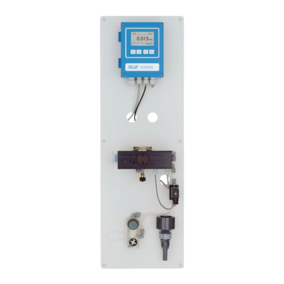
AMI Turbitrack Product Description 2.2. Instrument Overview Panel Solenoid valve Transmitter Drain funnel Cover measuring chamber Flow meter Sample outlet Pressure regulator valve Measuring chamber Sample inlet valve Cleaning outlet Humidity absorber Manual cleaning switch A-96.250.231 / 130421... -
Page 16: Installation
AMI Turbitrack Installation Installation 3.1. Installation Checklist AC variant: 100–240 VAC ( 10%), 50/60 Hz ( 5%) On-site require- DC variant: 10–36 VDC ments Power consumption: 35 VA maximum. Protective earth connection required. Sample line with a flow rate of 5–20 l/h and a maximum pressure of 10 bar. -
Page 17: Install The Ami Monitor
AMI Turbitrack Installation 3.2. Install the AMI Monitor The first part of this chapter describes the preparing and placing of the system for use. The instrument must only be installed by trained personnel. Mount the instrument in vertical position. -
Page 18: Fep Tube At Sample Outlet
3.3.3 Exchange capillary The AMI Turbitrack is as standard delivered with the capillary FEP tube with an inner diameter of 1 mm and a length of 500 mm. If you have a low sample pressure or you need a high sample flow, a shorter capillary with 186 mm length can be used. - Page 19 AMI Turbitrack Installation 3 Push in the knob to lock the valve in closed position. 4 Unscrew and remove the tube fittings [B] of the capillary [C]. 5 Then screw in the tube fittings of the 186 mm capillary. 6 Tighten them well.
-
Page 20: Electrical Connections
AMI Turbitrack Installation 3.4. Electrical Connections WARNING Electrical hazard. Always turn off power before manipulating electric parts. Grounding requirements: Only operate the instrument from an power outlet which has a ground connection. Make sure the power specification of the instrument corre- sponds to the power on site. - Page 21 AMI Turbitrack Installation WARNING External Voltage. External supplied devices connected to relay 1 or 2 or to the alarm relay can cause electrical shocks Make sure that the devices connected to the following contacts are disconnected from the power before resuming installation.
-
Page 22: Connection Diagram
AMI Turbitrack Installation 3.5. Connection Diagram CAUTION Use only the terminals shown in this diagram, and only for the mentioned purpose. Use of any other terminals will cause short circuits with possible corresponding consequences to material and personnel. A-96.250.231 / 130421... -
Page 23: Power Supply
Mains cable to comply with standards IEC 60227 or IEC 60245; flammable rating FV1 Mains equipped with an external switch or circuit-breaker – near the instrument – easily accessible to the operator – marked as interrupter for AMI Turbitrack A-96.250.231 / 130421... -
Page 24: Input
AMI Turbitrack Installation 3.7. Input Note: Use only potential-free (dry) contacts. The total resistance (sum of cable resistance and resistance of the relay contact) must be less than 50 Ω. Terminals 16/42 If signal output is set to hold, measurement is interrupted if input is active. -
Page 25: Relay Contacts 1 And 2
AMI Turbitrack Installation 3.8.2 Relay Contacts 1 and 2 Note: Rated load 1 AT / 250 VAC Relay 1 and 2 can be configured as normally open or as normally closed. Standard for both relays is normally open. To configure a Re- lay as normally closed, set the jumper in the upper position. - Page 26 AMI Turbitrack Installation CAUTION Risk of damage of the relays in the AMI Transmitter due to heavy inductive load. Heavy inductive or directly controlled loads (solenoid valves, dos- ing pumps) may destroy the relay contacts. To switch inductive loads > 0.1 A use an AMI relay box available as an option or suitable external power relays.
-
Page 27: Signal Outputs
AMI Turbitrack Installation 3.9. Signal Outputs 3.9.1 Signal Output 1 and 2 (current outputs) Note: Max. burden 510 Ω If signals are sent to two different receivers, use signal isolator (loop isolator). Signal output 1: Terminals 14 (+) and 13 (-) -
Page 28: Signal Output 3
AMI Turbitrack Installation 3.10.1 Signal Output 3 The AMI Turbitrack can display a maximum of two measured values: turbidity sample flow Therefore there is no need to install the optional third signal output. 3.10.2 Profibus, Modbus Interface Terminal 37 PB, Terminal 38 PA To connect several instruments by means of a network or to config- ure a PROFIBUS DP connection, consult the PROFIBUS manual. -
Page 29: Hart Interface
AMI Turbitrack Installation 3.10.3 HART Interface Terminals 38 (+) and 37 (-). The HART interface PCB allows for communication via the HART protocol. For detailed information, consult the HART manual. HART Interface PCB 3.10.4 USB Interface The USB Interface is used to store Logger data and for Firmware up- load. -
Page 30: Instrument Setup
AMI Turbitrack Instrument Setup Instrument Setup 4.1. Establish Sample Flow The pressure regulator valve only works if the inlet pressure at the main flow control valve is 0.5 bar higher than the outlet pressure. The 500 mm capillary tube reduces the pressure by a further 0.5 bar. -
Page 31: Run-In Period
AMI Turbitrack Instrument Setup 4.3. Run-in Period To assure correct measurement, run the instrument at least for 2 hours, better overnight to rinse out any pollution from transport and manufacturing and to adjust the temperature of the sample and the instrument. -
Page 32: Operation
AMI Turbitrack Operation Operation 5.1. Function of the Keys Exit Enter to exit a menu or command (rejecting any changes) to move back to the previous menu level to move DOWN in a menu list and to decrease digits to move UP in a menu list and to increase digits... -
Page 33: Measured Values And Symbols On The Display
AMI Turbitrack Operation 5.2. Measured Values and Symbols on the Display 15:20:18 2.53 35.8 l/h normal operation HOLD input closed or cal delay: Instrument on hold (shows status of signal outputs). input closed: Control/limit is interrupted (shows status of signal outputs). -
Page 34: Software Structure
AMI Turbitrack Operation 5.3. Software Structure Main Menu Messages Diagnostics Maintenance Operation Installation Menu 1: Messages Messages Reveals pending errors as well as an event history Pending Errors (time and state of events that have occurred at an Message List earlier point of time) and maintenance requests. -
Page 35: Changing Parameters And Values
AMI Turbitrack Operation 5.4. Changing Parameters and Values Changing The following example shows how to change the logger interval: parameters 1 Select the parameter you want to Sensors Logger 5.1.2 4.4.1 change. Sensor type FOME Log interval 30 min 2 Press [Enter] Disinf. -
Page 36: Maintenance
AMI Turbitrack Maintenance Maintenance 6.1. Maintenance Schedule Preventive maintenance frequency depends on water quality, on the application, and on national regulations. Every week Check sample flow. If necessary Clean the measuring chamber. When maintenance Replace the humidity absorber. message E068... -
Page 37: Cleaning The Test Unit
AMI Turbitrack Maintenance 2 Turn the lever located on the solenoid valve upwards to empty the flow cell. 3 Turn the cover [A] out of the bayonet connection and remove it from the measuring chamber [B]. 4 Clean the measuring chamber using a clean, soft tissue. -
Page 38: Replacing The Humidity Absorber
AMI Turbitrack Maintenance 6.4. Replacing the Humidity Absorber Dew point The instrument continuously measures the humidity and temperature inside the turbidimeter housing and calculates the dew point based calculation on these values. The dew point gives an indication of whether the humidity absorber still has sufficient capacity to prevent condensa- tion inside the housing. - Page 39 AMI Turbitrack Maintenance Replacement procedure Screw cover Bayonet lock cover with o-ring New humidity absorber flask Turbidimeter housing Saturated humidity absorber To replace the humidity absorber proceed as follows: 1 Select <Maintenance>/<Replace Absorber> and confirm with [Enter]. This makes the two messages E068 and E006 disappear for three days.
-
Page 40: Verification
AMI Turbitrack Maintenance 6 Screw the screw cover with the new humidity absorber flask into the measuring cell. 7 Tighten it well. Note: After replacing the humidity absorber, the dew point decreases only slowly. It may take several days until the dew point is below 3 °C again. - Page 41 AMI Turbitrack Maintenance To start a verification proceed as follows: 1 Navigate to menu <Maintenance>/ Maintenance <Verification> and press [Enter]. Verification 2 Stop sample flow. Rinsing Simulation 3 Empty measuring chamber by turning the lever on the solenoid Set Time 01.01.05 16:30:00 valve upwards.
-
Page 42: Longer Stop Of Operation
AMI Turbitrack Maintenance 6.6. Longer Stop of Operation Do not switch off the instrument if your operation is suspended for less than a week. Power consumption is very low and the turbidime- ter remains ready for use. If water hardness is very high, lime deposition may precipitate. -
Page 43: Troubleshooting
AMI Turbitrack Troubleshooting Troubleshooting 7.1. Error List Error Non-fatal error. Indicates an alarm if a programmed value is exceed- Such errors are marked E0xx (bold and black). Fatal error (blinking symbol) Control of dosing devices is interrupted. The indicated measured values are possibly incorrect. - Page 44 AMI Turbitrack Troubleshooting Error Description Corrective action – check process E001 Alarm high – check programmed value 5.3.1.1.1, p. – check process E002 Alarm low – check programmed value 5.3.1.1.25, p. – turbidity out of range E005 Range – disappears if measuring chamber is filled –...
- Page 45 AMI Turbitrack Troubleshooting Error Description Corrective action – check case/environment temperature E014 Case Temp. low – check programmed value 5.3.1.5, p. 60 – check control device or programming in E017 Control Timeout Installation, Relay contact, Relay 1 & 2 5.3.2 & 5.3.3, p. 61 –...
-
Page 46: Replacing Fuses
AMI Turbitrack Troubleshooting 7.2. Replacing Fuses WARNING External Voltage. External supplied devices connected to relay 1 or 2 or to the alarm relay can cause electrical shocks Make sure that the devices connected to the following contacts are disconnected from the power before resuming installation. -
Page 47: Program Overview
AMI Turbitrack Program Overview Program Overview For explanations about each parameter of the menus see Program List and Explanations, S. Menu 1 Messages informs about pending errors and mainte- nance tasks and shows the error history. Password protection possible. No settings can be modified. -
Page 48: Maintenance (Main Menu 3)
AMI Turbitrack Program Overview Sensors Turbidity * Menu numbers Turbidity FNU/NTU 2.2* 2.2.1* (Raw value) Quotient Scale Factor 1 Scale Factor 2 Miscellaneous 2.2.2.1* Case Temp. 2.2.2* 2.2.2.1* Dew point History Ver. History Number 2.2.3.1.1* 2.2.3* 2.2.3.1* Date, Time Actual value... -
Page 49: Operation (Main Menu 4)
AMI Turbitrack Program Overview Replace Absorber * Menu numbers Follow screen instructions 3.4* Set Time (Date), (Time) 3.5* 8.4. Operation (Main Menu 4) Sensors 4.1.1* Filter Time Const. 4.1* Hold after Cal. 4.1.2* Relay Contacts Alarm Relay Alarm Alarm High 4.2.1.1.1*... - Page 50 AMI Turbitrack Program Overview Relay Contacts Alarm Relay Alarm 5.3.1.1.1* Alarm High 5.3* 5.3.1* 5.3.1.1* Alarm Low 5.3.1.1.25 5.3.1.1.35 Hysteresis 5.3.1.1.45 Delay Sample Flow Flow Alarm 5.3.1.2.1* 5.3.1.2* 5.3.1.2.2* Alarm High 5.3.1.2.36* Alarm Low 5.3.1.4* Case Temp. high 5.3.1.5* Case Temp. low Relay 1 &...
-
Page 51: Program List And Explanations
Message list. 2 Diagnostics In diagnostics mode, the values can only be viewed, not modified. 2.1 Identification 2.1.1 Designation: of instrument: AMI Turbitrack 2.1.2 Version: firmware version, e.g. V6.24-01/20 2.1.3 Version TURBI3:, e.g. 1.01 2.1.4 Factory test: date of instrument, mainboard and frontend QC test. -
Page 52: Maintenance
AMI Turbitrack Program List and Explanations 2.2.2 Miscellaneous 2.2.2.1 Case Temp.: Temperature in °C inside the housing of the AMI trans- mitter. 2.2.2.1 Dew point: Calculated dew point in °C inside the housing of the turbidimeter. 2.2.3 History 2.2.3.1 Ver. history: Only for diagnostic purpose. Review the values of the last verifications. - Page 53 AMI Turbitrack Program List and Explanations 3.2 Rinsing 3.2.1 Manual operation Start rinsing manually at any time. 3.2.2 Automatic 3.2.2.1 Mode: The following modes are available: Interval daily weekly off 3.2.2.1 Mode Interval 3.2.2.201 Run time: The run time can be set in steps of 10 seconds from 30 –1800 seconds.
- Page 54 AMI Turbitrack Program List and Explanations 3.30 Simulation To simulate a value or a relay state, select the alarm relay, relay 1 and 2 signal output 1 and 2 with the [ ] or [ ] key.
-
Page 55: Operation
AMI Turbitrack Program List and Explanations 4 Operation 4.1 Sensors 4.1.1 Filter time constant: Used to damp noisy signals. The higher the filter time constant, the slower the system reacts to changes of the mea- sured value. Range: 5–300 sec 4.1.2... - Page 56 AMI Turbitrack Program List and Explanations 5.2 Signal Outputs 5.2.1 and 5.2.2 Signal Output 1 and 2: Assign process value, the current loop range and a function to each signal output. Note: The navigation in the menu <Signal Output 1> and <Signal Output 2>...
- Page 57 AMI Turbitrack Program List and Explanations [mA] 0 / 4 1’000 10’000 X Measured value (logarithmic) 5.2.1.40 Scaling: Enter beginning and end point (Range low & high) of the linear or logarithmic scale. In addition, the midpoint for the bilinear scale.
- Page 58 AMI Turbitrack Program List and Explanations As control Signal outputs can be used for driving control units. We distinguish different kinds of controls: output P-controller: The controller action is proportional to the devia- tion from the setpoint. The controller is characterized by the P- Band.
- Page 59 AMI Turbitrack Program List and Explanations Consult the manual of the control unit for connecting and program- ming details. Choose control upwards or downwards. Control upwards or downwards Setpoint: User-defined process value (Measured value or flow) P-Band: Range below (upwards control) or above (downwards con- trol) the set-point, within the dosing intensity is reduced from 100% to 0% to reach the set-point without overshooting.
- Page 60 AMI Turbitrack Program List and Explanations 5.3.1.1 Alarm 5.3.1.1.1 Alarm High: If the measured value rises above the alarm high value, the alarm relay is activated and E001, is displayed in the message list. Range: 0–250 FNU/NTU 5.3.1.1.25 Alarm Low: If the measured value falls below the alarm low value, the alarm relay is activated and E002 is displayed in the message list.
- Page 61 AMI Turbitrack Program List and Explanations 5.3.2 & 5.3.3 Relay 1 and 2: The contacts can be set as normally open or normal- ly closed with a jumper. See Relay Contacts 1 and 2, p. The function of relay contacts 1 and 2 is defined by the user.
- Page 62 AMI Turbitrack Program List and Explanations 5.3.2.1 Function = Control upwards/downwards:: The relays may be used to drive control units such as solenoid valves, membrane dosing pumps or motor valves. When driving a motor valve both relays are needed, relay 1 to open and relay 2 to close the valve.
- Page 63 AMI Turbitrack Program List and Explanations 5.3.2.32.4 Control Parameters: Range for each Parameter same as 5.2.1.43, p. 59 5.3.2.1 Function = Timer: The relay will be activated repetitively depending on the programmed time scheme. 5.3.2.24 Mode: Operating mode (interval, daily, weekly) 5.3.2.24...
- Page 64 AMI Turbitrack Program List and Explanations 5.3.2.24 daily The relay contact can be activated daily, at any time of a day. 5.3.2.341 Start time: to set the start time proceed as follows: 1 Press [Enter], to set the hours. 2 Set the hour with the [ ] or [ ] keys.
- Page 65 AMI Turbitrack Program List and Explanations 5.3.4 Input: The functions of the relays and signal outputs can be defined depending on the position of the input contact, i.e. no function, closed or open. 5.3.4.1 Active: Define when the input should be active: Input is never active.
- Page 66 AMI Turbitrack Program List and Explanations 5.4 Miscellaneous 5.4.1 Language: Set the desired language. Language German English French Spanish 5.4.2 Set defaults: Reset the instrument to factory default values in three different ways: Set defaults Calibration In parts Completely Calibration: Sets calibration values back to default. All other values are kept in memory.
- Page 67 AMI Turbitrack Program List and Explanations 5.4.5 Sample ID: Identify the process value with any meaning full text, such as KKS number. 5.4.6 Line Break Detection: Define if message E028 should be issued in case of a line break on signal output 1 or 2.
-
Page 68: Default Values
AMI Turbitrack Default Values Default Values Operation: Sensors: Filter Time Const.: ................30 s Hold after Cal.:................300 s Alarm Relay .................same as in Installation Relay 1 & 2 .................same as in Installation Input .................same as in Installation Logger: Logger Interval:................ 30 min Clear Logger:.................. - Page 69 AMI Turbitrack Default Values If Function = Control upw. or dnw: Parameter: ..............Meas. value Settings: Actuator: ............. Frequency Settings: Pulse Frequency: ..........120/min Settings: Control Parameters: Setpoint: ......100 FNU Settings: Control Parameters: P-band:......5.00 FNU Settings: Control Parameters: Reset time: ......... 0 s Settings: Control Parameters: Derivative Time: ......
-
Page 70: Index
AMI Turbitrack Index Index ..... . . Alarm Relay Measuring Principle .... -
Page 71: Notes
AMI Turbitrack Notes Notes A-96.250.231 / 130421... - Page 72 Swan Products - Analytical Instruments for: Swan is represented worldwide by subsidiary companies and distributors and cooperates with independent representatives all over the world. For contact in- formation, please scan the QR code. Swan Analytical Instruments ∙ CH-8340 Hinwil www.swan.ch ∙ swan@swan.ch AMI Turbitrack...