Advertisement
Quick Links
Read all instructions thoroughly
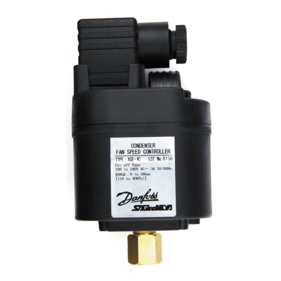
Installation Instructions: XGE Fan Speed Controller
IMPORTANT
Failure to read and follow all instructions carefully
before installing or operating this Fan Speed
Controller could cause personal injury and/or
property damage. Save these instructions for
future use.
NOTES FOR SAFETY
WARNING
Before wiring and service, be sure to turn off
power supply. Otherwise, may cause electrical
shock.
Before connection of a plug and disassembly of a
plug, be sure to turn off power supply as it may
cause electrical shock.
Do not touch the main body during driving.
Otherwise, it may burn a hands.
OUTLINE
The XGE controls Fan Motor Speed of air cooled
condenser of general purpose cold/ cooling unit by phase
control, and keeps a definite condensing pressure and
makes it to drive stably. Further, the XGE has a noise
filter, and is suitable to the following Council Directive of
European Communities.
ELECTROMAGNETIC COMPATIBILITY & SAFETY
FOR ELECTRICAL EQUIPMENT
As for the XGE, Saginomiya declared for the above
directives as follows.
1) Electromagnetic Compatibility
– Directives: 89/336/EEC, 92/31/EEC, 93/68/EEC
2) Safety for Electrical Equipment
– Directives: 73/23/EEC, 93/68/EEC
MOUNTING
Directly mount onto the pressure line (see Fig.1a) in a
location where pressure can be detected accurately (eg.
After the condenser) Alternatively it is possible to remote
mount to a side panel using the optional fixing bracket
(see fig. 8) and connect to the pressure line with a
refrigeration pipe (not supplied).
CAUTION
Don' t install at the place to require degrees of protection
over IP65 Category 2 enclosures.
Don' t tighten with excessive force whilst holding the unit,
Fig.1a
Einbauanfeitung genau durchlesenl
Typ XGE
Installation und Einstellanweisung: Drehzahlregler
WlCHTIG
N i c h t b e a c h t u n g o d e r N i c h t b e f o l g e n d e r
Einbauanleitung dieses Drehzahlreglers kann
Schaden an Personen und / oder Waren zur Folge
haben. Anleitung zur späteren Verwendung
aufbewahren.
SICHERHEITSANWEISUNGEN
WARNUNG
V o r V e r d r a h t u n g o d e r E i n g r i f f i m S y s t e m
sicherstellen, dass keine Spannung anliegt.
Nichtbeachten kann Elektroschock zur Folge
haben.
Vor Bedienung des Umschalters sicherstellen,
d a s s k e i n e S p a n n u n g a m G e r ä t a n l i e g t .
Nichtbeachten kann Elektroschock zur Folge
haben.
Wegen möglicher, hoher Gehäusetemperaturen,
den Drehzahlregler während des Betriebs nicht
berühren.
Anwendung
Der XGE regelt die Ventilatordrehzahl eines luftgekühlten
V e r f l ü s s i g e r e i n e r K ä l t e - / K l i m a a n l a g e d u r c h
P h a s e n a n s c h n i t t
u n d
h ä l t
d a d u r c h
Kondensationstemperatur in einem eingestellten Bereich
stabil.
Zudem besitzt der XGE einen Entstörfilter und entspricht-
den folgenden EC-Direktiven.
Elektromagnetische Verträglichkeit & Sicherheit für
elektrische Erzeugnisse
Saginomiya erklärt betreffend obenstehenden Richtlinien
folgendes :
1)Elektromagnetische Verträglichkeit
−Direktiven : 89/336/EEC, 92/31/EEC,
und Revision 93/68/EEC
2)Sicherheit für elektrische Erzeugnisse
−Direktive : 73/23/EEC, und Revision 93/68/EEC
INSTALLATION
Direkte Montage an einem Druckanschluss nach den
Verflüssiger (siehe Fig. 1a.) oder indirekte Montage auf
der Konsole (siehe Fig. 8). Einbaulage siehe Fig. 1b. Für
die korrekte Abdichtung der Verschraubung, ist ein
Kupferdichtring zu verwenden (siehe Fig. 2a).
ACHTUNG
Wird ein höherer Schutzgrad als IP65 gefordert sind
Maßnahmen zum Schutz des XGE erforderlich.
Den Messanschluss des XGE nicht mit Gewalt festziehen.
Benutzen Sie bitte einen passenden Maulschlüssel und
LEER TODAS ESTAS INSTRUCCIONES CON ATENCIÓN
Instrucciones de Instalación:
Control de velocidad ventilador XGE series.
IMPORTANTE
Dejar de leer y de seguir cuidadosamente todas
estas instrucciones, antes de instalar o hacer
funcionar este Controlador de Velocidad
Ventiladores, podría causar daños y/o perjuicios
adicionales.
Conserve estas instrucciones para necesidades
futuras.
NOTAS PARA SEGURIDAD
AVISO
A n t e s d e c a b l e a r y u s a r , a s e g u r a r s e d e
desconectar la tensión de alimentación. De lo
contrario, podrian recibirse descargas eléctricas.
Antes de accionar el Conmutador, asegurarse de
desconectar la tensión de alimentación, pues
podrian recibirse descargas eléctricas.
N o t o c a r o m a n i p u l a r e l c o n t r o l d u r a n t e e l
funcionamiento, podría aumentar la temperatura
de trabajo.
DESCRIPCION
Los XGE controlan la velocidad de los motores de
c o n d e n s a d o r e s e n f r i a d o s p o r a i r e , e n u n i d a d e s
enfriadoras de uso general, por medio del control de fase,
con lo que se mantiene la presión de
condensación determinada, con un funcionamiento
estable.
Además, el XGE tiene un filtro anti-ruido, y cumple con las
siguientes Directrices de la Comunidad Europea.
COMPATIBILIDAD ELECTROMAGNÉTICA Y
SEGURIDAD PARA EL EQUIPO ELÉCTRICO
Para el XGE, "SAGINOMIYA" declara lo siguiente en
relación a estas directrices:
1)Compatiblidad electromagnética
Directriz apropiada : 89/336/EEC, 92/31/EEC,
93/68/EEC
2)Sequridad para el equipo eléctrico
D i r e c t r i z a p r o p i a d a : 7 3 / 2 3 / E E C , y R e v i s i ó n
93/68/EEC
MONTAJE
El montaje del control puede ser directo en la línea de
presión (ver Fig.1a) en un punto donde la presión puede
ser detectada con precisión (Ej. a la salida de la unidad
condensadora). Alternativamente es posible instalar la
unidad en un panel aparte utilizado el brazo de montaje
opcional (ver Fig.8), seguidamente conectar al circuito o
línea de presión con un tubo adecuado para refrigeración
(no suministrado).
ADVERTENCIA
No montarlo en sitios que requieran grados de
protección superiores a IP65.
No sujetar la unidad con una fuerza excesiva ya que
podría dañar o deformar el control. Para el montaje al
circuito de refrigeración, utilizar la herramienta adecuada
ENGLISH
since this can result in deformation of the controller. For
direct mounting, tighten the connection using an
appropriately sized spanner and with a torque of 12.7 –
15Nm (see Fig.2).
The mounting position should be in the vertical axis and
should not be fitted more than 45 ° from the vertical (See
Fig.1b).
Failure to install the Copper Packing at the connection
portion cause leak of refrigerant gas.
Provide adequate ventilation space so that heat doesn' t
build up. At least 50mm clearance above the top and
below the bottom of XGE is necessary. Don' t mount this
instrument directly above equipment that generates large
amount of heat.
(heaters, transformers, large-wattage resistors.)
WIRING
Please refer to the diagram embossed on the controller
(see Fig.4) for use of correct terminals on the plug
(supplied). Connect Ground terminal to the earth line.
Please also make sure not to exceed the electrical rating
of the XGE when connecting to the fan motor. It is
possible to connect fan motors in parallel as long as the
rating is not exceeded. The plug can wired so that
orientation is possible in 4 directions as desired.
(see Fig. 6)
CAUTION
For connecting fan motor, use one phase 200 to 240V.
AC, one-phase induction motor which suited for phase
control and with heat preventing thermostat, or shaded
pole motor.
There is a case that the XGE does not control the fan
speed of the motor having large angle of its leading
current.
When connect with the power, make sure to use a Circuit
Breaker or a Fuse with the rated ampere or less of each
XGE model as shown by the cover.
Fix the plug onto the XGE, using the gasket provided and
securely tigthen with the screw (also provided) using a
torque of 0.4 – 0.6 Nm (see Fig. 5).
important to use the gasket (DIN 43650) between the plug
and controller as well as tigthening the screw sufficiently
to avoid the risk of electrical shock or short circuit.
When using a forced operation switch or fuse, make sure
to connect across terminals No.1 and No.2.
When a fan with selectable speed is being used, please
Fig.1b
45°
45°
DE UT SCH
ziehen Sie den Anschluss mit 12,7 - 15 Nm fest (siehe
Fig.2).
Einbaulage: Senkrecht (Elektroanschluss noch oben)
montieren. Maximale Neigung 45°(siehe Fig.1a).
Beiliegende Kupferdichtung montieren. Die Dichtheit der
Verbindung ist sonst nicht gewährleistet.
Für ausreichende Belüftung sorgen damit der XGE nicht
überhitzt. Nicht direkt an einer starken Wärmequelle
montieren. Mindestabstand von 50 mm ober- und
unterhalb des XGE einhalten.
VERDRAHTUNG
Bitte beachten Sie den Anschlussplan für ein korrekte
Verdrahtung (siehe Fig.4). Der Anschluss für Erde ist
entsprechend gekennzeichnet Es können zwei Motoren
parallel angeschlossen werden soweit die maximale
erlaubte Stromaufnahme des XGE nicht überschritten
wird. Der Stecker kann in 4 verschiedenen Positionen (je
90° gedreht) aufgesteckt werden (siehe Fig.6).
ACHTUNG
Die anzuschließenden Motoren sollten einphasig für den
Spannungsbereich 200 bis 240V und Induktions- oder
Spaltpolmotoren mit eingebautem Überlastungsschutz
sein.
Sollte der angeschlossene Motor einen sehr schlechten
cos φ haben ist es möglich dass der XGE nicht korrekt
d i e
funktioniert.
Der XGE ist separat abzusichern.
Bitte die beiliegende Unterlage (DIN 43650) für die
Abdichtung des Steckers zum Gehäuse verwenden und
den Stecker mit der Schraube (0,4 – 0,5 Nm) befestigen
(siehe Fig.5).
Bei Verwendung eines Lüftermotors mit wählbarer
Drehzahl, bitte unbedingt dessen korrekte Funktion in
Verbindung mit dem XGE prüfen.
Bei Verwendung eines Lüftermotors mit wählbarer
Drehzahl, bitte unbedingt dessen korrekte Funktion in
Verbindung mit dem XGE prüfen.
Bei der Verwendung von Ventilatormotoren (mit 4A) darf
die Umgebungstemperatur 40 °C[104° F] nicht überschreiten.
Ausführliche Angaben über "Zusammenhang zwischen
der Stromstärke und der Umgebungstemperatur"
entnehmen Sie bitte der Abbildung 10.
EINREGULIERUNG (Fig.3)
Die Einstellschraube nach rechts(+)gedreht, ergibt
Erhöhen des Einstellpunkts, nach links()ergibt
Absenken des Einstellpunkts.
Die Skala erleichtert die Einstellung
ESPA ÑO L
aplicando una fuerza de apriete de 12,7 a 15 Nm (Ver Fig
1a).
La posición de montaje debe ser en el plano vertical y no
debe exceder en un ángulo de inclinación máximo de 45º
desde el plano vertical.
Fallos en la colocación de la estopa de cobre al conector,
originarán fugas del gas refrigerante.
Disponer de un espacio de ventilación suficiente
alrededor del control XGE como mínimo 50 mm en el lado
s u p e r i o r e i n f e r i o r d e l c o n t r o l . N o i n s t a l a r e s t e
componente encima de otros equipos que generen mucho
calor tales como calefactores, transformadores y
resistencias de potencia elevada.
CABLEADO
Para el correcto conexionado de los cables eléctricos
se incluye un plano eléctrico en el control (Ver fig.4).
Asegurarse que no se excede la capacidad eléctrica
disponible en estos controles XGE cuando conectemos
el ventilador. Es posible conectar varios ventiladores
e n p a r a l e l o s i e m p r e y c u a n d o n o s e e x c e d a l a
capacidad eléctrica disponible. El conector eléctrico es
p o s i b l e o r i e n t a r l o e n 4 d i r e c c i o n e s s e g ú n s e a
necesario (Ver Fig 6).
ADVERTENCIA
El motor del Ventilador a conectar, ha de ser un motor de
inducción o un motor de polos sombreados(con bobina
de arranque), con térmico de protección incorporado y
que tenga la capacidad de contactos(o menos)de cada
modelo XGE, lo que es adecuado para el control de fase.
Puede ocurrir que el XGE no controle la velocidad del
ventilador, en el caso que éste tenga un gran ángulo de
corriente avanzada.
Al conectar a la corriente, asegurarse de utilizar un
Disyuntor o un Fusible con el valor en amperios(o
menos)de cada modelo XGE, tal como señalado en la
Tapa.
F i j a r e l c o n e c t o r e n e l c o n t r o l X G E m e d i a n t e l a
abrazadera suministrada y fijar con el tornillo también
suministrado con un par
de apriete recomendado de 0.4-0.6 Nm (Ver Fig 5)
PRECAUCION :Es importante utilizar la abrazadera (DIN
43650)
entre el conector eléctrico y el control así como el tornillo
de sujeción a modo de evitar riesgos de cortocircuito
eléctrico o daño eléctrico no deseado.
En caso de operación forzada o fusible, asegurarse de
conectar los terminales no. 1 y no. 2.
Cuando el ventilador utilizado dispone de selector de
velocidad, primero comprobar que el ventilador funciona
correctamente antes de conectar la unidad XGE,
seguidamente comprobar el funcionamiento en modo de
operación normal.
Con un motor ventilador de 4 Amp, la temperatura
ambiente no debe exceder los 40ºC[104º F]. Ver detalles
en fig 10, relación entre temperatura ambiente y corriente
electrica.
first check that the fan functions correctly after connecting
to the XGE, and before running in normal operating mode.
When using a 4A fan motor, the ambient temperature
should not exceed 40° C[104° F]. Please refer to Fig 10
for the details of "the relationship between electric current
and ambient temperature.
ADJUSTING (Fig.3)
Turn the Range
Adjusting Screw to
clockwise (+) for
increasing the setting value, and to counterclockwise (-)
for decreasing the setting value.
(Please use the right chart as reference for adjusting.)
CAUTION
Do not move the screw other than the Range Adjusting
Screw.
OPERATION CHECK
Install and calibrate the product correctly and then check
its operation to confirm correct function of the whole
system.
CAUTION
It can not be used for ammonia refrigeration system.
This product is not available for the system which apply
pressure more than 47bar[681Psi] because the rated
maximum working pressure of this product is 47bar
[681Psi] if the pressure more than the rated maximum
working pressure is applied to this product, it causes
transformation of characteristics or the destruction.
Operation will become unstable when using other than
sine waves for the power supply. In this case, proper
control may not be achieved.
SPECIFICATIONS
XGE-4C
XGE-4M
XGE-6C
XGE-6M
A m b i e n t T e m p e r a t u r e o f F a n S p e e d C o n t r o l l e r H o u s i n g : - 2 0 t o 5 5 ° C [ - 4 t o 1 3 1 ° F ] ( W i t h 4 A r a t e d f a n s :
4 0 ° C [ 1 0 4 ° F ] m a x i m u m a m b i e n t t e m p e r a t u r e . )
CAUTION: It is
F.V.S. : Full Voltage Set point
The pressure at which the control delivers 95% out put effective voltage. (R.M.S.(V%))
E.P.B. : Effective Proportional Band
The decrease in pressure below the calibration set point required to transmit a 45% of effective voltage. (R.M.S.(V%))
Fig.2a
Fig.2b
ACHTUNG
Nur die Klemmen- und Einstellschrauben verwenden.
FUNKTIONSPRÜFUNG
Nach korrekter Installation und Einstellung des XGE
Funktionsprüfung des Systems erforderlich.
ACHTUNG
Das Gerät ist nicht in Systeme mit Ammoniak einsetzbar.
Der maximale Betriebsdruck beträgt 47 bar (681 psi). Wird
der XGE mit einem höheren Druck betreiben wird kann
dies zu Verformungen oder Zerstörung des Gerätes
führen.
Für sicheren betrieb ist eine stable Spannungsversorgung
erforderlich.
EINSATZGRENZEN
Dieses Produkt wurde nicht für Anwendungen entworfen
und gebaut von denen menschliches Leben abhängt.
Bei Anwendungen, die besonders hohen Anforderungen
stellen, unbedingt zuerst den Hersteller anfragen.
SPEZIFIKATIONEN
F.V.S. Einstellung bar 〔 Psi〕
Katalog
Werks-
N°
einst.
XGE-4C
19
[276]
XGE-4M
XGE-6C
25
[363]
XGE-6M
Zulä ssige Umgebungstemperatur des Reglers : -20 to 55°C[-4 to 131° F](Für Motoren mit 4A: Max. Umgebungstemperatur 40°C[104° F].)
Vibration : 2G max. im NormaIbetrieb. Schock : 100G max.
Sonderausführung : F.V.S.-Punkt-Werkseinstellung kann auf Anfrage innerhalb des Einstellbereichs gewählt werden.
Diese Geräte sind CSA und c-US zugelassen(Master Contract:170124).
Anwendbare Anforderungen CAN/CSA-22.2 No.1010.1-92 und UL std.No.UL61010C-1-1st Ed.
F.V.S. : Einstellwert bei max. Ausgangsspannung
Der Druck bei welchem der Regler 95% der Nominal-Ausgangs-spannung abgibt.(R.M.S.(V%) )
E.P.B. : Effektiv Proportional-Band
Das E.P.B. ist definiert als Druckabsenkung unter den eingestellten Sollwert der notwendig ist, um die Nennspannung
zum Motor auf 45% abzusenken.(R.M.S.(V%) )
AJUSTE (Fig.3)
Girar el Tornillo de Ajuste de Escala en sentido igual al de
las agujas del reloj (+), para aumentar el ajuste, y en
sentido contrario al de las agujas del reloj()para
disminuir el ajuste. Ajustarlo mirando las divisiones del
Indicador de Ajuste de Escala.
ADVERTENCIA
No actuar sobre otros tornillos que no sean el Tornillo de
Ajuste los Tornillos Terminales.
COMPROBACIÓN DE FUNCIONAMIENTO
Despues de instalar y calibrar el Aparato correctamente,
verificar su funcionamiento, para confirmar el correcto
funcionamiento de todo el sistema.
ADVERTENCIA
No puede ser utilizado en sistemas de Refrigeracion de
Amoniaco.
Este aparato no está disponible para sistemas con
presiones superiores a 47bar 〔 681Psi〕 , puesto que la
presión máxima de trabajo fijada para este producto es
47bar 〔 681Psi〕 .
Si se aplica una presión superior a la indicada, se
producirán cambios en sus características ó
destrucción.
La cubierta o tapa del control debe estar colocada durante
el funcionamiento pues si no, el polvo pegado al contacto
de la resistencia deslizante, puede producir una salida
inestable, con el resultado de control impropio.
Para garantizar un funcionamiento estable la alimentación
AC necesaria debe ser también estable.
LIMITES DE USO
Este aparato no ha sido diseñado y construido para
determinado equipo o sistema cuyo propósito sea
ESPECIFICACIONES
Ajuste F.V.S. bar [Psi]
MODELO
Regulación
en Fábrica
XGE-4C
19
[276]
XGE-4M
XGE-6C
25
[363]
XGE-6M
Temperatura Ambiente en la caja del Controlador Velocidad Ventiladores : -20 to 55°C[-4 to 131° F]
(Con motores ventilador de 4 Amp : 40ºC[104° F]Max. de temperatura ambiente.)
Vibració n : 2G o menos, en uso nomal / Choque : 100G o menos.
Caracteristica especial : Bajo demanda, el ajuste en Fá brica F.V.S. puede variarse a diferentes puntos, dentro
de la Escala de Ajuste del control.
Estos modelos están aprobados en normativa CSA y c-US (Contrato principal 17024)
Normativas aplicables CAN/CSA-22.2 No.1010.1-92 and UL std. No.UL61010C-1-1st Ed.
To ensure stable operation, sine wave AC power supply
must also be stable.
LIMIT ON APPLICATION
The product is not designed and manufactured for such
equipment or system that is intended to be used under
such circumstances as to relate to human life.
Catalog No.
1 Turn
For application requiring specially high reliability, please
XGE-4*
Approx. 1.5bar
contact the Company first.
XGE-6*
Approx. 2.5bar
SCOPE OF WARRANTY
Unless otherwise agreed by the parties, warranty period of
the Product shall be one year after delivery.
In case of failure attributable to the Company within such
period, the Product shall be repaired or replaced, provided
that any one of followings are out of the warranty.:
1.
Improper handling or application by user.
2.
Modification or repair by other than the Company.
3.
Any failure to be caused by acts of God, fire, storm
or the like, war, riot or the like and other
causes beyond the control of the parties concerned.
Warranty described in this paragraph means the warranty
for the Product itself and does not include warranty for any
consequential damage arising out of or occasioned by a
defect or failure of the Product.
Single phase
200 to 240V~
50/60Hz
0.2 to 4A
(0.2 to 3A)
V i b r a t i o n : 2 G o r l e s s i n n o r m a l u s e . / S h o c k : 1 0 0 G o r l e s s .
Fig.3
GARANTIEBEDINGUNGEN
Sofem nicht anders vereinbart, beträgt die Garantiezeit 1
Jahr ab Lieferdatum. Bei einem werksseitig verschuldeten
Catalog No.
1 Turn
Ausfall des Produkts während dieser Zeit kann dieses
XGE-4*
Approx. 1.5bar
repariert oder ersetzt werden, ausser :
1.
bei falschem Einsatz oder falscher Bedienung des
XGE-6*
Approx. 2.5bar
Produkts durch den Anwender.
2.
bei Veränderungen oder Reparatur durch andere als
das Herstellerwerk.
3.
bei Ausfall durch höhere Gewalt, Feuer,Sturm,Krieg,
Unruhen oder ähnliche sowie andere ausserhalb der
Kontrolle des Herstellers / Anwenders liegende
Ursachen.
Die oben beschriebene Garantie bezieht sich auf die
G a r a n t i e d e s P r o d u k t s s e l b s t e i n e G a r a n t i e f ü r
Folgeschäden durch einen Defekt oder Ausfall des
Produkts ist ausgeschlossen.
E.P.B.
Elektrische
Einstellbereich
bar
Kältemittel
Daten
〔Psi〕
Min.
Max.
10
25
Fix6
Einphasig
R22,R404A,R407C
200 to 240v〜
[145]
[363]
[87]
50/60Hz
22
39
Fix7
0.2 to 4A
R410A
[320]
[566]
[102]
(0.2 to 3A)
utilizarlo en circunstancias que afecten la vida humana.
En aquellas aplicaciones que requieran alta confiabilidad,
póngase en contacto con la Compañia, primero.
ALCANCE DE GARANTíA
A menos que haya sido acordado por las partes, el
período de garantia será de un año después de la
Catalog No.
1 Turn
entrega.
XGE-4*
Approx. 1.5bar
En caso de averia atribuible a la Compañia, dentro de
XGE-6*
Approx. 2.5bar
dicho periodo de tiempo, el Producto será reparado o
1.
sustituido, a menos que por alguno de los siguientes
2.
factores esté fuera de garantia :
3.
Aplicación o manipulación impropios, por el usuario.
Modificación o reparación por otros que no la
Compañia.
Cualquier fallo originado por acción de Dios, fuego,
tormentas o similar, guerra, desorden o similar u otras
causas fuera del control de las partes involucradas.
La garantia descrita en este párrafo, se refiere sólo a la
garantia del propio Producto y no incluye garantia por
ningún perjuicio consiguiente que se presente después u
ocasionado por un defecto o fallo del Producto.
su
E.P.B.
Capacidad
Escala ajustable
bar
Refrigerante
de Contactos
[Psi]
Min.
Max.
10
25
Fix6
200 to 240v〜
R22,R404A,R407C
[145]
[363]
[87]
50/60Hz
22
39
Fix7
0.2 to 4A
R410A
(0.2 to 3A)
[320]
[566]
[102]
Fig.4
+
−
Druck-
Gewicht
Funktion
Funktion
anschl
g
1
2
Abschalt
7/16-20UNF
Überw.
Min.Drehzahl
ca.45% 50Hz fix
mutter
190
m.
Abschalt
ca.35% 60Hz fix
Schr.
Min.Drehzahl
öffn.
Conector
Peso
Fanción
Fanción
de Presión
g
1
2
Desconectado
7/16-20UNF
Fijado aprox
Tuerca
Velocidad Min
45% 50Hz fix
190
hembra
Fijado aprox
Desconectado
1/4 con
35% 60Hz fix
Schrader
Velocidad Min
Advertisement

Related Manuals for Danfoss XGE-4C


Summary of Contents for Danfoss XGE-4C
- Page 1 1) Electromagnetic Compatibility – Directives: 89/336/EEC, 92/31/EEC, 93/68/EEC pole motor. Single phase XGE-4C 2) Safety for Electrical Equipment There is a case that the XGE does not control the fan 200 to 240V~ – Directives: 73/23/EEC, 93/68/EEC...
- Page 2 [Psi] DIRETTIVE COMPATIBILITA′ ELETTROMAGNETICA E taratura Min. Max. anticipo di corrente, si puo′ verificare un non corretto BASSA TENSIONE XGE-4C Monoface Cut off Fixed 6 7/16-20UNF controllo della velocita′. Fisso circa La SAGlnoMlYA dichiara che il regolatore XGE soddisfa le R22,R404A,R407C 200 to 240v〜...