
Related Manuals for Pentair MBSP-2C


Summary of Contents for Pentair MBSP-2C
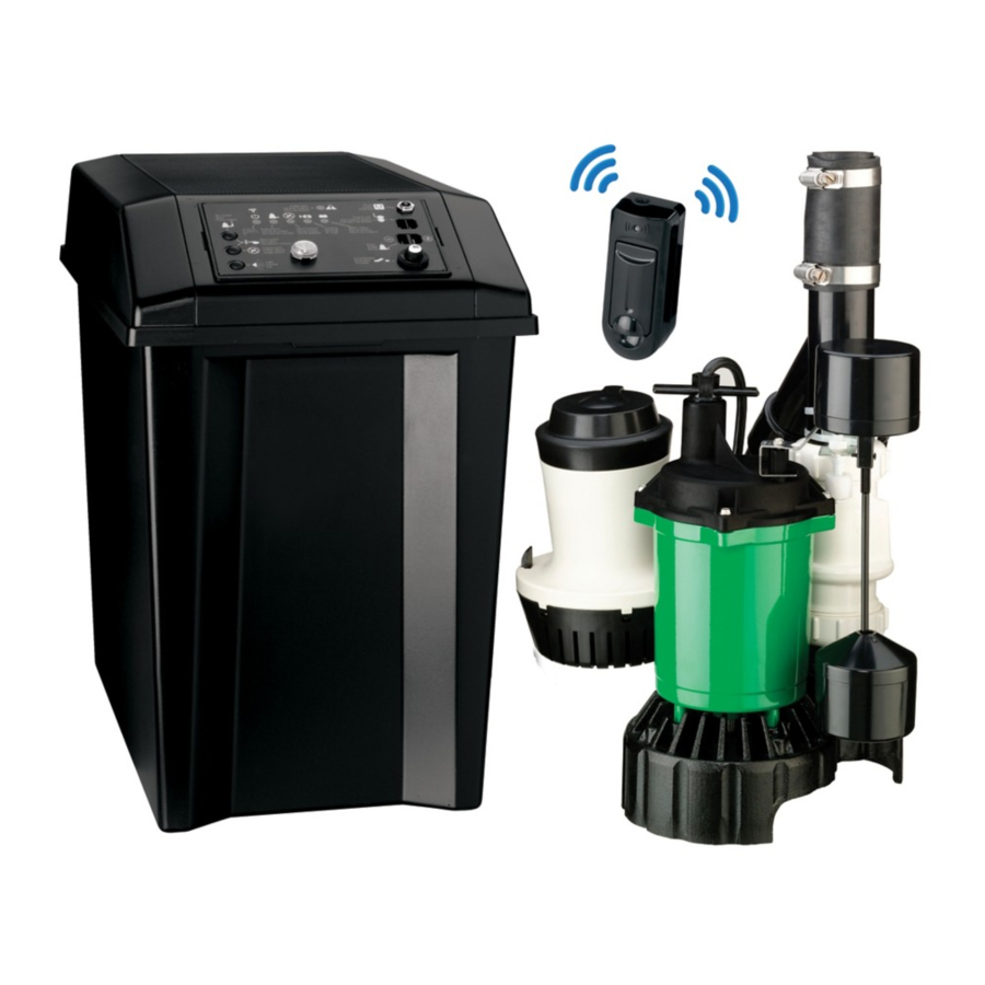
- Page 1 BATTERY BACKUP MBSP-2C ENGLISH: 1-16 FRANCAIS: 17-32 ESPANOL: 33-48 INSTALLATION AND OPERATION MANUAL pentair.com...
-
Page 2: Table Of Contents
TABLE OF CONTENTS Safety Information ....................................3 Specifications ....................................... 4 Pump Installation ....................................5 Installation • Operation ..................................6 BBU Wiring and Setup ................................... 7 Wiring • Setup ....................................... 8 Battery Requirements ................................... 9 LED Display ......................................10 Troubleshooting ....................................12 Repair Parts - Primary Pump ................................13 Repair Parts - Battery Backup Unit ..............................14 Warranty ......................................15... -
Page 3: Safety Information
SAFETY INFORMATION IMPORTANT SAFETY INSTRUCTIONS NOTICE This unit is not designed as a waterfall or fountain This manual contains important instructions that should be followed pump, or for applications involving salt water or brine! Use with during installation, operation, and maintenance of the product. waterfalls, fountains, salt water or brine will void warranty. -
Page 4: Specifications
(7.6) 10.5 SPECIFICATIONS PS17-118 25 sec. (26.7) Maximum vertical pumping distance is 13.35 feet (3.4M) for Model MBSP-2C. REQUIRED BATTERY CAPACITY Power supply required For best results, use the following AGM Storage Batteries: Primary Sump Pump......115V, 60 HZ. Part Amp-Hour Gal/Charge at 10’... -
Page 5: Pump Installation
piggyback switch out of the way of work and water. (10° angle) Measure height of MBSP-2C Combo Kit from base to top of hose clamp assembly. Subtract 1”. Drop the tape measure into the bottom of sump pit and mark the cut line on the discharge pipe (1”... -
Page 6: Installation • Operation
INSTALLATION • OPERATION Once the Combo Kit is firmly seated in the base of the Once all wiring is complete, fill your pit with water and pit, connect the hose and clamp switch to the existing verify that the PSP removes the water and the BBU doesn't discharge pipe and clamp it securely. -
Page 7: Bbu Wiring And Setup
BBU WIRING AND SETUP Connect the positive (+) charger/controller lead wire Depress the ‘System Test’ button; hold it for one second; (red) to the positive (+) battery terminal (red). Connect release. The ‘Pump Status’ LED should stop flashing. the negative (–) charger/controller lead wire (black) to NOTICE: During normal operation, the flashing ‘Pump the negative (–) terminal (black) on the battery. -
Page 8: Wiring • Setup
WIRING • SETUP LED DISPLAY AND CONTROL BUTTONS System Alert Power In Pump Status Charging AC Power Battery Status Float Switch Silenced Audible Alarm System Reset 12VDC 2AMP Pump Battery Charger System Reset Patent Pending Silence Alarm Circuit Breaker Area Light NOTICE: When the unit is first plugged in, or when it first receives power from the battery, the ‘BATTERY STATUS’... -
Page 9: Battery Requirements
BATTERY REQUIREMENTS BATTERY REQUIREMENTS POSSIBLE PROBLEMS AND REMEDIES Hazardous electric current. Can cause severe Wrong Battery Voltage: Reconnect charger to a 12 volt burns and start a fire if the battery terminals are short battery. circuited. Install the battery in the battery case. To prevent Reversed Battery Connections: Check all connections. -
Page 10: Led Display
LED DISPLAY TABLE II – OPERATING CODE DISPLAYS (LEDS LIGHTED CONTINUOUSLY OR FLASHING) LED Operating Code Display System Operating Condition SYSTEM ALERT SILENCED AUDIBLE ALARM POWER -: (J i : 11 SV AC Power is connected Indicates ot: ) :ooo '--.:'"... - Page 11 LED DISPLAY TABLE IV – ERROR CODE DISPLAYS (LEDS FLASHING) Error Condition and Corrective Action LED Error Code Display ;0� NOTICE: When the 'SYSTEM ALERT' LED is flashing, SYSTEM ALERT look for one of the following error conditions. ALARM SILENCED AC POWER BATTERY STATUS ;6�...
-
Page 12: Troubleshooting
TROUBLESHOOTING PRIMARY PUMP TROUBLESHOOTING Symptom Possible Cause(s) Corrective Action Pump is not plugged in. Check and see if pump is plugged into a proper outlet. Blown fuse. If blown, replace with fuse of proper size. If voltage under recommended minimum, check size of wiring from main switch Low line voltage on property. -
Page 13: Repair Parts - Primary Pump
REPAIR PARTS - PRIMARY PUMP Description MS33V10 Power Cord Assembly PS117-54-TSU Vertical Float Switch Assembly FPS17-66 MY1013 (03-30-2021) -
Page 14: Repair Parts - Battery Backup Unit
REPAIR PARTS - BATTERY BACKUP UNIT Key No. Part Description Part Number DC Backup Pump PS17-118* Float Switch PS17-2003 Charger/Controller PS217-1521 Battery Case (Complete) PS17-2044 PS17-2045 AC Adaptor PS17-2008 11” x .14” Plastic Cable Tie Backup Combo Plumbing Kit (with check valve) U137-692 * If pump fails, replace entire system. -
Page 15: Warranty
You specific legal rights and You may also have other rights which vary from state to state. This Limited Warranty is effective January 1, 2021 and replaces all undated warranties and warranties dated before January 1, 2021. PENTAIR MYERS 293 Wright Street, Delavan, WI 53115 Phone: 888-987-8677 • Fax: 800-426-9446 • www.femyers.com In Canada: 490 Pinebush Road, Unit 4, Cambridge, Ontario N1T 0A5 Phone: 800-363-7867 •... - Page 16 Fax: 800-526-3757 Pentair trademarks and logos are owned by Pentair or its affiliates. Third party registered and unregistered trademarks and logos are the property of their respective owners. Because we are continuously improving our products and services, Pentair reserves the right to change specifications without prior notice. Pentair is an equal opportunity employer.
- Page 17 BATTERIE DE SECOURS MBSP-2C GUIDE D’INSTALLATION ET D’UTILISATION pentair.com...
- Page 18 TABLE DES MATIÈRES Consignes de sécurité ..................................19 Spécifications ..................................... 20 Installation de la pompe ..................................21 Installation • Fonctionnement ................................22 Câblage et installation du système de batterie de secours ........................23 Câblage • Installation................................... 24 Exigences relatives à la batterie ................................. 25 Affichage à...
-
Page 19: Consignes De Sécurité
INFORMATION RELATIVE À LA SÉCURITÉ IMPORTANTES CONSIGNES DE SÉCURITÉ Ce manuel contient des consignes importantes qui doivent être suivies REMARQUE : Cet appareil n’est pas conçu pour être utilisé comme pendant l’installation, l’utilisation et l’entretien du produit. pompe de cascade ou de fontaine ou avec de l’eau salée ou de la saumure! L’utilisation avec des cascades, des fontaines, de l’eau salée Ceci est le symbole d’alerte de sécurité. -
Page 20: Spécifications
25 s (26,7) SPÉCIFICATIONS La distance verticale maximale de pompage est de 13,35 pi (3,4 m) pour le CAPACITÉ DE BATTERIE NÉCESSAIRE modèle MBSP-2C. Pour obtenir de meilleurs résultats, utilisez les batteries AGM suivantes : Bloc d’ a limentation requis Gal par recharge Autonomie Pompe de puisard principale.........115 V, 60 Hz Pièce... -
Page 21: Installation De La Pompe
Mesurez la hauteur de la trousse combinée MBSP-2C de la base au sommet de l’ensemble tuyau et collier de serrage. Soustrayez 1 po. Faites tomber le ruban à mesurer au fond du puisard et marquez la ligne de coupe sur le tuyau d’... -
Page 22: Installation • Fonctionnement
INSTALLATION • FONCTIONNEMENT Une fois la trousse combinée fermement installée dans la base Une fois tout le câblage terminé, remplissez la fosse d’eau et de la fosse, raccordez le tuyau et le collier de serrage au tuyau assurez-vous que la pompe de puisard principale évacue l’eau et d’... -
Page 23: Câblage Et Installation Du Système De Batterie De Secours
CÂBLAGE ET INSTALLATION DU SYSTÈME DE SECOURS À BATTERIE Branchez le fil conducteur positif (+) rouge du chargeur/ en sourdine), appuyez à nouveau sur le bouton « Silence Alarm » contrôleur à la borne positive (+) rouge de la batterie. Branchez le (arrêter l’alarme) pendant une seconde. Appuyez sur le bouton fil conducteur négatif (–) noir du chargeur/contrôleur à... -
Page 24: Câblage • Installation
CÂBLAGE • INSTALLATION AFFICHAGE À DEL ET BOUTONS DE COMMANDE System Alert Power In Pump Status Charging AC Power Battery Status Float Switch Silenced Audible Alarm System Reset 12VDC 2AMP Pump Battery Charger System Reset Patent Pending Silence Alarm Circuit Breaker Area Light REMARQUE : Lorsque l’appareil est branché... -
Page 25: Exigences Relatives À La Batterie
EXIGENCES RELATIVES À LA BATTERIE EXIGENCES RELATIVES À LA BATTERIE recharger, essayez de réinitialiser le chargeur une fois ou deux (appuyez Courant électrique dangereux. Peut causer de graves simultanément sur les boutons System Test [tester le système] et brûlures et provoquer un incendie si les bornes de la batterie sont Silence Alarm [arrêter l’alarme] pour réinitialiser le chargeur). -
Page 26: Affichage À Del
AFFICHAGE À DEL TABLEAU II – AFFICHAGE DES CODES DE FONCTIONNEMENT (VOYANTS ALLUMÉS CONTINUELLEMENT OU CLIGNOTANTS) LED Operating Code Display System Operating Condition SYSTEM ALERT SILENCED AUDIBLE ALARM POWER -: (J i : 11 SV AC Power is connected Indicates ot: ) :ooo '--.:'"... - Page 27 AFFICHAGE À DEL TABLEAU IV – AFFICHAGE DE CODES D’ERREUR (VOYANTS CLIGNOTANTS) Types de problèmes et solutions Error Condition and Corrective Action Affichage à DEL des codes d’erreur LED Error Code Display ;0� REMARQUE : NOTICE: ALERTE DU SYSTÈME When the 'SYSTEM ALERT' LED is flashing, SYSTEM ALERT Lorsque le voyant « SYSTEM ALERT »...
-
Page 28: Dépannage
DÉPANNAGE POMPE PRINCIPALE – DÉPANNAGE Symptôme Cause(s) possible(s) Mesure corrective La pompe n’est pas branchée. Vérifiez si la pompe est branchée à une prise appropriée. Fusible brûlé. Remplacez le fusible par un fusible de calibre approprié s’il est brûlé. Si la tension est inférieure au minimum recommandé, vérifiez la taille du câblage du Tension de ligne basse commutateur principal de la propriété. -
Page 29: Pièces De Rechange - Pompe Principale
PIÈCES DE RECHANGE – POMPE PRINCIPALE Réf. Description Qté MS33V10 Assemblage du cordon d’alimentation PS117-54-TSU Assemblage de l’interrupteur à flotteur FPS17-66 vertical MY1013 (03-30-2021) -
Page 30: Pièces De Rechange - Appareil De Secours À Batterie
PIÈCES DE RECHANGE – UNITÉS DE BATTERIE DE SECOURS Légende Description de la pièce Numéro de pièce Pompe de secours à courant continu (CC) PS17-118* Interrupteur à flotteur PS17-2003 Chargeur/contrôleur PS217-1521 Boîtier de batterie (complet) PS17-2044 PS17-2045 Adaptateur CA PS17-2008 Attache de câble en plastique 11 po x 0,14 po Trousse de plomberie de secours (avec clapet de non-retour) U137-692... -
Page 31: Garantie
État à l’autre. La présente garantie limitée entre en vigueur le 1er janvier 2021 et remplace toutes les garanties non datées ainsi que celles antérieures à cette date. PENTAIR MYERS 293 Wright Street, Delavan, WI 53115 Téléphone : 888 987-8677 • Télécopieur : 800 426-9446 • www.femyers.com Au Canada : 490 Pinebush Road, Unit 4, Cambridge, Ontario N1T 0A5... - Page 32 Télécopieur : 1 800 526-3757 Toutes les marques de commerce et tous les logos de Pentair appartiennent à Pentair ou ses filiales. Les marques de commerce et logos de tiers déposés et non déposés sont la propriété de leurs propriétaires respectifs. Dans la mesure où Pentair améliore constamment ses produits et services, la société se réserve le droit d’en modifier les spécifications sans préavis. Pentair est un employeur offrant l’égalité professionnelle.
- Page 33 BATERÍA AUXILIAR MBSP-2C MANUAL DE INSTALACIÓN Y FUNCIONAMIENTO pentair.com...
- Page 34 ÍNDICE Información de seguridad ................................... 35 Especificaciones ....................................36 Instalación de la bomba ..................................37 Instalación • Funcionamiento ................................38 Configuración y cableado de BBU................................ 39 Cableado • Configuración ..................................40 Requisitos de la batería ..................................41 Pantalla LED ....................................... 42 Resolución de problemas ..................................44 Partes de repuesto - Bomba principal ..............................
-
Page 35: Información De Seguridad
INFORMACIÓN DE SEGURIDAD INSTRUCCIONES IMPORTANTES DE SEGURIDAD AVISO ¡Esta unidad no está diseñada como una bomba para cascada o Este manual contiene instrucciones importantes que se deben seguir durante fuente, ni para aplicaciones con agua salada o salmuera! Si la usa para la instalación, el funcionamiento y el mantenimiento del producto. -
Page 36: Especificaciones
ESPECIFICACIONES (26.7) La distancia máxima de bombeo vertical es 13.35 pies (3.4 m) para el modelo MBSP-2C. CAPACIDAD QUE SE REQUIERE PARA LA BATERÍA Fuente de alimentación que se requiere Para obtener los mejores resultados, use las siguientes baterías de Bomba de sumidero principal........115 V, 60 HZ. -
Page 37: Instalación De La Bomba
(ángulo de 10°) de trabajo y del agua. Mida la altura del Kit combinado MBSP-2C desde la base hasta la parte superior del ensamblaje de la abrazadera de la manguera. Restar 1”. -
Page 38: Instalación • Funcionamiento
INSTALACIÓN • FUNCIONAMIENTO Una vez que el Kit combinado esté firmemente asentado en la base Una vez que se complete todo el cableado, llene el pozo con agua y del pozo, conecte el interruptor de la abrazadera y la manguera al verifique que la PSP elimine el agua y que la BBU no funcione. -
Page 39: Configuración Y Cableado De Bbu
CONFIGURACIÓN Y CABLEADO DE BBU Conecte el cable conductor positivo (+) del cargador/controlador (alarma audible apagada), presione nuevamente el botón “Silence (rojo) en el terminal positivo (+) de la batería (rojo). Conecte el Alarm” (apagar alarma) por un segundo. Suelte el botón “System cable conductor negativo (-) del cargador/controlador (negro) en Test”... -
Page 40: Cableado • Configuración
CABLEADO • CONFIGURACIÓN PANTALLA LED Y BOTONES DE CONTROL System Alert Power In Pump Status Charging AC Power Battery Status Float Switch Silenced Audible Alarm System Reset 12VDC 2AMP Pump Battery Charger System Reset Patent Pending Silence Alarm Circuit Breaker Area Light AVISO: Cuando la unidad se enchufa por primera vez, o cuando recibe alimentación por primera vez de la batería, la luz LED de “BATTERY STATUS”... -
Page 41: Requisitos De La Batería
REQUISITOS DE LA BATERÍA REQUISITOS DE LA BATERÍA POSIBLES PROBLEMAS Y SOLUCIONES Corriente eléctrica peligrosa. Puede causar Voltaje de la batería incorrecto: Reconectar el cargador a una quemaduras graves e iniciar incendios si los terminales de la batería batería de 12 voltios. están en cortocircuito. -
Page 42: Pantalla Led
PANTALLA LED TABLA II – PANTALLAS DE CÓDIGO OPERATIVO (LUCES LED ENCENDIDAS CONTINUAMENTE O PARPADEANTES) LED Operating Code Display System Operating Condition Pantalla de código operativo de LED Condición operativa del sistema ALERTA DEL SISTEMA SYSTEM ALERT ALARMA AUDIBLE APAGADA SILENCED AUDIBLE ALARM ESTADO DE LA BOMBA CARGANDO... - Page 43 PANTALLA LED TABLA IV -PANTALLAS DE CÓDIGO DE ERROR (LUCES LED PARPADEANTES) Condiciones de errores y acciones correctivas Error Condition and Corrective Action Pantalla de código de error de LED LED Error Code Display ;0� AVISO: NOTICE: ALERTA DEL SISTEMA When the 'SYSTEM ALERT' LED is flashing, SYSTEM ALERT Cuando la luz LED de “SYSTEM ALERT”...
-
Page 44: Resolución De Problemas
RESOLUCIÓN DE PROBLEMAS RESOLUCIÓN DE PROBLEMAS DE LA BOMBA PRINCIPAL Síntoma Causas posibles Medida correctiva La bomba no está enchufada. Revise si la bomba está enchufada en un tomacorriente apropiado. Fusible quemado. Si está quemado, reemplácelo por un fusible del tamaño adecuado. Si el voltaje es menor que el mínimo recomendado, revise el tamaño del cableado desde Voltaje de línea bajo el interruptor principal en la propiedad. -
Page 45: Partes De Repuesto - Bomba Principal
PARTES DE REPUESTO - BOMBA PRINCIPAL Ref. Descripción Cantidad MS33V10 Ensamblaje de cable de alimentación PS117-54-TSU Ensamblaje del interruptor flotante FPS17-66 vertical MY1013 (03-30-2021) -
Page 46: Partes De Repuesto - Unidad De Batería Auxiliar
PARTES DE REPUESTO - UNIDAD DE BATERÍA AUXILIAR N.° de referencia Descripción de la parte Número de parte Bomba auxiliar de CC PS17-118* Interruptor flotante PS17-2003 Cargador/controlador PS217-1521 Caja de batería (completa) PS17-2044 PS17-2045 Adaptador de CA PS17-2008 Sujetacables de plástico de 11” x .14” Kit de tubería combinado auxiliar (con válvula de retención) U137-692 * Si la bomba presenta fallas, reemplace todo el sistema. -
Page 47: Garantía
Esta Garantía limitada tiene vigencia a partir del 1 de enero de 2021 y reemplaza a todas las garantías sin fecha y las garantías con fechas anteriores al 1 de enero de 2021. PENTAIR MYERS 293 Wright Street, Delavan, WI 53115 Teléfono: 888-987-8677 •... - Page 48 Fax: 800-526-3757 Las marcas comerciales y logos de Pentair son propiedad de Pentair o de sus filiales. Las marcas comerciales y logos registrados y no registrados de terceros son propiedad de sus respectivos titulares. Debido a que mejoramos continuamente nuestros productos y servicios, Pentair se reserva el derecho de modificar las especificaciones sin previo aviso. Pentair es un empleador que ofrece igualdad de oportunidades.