Table of Contents
Advertisement
Quick Links
Advertisement
Table of Contents

Related Manuals for Fluke FEV100


Summary of Contents for Fluke FEV100
- Page 1 FEV100 Electrical Vehicle Charging Station Test Adapter Users Manual PN 5278136, April 2021 © 2021 Fluke Corporation. All rights reserved. Specifications are subject to change without notice. All product names are trademarks of their respective companies.
-
Page 2: Contact Fluke
Table 1. Symbols Introduction The FEV100 (the Product) tests the function and safety of AC charging stations Level 2 (208 V AC or 240 V AC) and Level 1 (120 V AC). With this adapter, charging stations are tested in accordance with SAE J1772. -
Page 3: Safety Information
Safety Information A Warning identifies conditions and procedures that are dangerous to the user. A Caution identifies conditions and procedures that can cause damage to the Product or the equipment under test. WX Warning To prevent the possibility of electric shock or personal injury: •... -
Page 4: Transport And Storage
Measurements on live conductors (L1, L2/N) and on PE ground conductor • Test of Control Pilot CP signal Kit Components The FLK-FEV100/TY1 Kit contains the following items: FLK-FEV100/BASIC Test Adapter FLK-FEV-COM/TY1 Type 1 Connector & Cable Soft Carrying Case Users Manual... -
Page 5: Operation Elements And Connectors
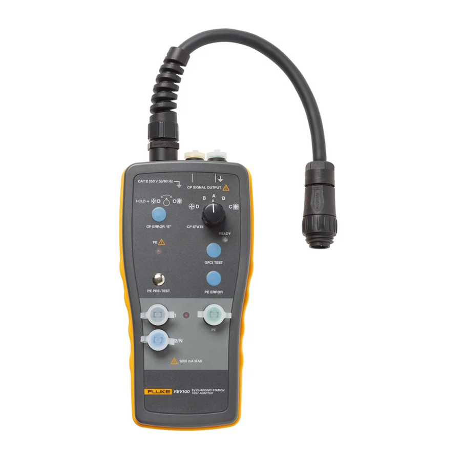
Description of Warning Marks on Front Panel Terminals with low voltage output (approx. ±12 V) powered by the charging station. Terminal marked with is connected to PE. Use for test purposes only. The CP Signal Output terminals can be hazardous if there is a charging station error or incorrect wiring. - Page 6 Figure 3. Top of the Product Test cable input CP Signal output terminal (yellow) CP Signal output terminal (connected to PE) (green) Figure 4. Back of the Product Testing Charging Stations WX Warning To prevent possible electric shock, fire, or personal injury: •...
- Page 7 Additional advanced tests such as Insulation Resistance, Power Quality, Analysis of the Control Pilot waveform, and Loop Impedance can also be done using the adapter in conjunction with appropriate test and measurement equipment. The adapter is compatible with Fluke and Amprobe test and measurement instrumentation. Grounding protection Pre-Test The Grounding J Pre-Test safety feature allows the operator to test the PE conductor for possible presence of dangerous voltage against earth.
- Page 8 Initiating a charging cycle: 1. Connect the adapter cable to the charging station. 2. Turn a CP switch to B position and wait 3 to 5 seconds – in commercial stations this may initiate a station to ask for payment information 3.
- Page 9 9.5 % ≤ Duty Cycle < 10 %, Maximum current = 6 A 10 % ≤ Duty Cycle ≤ 80 %, Maximum current = (duty cycle %) x 0.6 85 % < Duty Cycle ≤ 96 %, Maximum current = (duty cycle % - 64) x 2.5 96 % <...
- Page 10 CP Error “E” simulation The standard SAE J1772 defines Error “E” as a state when charging station is: disconnected from vehicle, disconnected from utility, there is a loss of utility power or control pilot is short to control pilot reference (ground). To simulate the CP Error “E”: 1.
-
Page 11: Maintenance
Maintenance When using the test adapter in compliance with the Users Manual, no special maintenance is required. However, should functional errors occur during normal operation, after sales service will repair your instrument. Please contact the local service office. Cleaning WX Warning •... -
Page 12: Specifications
Specifications General Features Input voltage ......... U = 120 V, U = 120 V, U = 208 V, L1/N L2/N L1/L2 60 Hz (three-phase system) or = 120 V, U = 120 V, U = 240 L1/N L2/N L1/L2 V, 60 Hz (single-phase system), ±10% voltage fluctuations from nominal EV connector (EVC-13) .... - Page 13 LIMITED WARRANTY AND LIMITATION OF LIABILITY Each Fluke product is warranted to be free from defects in material and workmanship under normal use and service. The warranty period is three years and begins on the date of shipment. Parts, product repairs, and services are warranted for 90 days.