Table of Contents
Advertisement
Quick Links
Advertisement
Table of Contents

Related Manuals for Hoshizaki RM-49


Summary of Contents for Hoshizaki RM-49
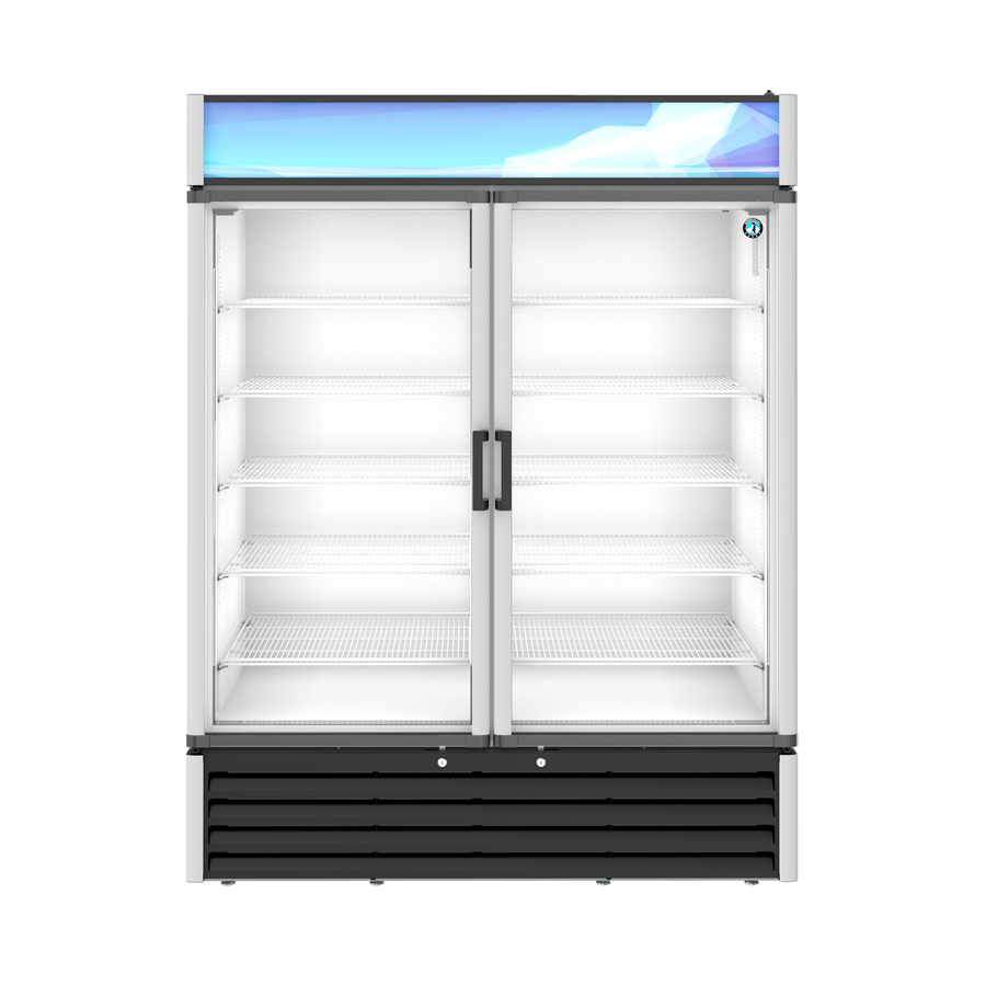
- Page 1 SERVICE MANUAL FOR MODEL RM-49...
- Page 2 REQUIRED TOOLS RATCHET WITH SOCKET OF OPEN WRENCH OF 1/2” CORDLESS DRILL DRIVE CUTTING TUBING 7/16” SCREWDRIVER SET WITH VISE GRIP WATCHER SLOTTED PIERCING VALVE SOCKET OF 9/32” SCREWDRIVER...
- Page 3 REQUIRED EQUIPMENT OXIACETILENE DRY NITROGEN VACUUM PUMP WITH EQUIPMENT EQUIPMENT MICRON GAUGE MANIFOLD PRESSURE REFRIGERANT RECOVERY LEAK DETECTOR GAUGES MACHINE...
-
Page 4: Table Of Contents
CONTENTS • Instructions to replace LED Power Supply. •Instructions to replace high intensity LED flexible strips. • Instructions to replace interior LED strips lights. • Instructions to replace condenser fan motor. • Instructions to replace evaporator fan motor. • Instructions to replace electronic thermostat. •... -
Page 5: Instructions To Replace Led Power Supply
DISCONNECT UNIT FROM POWER SUPPLY BEFORE DOING ANY SERVICE Instructions to Replace LED Power Supply. 1. Unscrew the two screws that hold 3. Grab the acrylic sign and pull it out. in place the top of the header sign , 2. - Page 6 DISCONNECT UNIT FROM POWER SUPPLY BEFORE DOING ANY SERVICE Instructions to Replace LED Power Supply. 4. In order to remove the Power 5. Disconnect the Power Supply’s electrical Supply, unscrew the two screws that 6. To install the new Power Supply connector.
-
Page 7: Instructions To Replace High Intensity Led Flexible Strips
DISCONNECT UNIT FROM POWER SUPPLY BEFORE DOING ANY SERVICE Instructions to Replace High Intensity LED Flexible Strips . 1. Unscrew the two screws that hold in 3. Grab the acrylic sign and pull it place the top of the header sign , 2. - Page 8 DISCONNECT UNIT FROM POWER SUPPLY BEFORE DOING ANY SERVICE Instructions to Replace High Intensity LED Flexible Strips . 5. Remove the high intensity LED flexible 6. To install the new high 4. Disconnect the electrical connector strip by pulling it out from its base. intensity LED flexible strip, of LED strip Light.
- Page 9 DISCONNECT UNIT FROM POWER SUPPLY BEFORE DOING ANY SERVICE Instructions to Replace LED Strips . LED cover profile 1. Remove the LED profile 2. Disconnect the electrical 4. To install the new LED strip 3. Use a slotted screwdriver cover of breaker strip using connector of LED strip reverse the previous steps.
-
Page 10: Instructions To Replace Condenser Fan Motor
DISCONNECT UNIT FROM POWER SUPPLY BEFORE DOING ANY SERVICE Instructions to Replace Condenser Fan Motor 4. Remove the two bolts that hold in place the 1. Unscrew the four screws 3. Disconnect the Tyco rails using a 1/2” open that hold in place the 2. - Page 11 DISCONNECT UNIT FROM POWER SUPPLY BEFORE DOING ANY SERVICE Instructions to Replace Condenser Fan Motor 5. Remove the two screws that holds in place the evaporation pan bracket to 7. The condensing unit can be 6. Pull out the condensing unit from the cabinet base using a 1/4”...
- Page 12 DISCONNECT UNIT FROM POWER SUPPLY BEFORE DOING ANY SERVICE Instructions to Replace Condenser Fan Motor 8. Disconnect the Tyco electrical 9. Unscrew the two screws that hold in connector of the condenser fan 10. Pull out the condenser fan. place the base motor to the rails using motor.
- Page 13 DISCONNECT UNIT FROM POWER SUPPLY BEFORE DOING ANY SERVICE Instructions to Replace Condenser Fan Motor 11. Remove the bolt that hold in 12. Unscrew. the two screws that 13. To install the new condenser place the fan blade to the fan hold in place the base motor to fan motor reverse the previous motor using a 9/32”...
-
Page 14: Instructions To Replace Evaporator Fan Motor
DISCONNECT UNIT FROM POWER SUPPLY BEFORE DOING ANY SERVICE Instructions to Replace the Evaporator Fan Motor. Fan Guard 3. Unscrew the four screws that hold in 1. Unscrew the four screws that hold in 2. Remove the bolt that hold in place the place the support base motor to the place the fan guard on the air baffle fan blade to the fan motor using a 9/32”... - Page 15 DISCONNECT UNIT FROM POWER SUPPLY BEFORE DOING ANY SERVICE Instructions to Replace the Evaporator Fan Motor. 5. Unscrew the three screws that hold in 4. Disconnect the Tyco electrical 6. To install the new evaporator fan place the support base motor to the fan connector of the evaporator fan motor reverse the previous steps.
-
Page 16: Instructions To Replace Electronic Thermostat
DISCONNECT UNIT FROM POWER SUPPLY BEFORE DOING ANY SERVICE Instructions to Replace The Electronic Thermostat. 2. Turn 90° both screws to loosen their cams and the 1. Remove the front 3. Disconnect the 4. To install the new front panel will detach . frame of the connectors located in electronic thermostat... -
Page 17: Instructions To Replace Thermostat Ambient Sensor
DISCONNECT UNIT FROM POWER SUPPLY BEFORE DOING ANY SERVICE Instructions to replace Ambient Sensor. 2. Turn 90° both screws to 3. Disconnect the 4. Unscrew the two screws 1. Remove the front loosen their cams and the connector of the that hold the wires in frame of the front panel will detach . - Page 18 DISCONNECT UNIT FROM POWER SUPPLY BEFORE DOING ANY SERVICE Instructions to replace Ambient Sensor. Fan Guard 5. Unscrew the four screws that hold in 6. Remove the bolt that hold in place 7. Pull out the ambient sensor from its place the fan guard on the air baffle the fan blade to the fan motor plastic clip support.
- Page 19 DISCONNECT UNIT FROM POWER SUPPLY BEFORE DOING ANY SERVICE Instructions to replace Ambient Sensor. 8. Use masking tape to splice the damaged 9. Pull both ambient sensors through the cut ambient sensor with the new. This out of display . Once the splice is visible, operation will serve as guide to remove the remove the tape and damage sensor and damage sensor and connect the new to the...
-
Page 20: Instructions To Replace Starting Relay, Overload Protector And Starting Capacitor
DISCONNECT UNIT FROM POWER SUPPLY BEFORE DOING ANY SERVICE Instruction to Replace Starting Relay, Overload Protector and Starting Capacitor. 4. Remove the two bolts that hold in place the 1. Unscrew the four screws 3. Disconnect the Tyco rails using a 1/2” open that hold in place the 2. - Page 21 DISCONNECT UNIT FROM POWER SUPPLY BEFORE DOING ANY SERVICE Instruction to Replace Starting Relay, Overload Protector and Starting Capacitor. 5. Remove the two screws that holds in place the evaporation pan 7. The condensing unit can be bracket to the cabinet base using a 6.
- Page 22 DISCONNECT UNIT FROM POWER SUPPLY BEFORE DOING ANY SERVICE Instruction to Replace Starting Relay, Overload Protector and Starting Capacitor. 8. Remove the two bolts that hold in place the electrical box 9. Remove the electrical box cover by pulling it out. cover using a ¼”...
- Page 23 DISCONNECT UNIT FROM POWER SUPPLY BEFORE DOING ANY SERVICE Instruction to Replace Starting Relay, Overload Protector and Starting Capacitor. LOCATION OF ELECTRICAL CONNECTIONS Relay Starting capacitor wires Start Relay wire connections connections Overload protector Ground wire . Overload protector wires connection Starting Capacitor...
- Page 24 DISCONNECT UNIT FROM POWER SUPPLY BEFORE DOING ANY SERVICE Instruction to Replace Starting Relay, Overload Protector and Starting Capacitor. 11. Use a slotted screwdriver as a pry bar 10. Remove the screws that hold in place to pull out the electrical connectors 12.
- Page 25 DISCONNECT UNIT FROM POWER SUPPLY BEFORE DOING ANY SERVICE Instruction to Replace Starting Relay, Overload Protector and Starting Capacitor. 14. Insert a flat screwdriver in 15. To remove the overload 13. Remove the four bolts that the slot of the plastic protector use a slotted 16.
- Page 26 DISCONNECT UNIT FROM POWER SUPPLY BEFORE DOING ANY SERVICE Instruction to Replace Starting Relay, Overload Protector and Starting Capacitor. 18. Use a slotted screwdriver as a pry bar to disconnect the 17. Use a slotted screwdriver as a pry bar to remove the terminals of the starting capacitor.
-
Page 27: Instructions To Replace Compressor
DISCONNECT UNIT FROM POWER SUPPLY BEFORE DOING ANY SERVICE Instructions to Replace Compressor. 4. Remove the two bolts that hold in place the 1. Unscrew the four screws 3. Disconnect the Tyco rails using a 1/2” open that hold in place the 2. - Page 28 DISCONNECT UNIT FROM POWER SUPPLY BEFORE DOING ANY SERVICE Instructions to Replace Compressor. 5. Remove the two screws that holds in place the evaporation pan bracket to the cabinet base using a 7. The condensing unit can be 6. Pull out the condensing unit from 1/4”...
- Page 29 DISCONNECT UNIT FROM POWER SUPPLY BEFORE DOING ANY SERVICE Instructions to Replace Compressor. 8. Remove the two bolts that hold in place the electrical box 9. Remove the electrical box cover by pulling it out. cover using a ¼” socket screwdriver.
- Page 30 DISCONNECT UNIT FROM POWER SUPPLY BEFORE DOING ANY SERVICE Instructions to Replace Compressor. 10 . The first step is to recover all 13. To remove the filter refrigerant from the system by 11. Open Manifold Gauge 12. Warm the brazing of dryer, slowly warm up installing a piercing valve in the Pressure valves and...
- Page 31 DISCONNECT UNIT FROM POWER SUPPLY BEFORE DOING ANY SERVICE Instructions to Replace Compressor. 16. Not all compressor removal 14. Remove the four nuts requires cleaning the low and high 17. Place the new 15. Remove the that hold in place the sides of the system.
- Page 32 DISCONNECT UNIT FROM POWER SUPPLY BEFORE DOING ANY SERVICE Instructions to Replace Compressor. 20. Braze the filter to the condenser 21. Please review the discharge line and to the capillary 18. Install the four nuts slides 22 through 26 to tubing.
- Page 33 DISCONNECT UNIT FROM POWER SUPPLY BEFORE DOING ANY SERVICE Instructions to Replace Compressor. 22. Use the Piercing Valve already 23. Turn on the vacuum pump to start evacuating the system. This should take up to 20 installed in the service tube of minutes for the micron gauge to reach 200 microns or less.
- Page 34 DISCONNECT UNIT FROM POWER SUPPLY BEFORE DOING ANY SERVICE Instructions to Replace Compressor. 25. Unplug the cooler. Pinch the service tubes using a vise 24. After the vacuum process has been finished, close the pinch and proceed to remove the manifold gauges and valves of the manifold gauges and proceed to connect the piercing valve.
-
Page 35: Instructions To Replace Door
DISCONNECT UNIT FROM POWER SUPPLY BEFORE DOING ANY SERVICE Instructions to Replace the Door. 3. Use a cordless drill drive with a 1. Unscrew the four screws that Phillips bit # 3 to remove the three hold in place the front grill , using 2. - Page 36 DISCONNECT UNIT FROM POWER SUPPLY BEFORE DOING ANY SERVICE Instructions for Replacing the Door. 4. To remove the door, pull it 5. To install the new door reverse the downward from the upper hinge. previous steps..