Blodgett SB-10SC Installation Operation & Maintenance
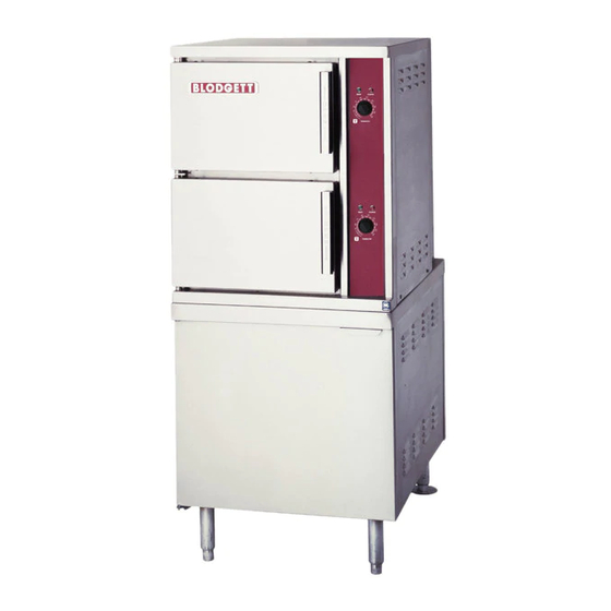
Convection steamer on a steam coil boiler base
Hide thumbs
Also See for SB-10SC:
- Brochure & specs (12 pages) ,
- Parts list (9 pages) ,
- Specifications (2 pages)
Table of Contents
Advertisement
Advertisement
Table of Contents

Related Manuals for Blodgett SB-10SC


Summary of Contents for Blodgett SB-10SC
- Page 1 SB-6SC, SB-10SC and SB-16SC CONVECTION STEAMER ON A STEAM COIL BOILER BASE INSTALLATION – OPERATION – MAINTENANCE BLODGETT OVEN COMPANY www.blodgett.com 44 Lakeside Avenue, Burlington, Vermont 05401 USA Telephone (800) 331-5842, (802) 860-3700 Fax: (802) 864-0183 S00060 Rev B (12/04)
-
Page 2: Important Notes
IMPORTANT NOTES FOR INSTALLATION AND OPERATION It is recommended that this manual be read thoroughly and that all instructions be followed carefully. This is the safety alert symbol. It is used to alert you to potential personal injury hazards. Obey all safety messages that follow this symbol to avoid possible injury or death. -
Page 3: Table Of Contents
TABLE OF CONTENTS DESCRIPTION PAGE Important Notes...2 Service Connections ...4 Introduction ...5 1.0 Installation Instructions...6 2.0 Information to Steam Fitter...8 3.0 Operating Instructions ...10 4.0 Periodic Maintenance...12 5.0 Cleaning Instructions...14 6.0 Troubleshooting ...16... -
Page 4: Service Connections
Less than 60 PPM Less than 20 PPM Less than 13 PPM Less than 1.5 PPM 7.0-8.5 24 [610] 2 [51] 2.75 [70] 0 [0] 3.5 [89] 2.5 [64] 1.5 [38] 10 [254] 10 [254] SB-6SC & SB-10SC TOP VIEW SB-16SC TOP VIEW... -
Page 5: Introduction
ASME Code and approved as a steam boiler restricted to operation at pressure not to exceed 15 psi. SB-6SC steamer has a pan capacity of 6 (2-1/2") pans. SB-10SC has a pan capacity of 10 (2-1/2") pans. SB-16SC has a pan capacity of 16 (2- 1/2") pans. -
Page 6: Installation Instructions
1.0 INSTALLATION INSTRUCTIONS UNPACKING Immediately after unpacking, check for possible shipping damage. If the appliance is found to be damaged, save the packaging material and contact the carrier within 15 days of delivery. Before installing, verify the electrical rating agrees with the specification on the rating plate. - Page 7 1.0 INSTALLATION INSTRUCTIONS (continued) Ideally an exhaust system should be located directly above the appliance to exhaust steam and heat generated by the appliance. 1. Set the unit in place and level using a spirit level. 2. Ascertain that a floor drain (open gap) is convenient to the appliance drain. 3.
-
Page 8: Information To Steam Fitter
2.0 INFORMATION TO STEAM FITTER Assuming availability of 30 psi supply steam pressure immediately to the appliance, then pipe sizes of ½" or 3/4" or 1" will deliver respectively 90, 165 or 385 lbs. of steam per hour to the appliance Heat Exchanger. From the foregoing to use ½" pipe line would most likely prove inadequate. - Page 9 It is suggested that, wherever possible, the steam supply line to the appliance is a separate line from the steam source. If the appliance must be supplied from a line supplying other appliances, the pipe sizes and pressure will have to be verified. Further, during idle periods, when the steam in the supply line is not in use, water will form from condensed steam in the supply line.
-
Page 10: Operating Instructions
3.0 OPERATING INSTRUCTIONS START UP INSTRUCTIONS Turn on water and steam supply to appliance. Open cabinet door and turn on Power Switch. Pilot light will come ON and steam generating will begin. In approximately 20 minutes, sufficient amount of pressurized steam will have been generated in the heat exchanger. - Page 11 3.0 OPERATING INSTRUCTIONS (Continued) CAUTION: An obstructed drain can cause personal injury or property damage. Frequently check that the compartment drain and plumbing is free of all obstructions. Never place food containers, food or food portion bags in the cooking compartment in such a way that the compartment drain becomes obstructed.
-
Page 12: Periodic Maintenance
4.0 PERIODIC MAINTENANCE CAUTION: Protect yourself. When flushing control, hot water and steam will flow out of the drain. Be sure to flush your boiler water level control daily. Failure to follow this procedure can cause the control to malfunction resulting in serious boiler damage. The Boiler Water Level Control installed on your boiler requires periodic maintenance. - Page 13 Continue draining water for about fifteen (15) seconds, from control until water is clean. Manually close valve. Recheck gauge glass. If water level has dropped significantly, wait for the boiler to restore water level and pressure and repeat if necessary. 1.
-
Page 14: Cleaning Instructions
5.0 CLEANING INSTRUCTIONS Never spray water into electric controls. CAUTION: Do not use cleaning agents that are corrosive. CAUTION: Live steam and accumulated hot water in the compartment may be released when the door is opened. 1. Keep exposed cleanable areas of unit clean at all times. 2. - Page 15 5.0 CLEANING INSTRUCTIONS (Continued) DESCALING BOILER CAUTION: Improper use of this procedure may damage your appliance! 1. With Generator tank empty, close manual blowdown valve. If appliance is equipped with Automatic Blowdown, turn water supply OFF to appliance. Turn power switch ON, this will energize and close blowdown valve. 2.
-
Page 16: Troubleshooting
6.0 TROUBLESHOOTING NOTICE: Contact the factory, the factory representative or local service company to perform maintenance and repairs. Refer to warranty terms. DOOR LEAKS 1. Check for damage to door gasket. WATER ACCUMULATES IN THE COMPARTMENT 1. Compartment drain screen clogged. Remove and clean thoroughly and then replace. - Page 17 TO CALIBRATE PRESSURE SWITCHES NOTE: Pressure switches are factory set. Calibration is only required if pressure switches are replaced or if adjustment is required. Pressure switch range is from 1 to 15 psi. Adjust all settings to maximum on high signal adjustment screw on pressure switches. Adjust in the following sequence: - High limit pressure switch.