Blodgett KLS-100G Installation Operation & Maintenance
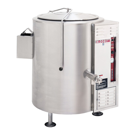
Gas fired tri-leg stationary kettle
Hide thumbs
Also See for KLS-100G:
- Parts list (11 pages) ,
- Brochure & specs (12 pages) ,
- Installation operation & maintenance (12 pages)
Advertisement
Quick Links
Advertisement

Related Manuals for Blodgett KLS-100G


Summary of Contents for Blodgett KLS-100G
- Page 1 KLS-80G and KLS-100G GAS FIRED TRI-LEG STATIONARY KETTLE INSTALLATION – OPERATION – MAINTENANCE BLODGETT OVEN COMPANY www.blodgett.com 44 Lakeside Avenue, Burlington, Vermont 05401 USA Telephone (800) 331-5842, (802) 860-3700 Fax: (802) 864-0183 S00072 Rev C (12/07)
- Page 2 IMPORTANT NOTES FOR INSTALLATION AND OPERATION It is recommended that this manual be read thoroughly and that all instructions be followed carefully. This is the safety alert symbol. It is used to alert you to potential personal injury hazards. Obey all safety messages that follow this symbol to avoid possible injury or death.
-
Page 3: Table Of Contents
TABLE OF CONTENTS DESCRIPTION PAGE 1.0 Service Connections...4 2.0 Installation ...5 3.0 Operation...11 4.0 Cleaning Instructions ...16 5.0 Maintenance ...20 6.0 Service ...21 7.0 Troubleshooting ...25 Appendix A, Material Safety Data Sheet ...26... -
Page 4: Service Connections
Unless otherwise specified, Field Wire Electrical Connection to be 120 Volts, 60 Hertz single phase with grounding wire. Unit furnished with 6' cord and 3 prong plug. Total max. amps 2.0. MODEL SUPPLY PRESSURES (W.C.) Natural KLS-80G KLS-100G 6"-14"(152-355mm) OPEN 6.88 [175] CLOSED 5 [128] 2" VALVE) 23 1/2 [598]... -
Page 5: Installation
The electrical diagram is located on the inside of the console control cover. EXHAUST FANS AND CANOPIES: Canopies are set over ranges, ovens and kettles for ventilation purposes. It is recommended that a canopy extend 6" past appliance and be located 7.5 feet from the floor. - Page 6 All units must be installed in such a manner that the flow of combustion and ventilation air are not obstructed. Provisions for an adequate air supply must also be provided. Do not obstruct the lower front or right side of the unit, as combustion air enters through these areas. The bottom of the control area must also remain obstructed.
- Page 7 2.0 INSTALLATION (Continued) The serial plate on the lower right side of the unit indicates the type of gas your unit is equipped to burn. Do NOT connect to any other gas type. A ¾" NPT line is provided at the rear for the connection. Each unit is equipped with an internal pressure regulator which is set for 4"...
- Page 8 2.0 INSTALLATION (Continued) WARNING: If this appliance is equipped with casters, the installation shall be made with a connector that complies with the standard for connectors for moveable gas appliances, ANSI Z21.69-CSA 6.16 and a quick-disconnect device that complies with the standard for quick- disconnect devices for use with gas fuel, ANSI Z21.41-CSA 6.9;...
- Page 9 2.0 INSTALLATION (Continued) ELECTRICAL CONNECTION WARNING: Do not connect the kettle to the electrical supply until after the gas connection has been made. 1. 120 VAC - 60 Hz - Single Phase WARNING: ELECTRICAL GROUNDING INSTRUCTIONS This appliance is equipped with a three-prong (grounding) plug for your protection against shock hazard and should be plugged directly into a properly grounded three-prong receptacle.
- Page 10 2.0 INSTALLATION (Continued) PERFORMANCE CHECK The following items should be checked before or within the first 30 days of operation by a qualified service technician. 1. Verify correct gas type against rating plate on unit. 2. Verify correct voltage, cycle and phase against rating plate on unit. 3.
-
Page 11: Operation
3.0 OPERATION CAUTION: If you smell gas during the lighting procedure, immediately shut off the gas supply until the leak has been corrected. WARNING: In the event of main burner ignition failure, a 5 minute purge period must be observed prior to re-establishing ignition source. - Page 12 3.0 OPERATION (Continued) At this time the spark igniter will begin sparking at the burner. If after 4 seconds the burner does not light, the control will attempt to relight the burner two additional times at an interval of about 20 seconds.
- Page 13 This light is on whenever the main burner flames are on. 3. (Amber) Low Water Light All kettles are supplied with sufficient distilled water in the pressurized jacket. If at any time the water level falls below that required for proper operation, the kettle will not heat and this light will come on.
- Page 14 3.0 OPERATION (Continued) DAILY OPERATION Daily operation should consist of turning on the power switch and setting thermostat for the desired temperature. The thermostat will cycle the burners on and off to maintain desired temperature. It is recommended the kettle be preheated prior to use. Milk or egg based products should be placed in the kettle before heating however, to prevent sticking.
- Page 15 adhering to the sides. When preparing milk-based products do not preheat the kettle. When planning actual cooking capacity, allow room at top for stirring without spilling. When preparing puddings from a mix, place the powder in a cold kettle, add a small amount of liquid, and stir to form a thin paste.
-
Page 16: Cleaning Instructions
4.0 CLEANING INSTRUCTIONS WARNING: Disconnect the power supply to the appliance before cleaning or servicing. WARNING: Never spray water into electric controls or components! CAUTION: The equipment and its parts are hot. Use care when operating, cleaning and servicing. CAUTION: Do not use cleaning agents that are corrosive. Your kettle should be cleaned immediately after each use or when cooking a different product. - Page 17 4.0 CLEANING INSTRUCTIONS (Continued) DRAW-OFF VALVE CLEANING 1. If equipped with a tangent draw-off valve, turn the large hex nut on the draw-off valve counterclockwise until it is completely disengaged from the threads. Grasp the valve knob and slowly pull out the valve stem and disk. Do not allow the disk to come in contact with hard surfaces as it can be damaged and cause valve leakage.
- Page 18 4.0 CLEANING INSTRUCTIONS (Continued) WHAT TO DO IF SURFACE RUST APPEARS Metal utensils should never be used as they will scratch the surface of the equipment and rust may begin to form. To remove surface accumulation of rust from the inadvertent use of such utensils, the following procedure may be used.
- Page 19 4.0 CLEANING INSTRUCTIONS (Continued) STAINLESS STEEL TO REMOVE HEAT TINT: Darkened areas sometimes appear on stainless steel surfaces where the area has been subjected to excessive heat. These darkened areas are caused by thickening of the protective surface of the stainless steel and is not harmful. Heat tint can normally be removed by the foregoing, but tint which does not respond to this procedure calls for a vigorous scouring in the direction of the polish lines using SCOTCH-BRITE™...
-
Page 20: Maintenance
5.0 MAINTENANCE Contact the factory, the factory representative or a local service company to WARNING: Disconnect the power supply to the appliance before cleaning or servicing. Daily: 1. Wash exposed cleanable areas. Monthly: 1) Clean around burner air mixers and louvered panels if grease or lint have accumulated. TWICE A YEAR: (minimum) Have an authorized service person clean and adjust the unit for maximum performance. -
Page 21: Service
Wiring diagrams for the unit are located in a small envelope affixed to the rear side of the front control panel. Unit KLS-80G and KLS-100G MANIFOLD PRESSURE Natural Gas - 4 inches W.C. GAS PRESSURE REGULATOR The gas pressure regulator is an integral part of the combination gas control located just behind the lower front access door. - Page 22 When pressure has been correctly adjusted turn unit off. Remove pressure indicating instrument and replace the 1/8" NPT plug in manifold. Replace regulator cap and close access door. THERMOSTAT The thermostat has been factory set and should not require adjustment. Adjustment may be made if an operating pressure deficiency has been determined and that the thermostat is the cause.
- Page 23 5. Pressure in kettle (read pressure gauge on front panel) should reach a maximum of 30 psi and pressure relief valve should not open. Kettle pressure may rise 2 or 3 psi even after burners shut down. 6. Relief valve should not open when kettle pressure is 30 psi. 7.
- Page 24 RE-ESTABLISHING VACUUM Periodically check pressure gauge when kettle is cold. Reading should be in green vacuum zone (below 0 psi). Otherwise air is present and proper heating will not occur. Use the following procedure to remove air and re-establish vacuum: With the kettle empty, turn the thermostat knob to the highest temperature.
-
Page 25: Troubleshooting
7.0 TROUBLESHOOTING PROBLEM Unit will not come on. Unit will turn on electrically but will not heat. Excessive flame rollout on ignition, carboning. Unit slow to preheat and slow to recover. Unit continuously locks out. LOOK FOR - Power switch is off. - Unit not plugged in. -
Page 26: Appendix A, Material Safety Data Sheet
APPENDIX ‘A’ PREPARATION INFORMATION: Prepared for use in Canada by: 1. CHEMICAL PRODUCT AND COMPANY IDENTIFICATION IN CASE OF EMERGENCY: Product: DOWFROST* HD HEAT TRANSFER FLUID, DYED Product Code: 04632 Effective Date: 2/20/01 DOW CHEMICAL CANADA INC. P.O. Box 1012 Sarnia, Ontario, N7T 7K7 Prepared for use in Canada by the E H &... - Page 27 EMERGENCY OVERVIEW Clear yellow liquid. Odorless. Avoid temperatures above 450EF, 232EC. POTENTIAL HEALTH EFFECTS (See Section 11 for toxicological data.) EYE: May cause slight transient (temporary) eye irritation. Corneal injury is unlikely. Mists may cause eye irritation. SKIN CONTACT: Prolonged contact is essentially non-irritating to skin. A single prolonged exposure is not likely to result in the material being absorbed through skin in harmful amounts.
- Page 28 4. FIRST AID EYES: SKIN: INGESTION: INHALATION: NOTE TO PHYSICIAN: 5. FIRE FIGHTING MEASURES FLAMMABLE PROPERTIES FLASH POINT: METHOD USED: AUTOIGNITION TEMPERATURE: NOT DETERMINED FLAMMABILITY LIMITS LFL: Not determined UFL: Not determined HAZARDOUS COMBUSTION PRODUCTS: During a fire, smoke may contain the original material in addition to unidentified toxic and/or irritating compounds.
- Page 29 MEDIA TO BE AVOIDED: Do not use direct water stream. FIRE FIGHTING INSTRUCTIONS: Keep people away. Isolate fire area and deny unnecessary entry. Burning liquids may be moved by flushing with water to protect personnel and minimize property damage. Burning liquids may be extinguished by dilution with water. Do not use direct water stream.
- Page 30 RESPIRATORY PROTECTION: Atmospheric levels should be maintained below the exposure guideline. When respiratory protection is required for certain operations, use an approved air- purifying respirator. In misty atmospheres, use an approved mist respirator. EXPOSURE GUIDELINES: Propylene glycol: AIHA WEEL is 50 ppm total, 10 mg/m3 aerosol only.
- Page 31 12. ECOLOGICAL INFORMATION (For detailed Ecological data, write or call the address or non-emergency number shown in Section 1.) ENVIRONMENTAL FATE MOVEMENT & PARTITIONING: Based largely or completely on data for major component(s). Bioconcentration potential is low (BCF less than 100 or Log Pow less than 3). Potential for mobility in soil is very high (Koc between 0 and 50).
- Page 32 REGULATORY INFORMATION (Not meant to be all-inclusive – selected regulations represented). NOTICE: The information herein is presented in good faith and believed to be accurate as of the effective date shown above. However, no warranty, express or implied is given. Regulatory requirements are subject to change and may differ from one location to another;...
- Page 33 CANADIAN REGULATIONS WHMIS INFORMATION: The Canadian Workplace Hazardous Materials Information System (WHMIS) Classification for this product is: This product is not a “Controlled Product” under WHMIS. CANADIAN ENVIRONMENTAL PROTECTION ACT (CEPA) This product contains one or more substances which are not listed on the Canadian Domestic Substances List (DSL).