Table of Contents
Advertisement
Available languages
Available languages
Quick Links
www.sylvania.com
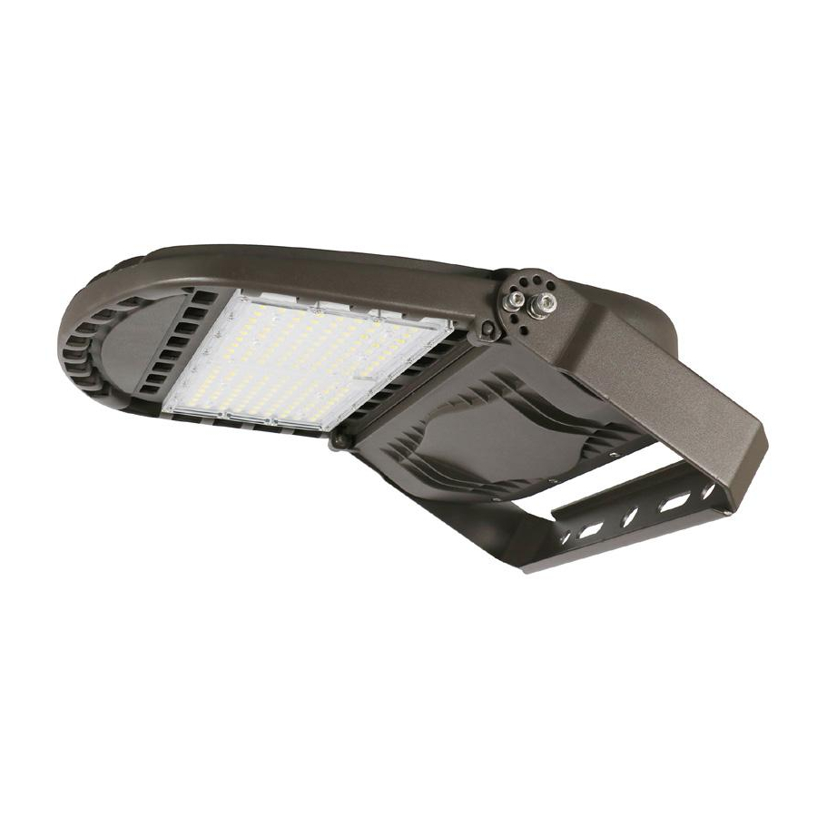
SYLVANIA ValueLED™ Area Light
PLEASE READ THE BELOW WARNING BEFORE ATTEMPTING INSTALLATION
• DO NOT USE A GENERATOR TO TEST THE LUMINAIRE.
• PLEASE ABIDE BY ALL RELEVANT NATIONAL, STATE, AND MUNICPAL SAFETY CODES WHEN
INSTALLING THIS FIXTURE.
• TO AVOID SHOCK, PLEASE DO NOT ATTEMPT INSTALLATION DURING RAIN
• INSTALLATIONS SHOULD ONLY BE ATTEMPTED BY LICENSED ELECTRICIANS.
• PLEASE WEAR GLOVES WHILE ATTEMPTING INSTALLATIONS.
• PLEASE DISCONNECT THE LUMINAIRE IF SMOKE OR FIRE IS VISIBLE DURING OR FOLLOWING
ANY INSTALLATION ATTEMPTS
For warranty information please visit :
www.sylvania.com/warrantyregistration.
WARNING
3983099
Advertisement
Table of Contents

Related Manuals for Sylvania ValueLED 61877

Summary of Contents for Sylvania ValueLED 61877
- Page 1 SYLVANIA ValueLED™ Area Light For warranty information please visit : www.sylvania.com/warrantyregistration. WARNING PLEASE READ THE BELOW WARNING BEFORE ATTEMPTING INSTALLATION • DO NOT USE A GENERATOR TO TEST THE LUMINAIRE. • PLEASE ABIDE BY ALL RELEVANT NATIONAL, STATE, AND MUNICPAL SAFETY CODES WHEN INSTALLING THIS FIXTURE.
-
Page 2: Wiring Diagram
This product has 3 dimming functions available: a) Constant Current 1-10VDC dimming, b) PWM signal dimming and c) Variable resistance dimming. Please choose the appropriate dimming function for your needs if dimming is desired. Make all wiring connections via the supplied wire leads in accordance with NEC and local codes. For units with a NEMA photocontrol receptacle, if the aiming angle will be beyond 45 above horizontal, place a continuous bead of silicone completely around the top edge of the receptacle to seal the shorting cap or photocontrol. -
Page 3: Mounting Bracket Options
MOUNTING BRACKET OPTIONS: Five mounting brackets are available to choose: INSTALLATION INSTRUCTIONS: Mounting with Slipfitter Mount (NAED 61877) : 1. Remove the adjustment bolt located on the slipfitter bracket, run the wires through the bracket and re-install the adjustment bolt securing both pieces of the bracket together (Figure 1). - Page 4 Mounting with Pole Mount (NAED 61876): 1. Remove the adjustment bolt located on the pole mount bracket, run the wires through the bracket half that attaches to the fixture. 2. Install and secure the bracket half to the fixture with the screws provided. (Figure 5). 3.
- Page 5 Pole Mount Bolt Drill Pattern Mounting with Wall Mount (NAED 61875): Run the fixture wires through the bracket (Figure 10). Install the bracket on the fixture and secure with the screws provided (Figure11). Drill holes on the wall using the dimensions provided. (Figure 12) Secure fixture to wall with (2) bolts (not included with fixture).
- Page 6 Figure 16 Figure 17 Mounting with Yoke Mount (NAED 61879): 1. Remove the bracket mounting screws on the fixture. 2. Install the bracket on the fixture using the screws provided and tighten to secure. (Figure 18) 3. Place the bracket on the surface that will support the fixture and secure with bolts and nuts (not provided) (Figure 19) Note: Mounting hardware is not included, and it is up to the installer to determine the most appropriate hardware for the desired mounting location.
-
Page 7: Dip Switch Settings
Motion Sensor Setup Instructions : To adjust the motion sensor’s settings remove the motion sensor cover by loosening it’s screws. Set the motion sensor’s settings via the DIP switches as per actual requirements. Replace the motion sensor cover and secure by tightening the screws. - Page 8 3983099...
- Page 9 Luminaire pour grande surface SYLVANIA ValueLED Pour obtenir la couverture de la garantie, enregistrez-vous sur www.sylvania.com/warrantyregistration AVERTISSEMENT VEUILLEZ LIRE TOUTES LES DIRECTIVES AVANT DE COMMENCER L’INSTALLATION • NE PAS UTILISER UN GÉNÉRATEUR POUR TESTER CE LUMINAIRE • VEUILLEZ RESPECTER TOUTES LES EXIGENCES DES CODES NATIONAUX, PROVINCIAUX ET MUNICIPAUX APPLICABLES LORS DE L’INSTALLATION DU LUMINAIRE...
-
Page 10: Schéma De Câblage
Ce produit offre 3 fonctions de gradation disponibles : a) courant constant gradation de 1-10V c.c., b) gradation à signal MID et c) gradation par résistance variable. Si vous désirez utiliser la gradation, veuillez choisir celle correspondant à vos besoins. Effectuer toutes les connexions de câblage à... -
Page 11: Directives D'installation
OPTIONS DE SUPPORT DE MONTAGE : Choix de cinq supports de montage disponibles : DIRECTIVES D’INSTALLATION : Montage à l’aide du raccord lisse (NAED 61877) : 1. Retirer le boulon de réglage logé sur le support du raccord lisse, acheminer les fils dans le support et réinstaller le boulon de réglage rattachant les deux pièces du support ensemble. - Page 12 Installation sur mât (NAED 61876): 1. Retirer le boulon de réglage situé sur le support de montage sur mât, acheminer les fils jusqu’à la première moitié du support rattaché au luminaire. 2. Installer et rattacher la première moitié du support à l’aide des vis incluses. (Figure 5) 3.
- Page 13 Figure 7 Figure 8 Figure 9 Configuration de perçage du boulon pour montage sur mât Installation murale (NAED 61875): Acheminer les fils dans le support. (Figure 10) Installer le support sur le luminaire et rattacher avec les vis incluses. (Figure11) Percer les trous sur le mur en respectant les dimensions fournies.
- Page 14 Figure 14 Figure 15 Figure 16 Figure 17 Installation avec étrier (NAED 61879): 1. Retirer les vis du support de montage sur le luminaire. 2. Installer le support sur le luminaire et rattacher avec les vis incluses. (Figure 18) 3. Positionner le support sur la surface qui reçoit le luminaire et rattacher avec les boulons et écrous (non inclus). (Figure 19) Note : les pièces de fixation de montage ne sont pas incluses, l’installateur doit déterminer quelles pièces de fixation conviennent à...
- Page 15 DIRECTIVES POUR LE CAPTEUR DE MOUVEMENT EN OPTION : Directives de configuration pour le capteur de mouvement : Pour ajuster les réglages du capteur de mouvement retirer le couvercle du capteur de mouvement en desserrant ses vis. Effectuer les réglages du capteur de mouvement à l’aide des interrupteurs DIP pour répondre aux exigences actuelles. Replacer le couvercle du capteur de mouvement et rattacher à...
- Page 16 Période d’attente Référence à la période de temps durant laquelle la lampe demeure à un faible niveau d’éclairage avant de s’éteindre complètement si l’absence des individus est longue. En mode désactivation, le faible éclairage est maintenu jusqu’à la détection de mouvement. Réglage à...