Table of Contents
Advertisement
Available languages
Available languages
Quick Links
Technical Data
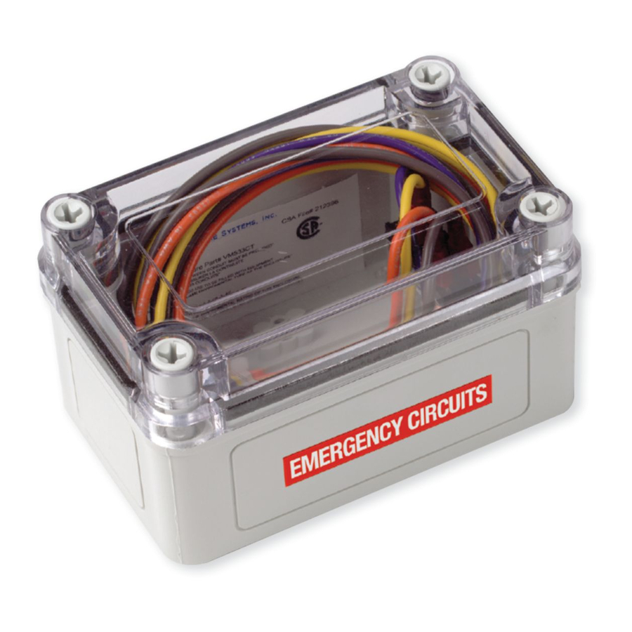
Lighting Relay Module
Module de relais pour luminaire
Módulo de relé de iluminación
WARNING: TURN POWER OFF AT CIRCUIT BREAKER BEFORE INSTALLING. ONLY QUALIFIED ELECTRICIANS
SHOULD INSTALL THE LIGHTING RELAY MODULE (LRM).
IMPORTANT SAFEGUARDS
When using electrical equipment, basic safety precautions should always be followed including the following:
READ AND FOLLOW ALL SAFETY INSTRUCTIONS
Do not use outdoors
O
O
Do not let power supply cords touch hot surfaces
O
O
Do not mount near gas or electric heaters
O
O
Equipment should be mounted in locations and heights where it will not readily be subjected to tampering by
O
O
unauthorized personnel
The use of accessory equipment not recommended by the manufacturer may cause an unsafe condition
O
O
Do not use this equipment for other than intended use
O
O
SAVE THESE INSTRUCTIONS
Introduction
The Lighting Relay Module (LRM) is listed in accordance
to UL 924 as "Emergency Lighting and Power
Equipment. " The LRM shall be used with Greengate CKM
Panels and iLumin SC Panels.
The LRM is a device that monitors a normal power circuit.
Upon sensing loss of power to its monitored circuit, it
is designed to force all relays/dimmers in the connected
Greengate CKM Panels and iLumin SC Panels to an ALL
ON or ALL OFF state regardless of the control panel
status. This allows the closure of relays and forces all
dimmers to an all on state during loss of normal power to
allow emergency power systems to feed lighting loads.
Once the relay senses the power returning, the panel will
return to normal operation.
The LRM is available in a 347 VAC model.
Model # LRM347
SAFETY INSTRUCTIONS
LRM – Greengate CKM Relay Panels
N
ote:
The transformer in the connected relay panel must
be powered from an emergency power source in
order for the LRM to operate properly.
The LED on the mother board will show an overridden
state when the LRM triggers a closure through the
external connection.
IMPORTANT: Line voltage input to the LRM must be
from the NORMAL power source.
Advertisement
Table of Contents

Related Manuals for Cooper Lighting LRM347


Summary of Contents for Cooper Lighting LRM347
- Page 1 Technical Data Model # LRM347 Lighting Relay Module Module de relais pour luminaire Módulo de relé de iluminación SAFETY INSTRUCTIONS WARNING: TURN POWER OFF AT CIRCUIT BREAKER BEFORE INSTALLING. ONLY QUALIFIED ELECTRICIANS SHOULD INSTALL THE LIGHTING RELAY MODULE (LRM). IMPORTANT SAFEGUARDS...
-
Page 2: Wiring Information
LRM to operate and press the button. properly. vi. Program the outputs to respond to the emergency Cooper Lighting scene. From the Configuration menu, highlight Solutions the “Emergency Scene Edit” option and press button. The display will show a list of the... -
Page 3: Control Wiring
Control Wiring vii. You can alter output levels collectively or individually, as required: • Collectively - Highlight the “All Outputs” option and either type the required dimming Switch Switch level using the keypad or use the Input 1 Input 2 buttons to adjust the current value for all outputs and press the button. -
Page 4: Consignes De Sécurité
Introduction CONSIGNES DE SÉCURITÉ AVERTISSEMENT: METTEZ LE DISJONCTEUR HORS TENSION AVANT DE PROCÉDER À L'INSTALLATION. SEUL UN ÉLECTRICIEN QUALIFIÉ DOIT INSTALLER LE MODULE DE RELAIS POUR LUMINAIRE (MRL). MESURES DE PROTECTION IMPORTANTES Lorsque vous utilisez un appareil électrique, vous devez toujours respecter les mesures de sécurité élémentaires, y compris les suivantes: LISEZ ET RESPECTEZ TOUTES LES CONSIGNES DE SÉCURITÉ. - Page 5 Câblage des contrôles vi. Programmez les sorties en vue des situations Cooper Lighting d'urgence. À partir du menu Configuration, Solutions sélectionnez l'option « Emergency Scene Edit », puis appuyez sur le bouton . L'affichage présentera la liste des paramètres de sortie configurés:...
- Page 6 Câblage des contrôles Entrées de Entrées de commutateur 1 commutateur 2 Entrées de contact iLumin Pour allumer en priorité: Établissez le contact sec à partir du MRL jusqu'aux entrées de commuta- Normalement teur 1 ou 2. fermé Jaune Au contact, tous les relais etgradateurs (18 AWG) sont poussés à...
-
Page 7: Instrucciones De Seguridad
Introducción INSTRUCCIONES DE SEGURIDAD ADVERTENCIA: APAGUE LA ALIMENTACIÓN DEL DISYUNTOR DEL CIRCUITO ANTES DE PROCEDER CON LA INSTALACIÓN. SOLAMENTE ELECTRICISTAS CALIFICADOS DEBEN INSTALAR EL MÓDULO DE RELÉ DE ILUMINACIÓN (LRM, POR SUS SIGLAS EN INGLÉS). MEDIDAS DE SEGURIDAD IMPORTANTES Al usar equipo eléctrico, siempre deben seguirse precauciones de seguridad básicas, entre ellas las siguientes: LEA Y SIGA TODAS LAS INSTRUCCIONES DE SEGURIDAD No utilice en exteriores No permita que los cables de alimentación toquen superficies calientes... - Page 8 SC debe recibir alimentación de una fuente de energía de emergencia. Resalte la opción "Entrar en estado de emergencia" y presione el botón Cooper Lighting vi. Programe las salidas para que respondan a la Solutions situación de emergencia. Desde el menú de Configuración, resalte la opción "Editar situación...
- Page 9 Veuillez consulter la section juridique du www.cooperlighting.com pour connaître nos conditions générales. GARANTÍAS Y LIMITACIÓN DE RESPONSABILIDAD Remítase a la sección Legal del sitio web www.cooperlighting.com para conocer nuestros términos y condiciones. Cooper Lighting Solutions is a registered trademark. All trademarks are property of their respective owners.