Table of Contents
Advertisement
Quick Links
HOW TO USE THIS MANUAL
GENERAL INFORMATION
1.
GENERAL DESCRIPTION
(a)
This manual is made in accordance with SAE J2008.
(b)
Generally, repair operations can be separated in the following 3 main processes:
1. Diagnosis
2. Removing and Installing, Replacing, Disassembling, Installing and Checking, Adjusting
3. Final Inspection
(c)
This manual explains the 1st process of "Diagnosis" (placed in the "Diagnostics" section), the 2nd pro-
cess of "Removing and Installing, Replacing, Disassembling, Installing and Checking, Adjusting", but
the 3rd process of "Final Inspection" is omitted.
(d)
The following essential operations are not written in this manual. However, these operations must be
done in the practical situation.
(1)
Operation with a jack or lift
(2)
Cleaning of a removed part when necessary
(3)
Visual check
2.
INDEX
(a)
An alphabetical INDEX is provided as a section on the end of the book to guide you to the item to be
repaired.
3.
(a)
Use of special service tools (SST) and special service materials (SSM) may be required, depending
on the repairing condition. Be sure to use SST and SSM when they are required and follow the working
procedure properly. A list of SST and SSM is in the Preparation section of this manual.
4.
REPAIR PROCEDURES
(a)
Component drawing is placed under the title when necessary.
(b)
Illustrations are placed as "disassembled parts drawing" so that it enables you to understand the fitting
condition of the components.
(c)
Non−reusable parts, grease applied parts, precoated parts and tightening torque are specified in the
components drawing.
Example:
Camshaft Timing Tube Assy
Seal Washer
Screw Plug
78 (790, 58)
15 (150, 11)
N·m (kgf·cm, ft·lbf) : Specified torque
z Non−reusable part
1CD−FTV ENGINE REPAIR MANUAL (RM1046E)
INTRODUCTION
Camshaft Drive Gear
z Camshaft Setting Oil Seal
Wave Washer
−
HOW TO USE THIS MANUAL
Camshaft,
No. 3 Camshaft Sub−assy
7.5 (80, 66 in.·lbf)
Camshaft Driven Main Gear
Camshaft Sub Gear
Snap Ring
No. 2 Camshaft,
No. 4 Camshaft Sub−assy
Camshaft Timing Gear
Bolt Washer
01−1
010B2−19
A54988
Advertisement
Table of Contents

Related Manuals for Toyota 1CD-FTV


Summary of Contents for Toyota 1CD-FTV
- Page 1 01−1 − INTRODUCTION HOW TO USE THIS MANUAL HOW TO USE THIS MANUAL 010B2−19 GENERAL INFORMATION GENERAL DESCRIPTION This manual is made in accordance with SAE J2008. Generally, repair operations can be separated in the following 3 main processes: 1. Diagnosis 2.
- Page 2 01−2 − INTRODUCTION HOW TO USE THIS MANUAL Tightening torque, oil applying position, and non−reusable parts are described as important points in the procedure. NOTICE: There are cases where such information can only be indicated by an illustration. In that case, all the information such as torque, oil, etc.
- Page 3 01−3 − INTRODUCTION HOW TO USE THIS MANUAL SI UNIT The UNITS given in this manual are primarily expressed according to the SI UNIT (International Sys- tem of Unit), and alternately expressed in the metric system and in the English System. Example: Torque: 30 N×m (310 kgf×cm, 22 ft×lbf) 1CD−FTV ENGINE REPAIR MANUAL (RM1046E)
- Page 4 01−4 − INTRODUCTION REPAIR INSTRUCTION REPAIR INSTRUCTION 010R3−01 PRECAUTION TO PREVENT FROM ENTERING FOREIGN SUBSTANCES. When foreign substances such as dust, grain of sand or metallic dust enter inside of engine, it often causes functional failure of the engine. Precaution before disassembly. Remove adequately all sand and mud adhere to the outside of engine .
- Page 5 01−5 − INTRODUCTION REPAIR INSTRUCTION NOTICE: Do the torque checking with the lower limit value of the torque tolerance. Depending on the seal lock agent to apply, there may be a case where it is necessary to leave it for a specified time until it hardens. Gaskets: When necessary, use a sealer on gaskets to prevent leaks.
- Page 6 01−6 − INTRODUCTION REPAIR INSTRUCTION Never use any electric equipment like an electric motor or a working light as they may cause spark or high temperature. Never use an iron hammer as it may cause spark. Dispose the shop lag separately from any fuel deposit. REMOVAL AND INSTALLATION OF ENGINE INTAKE PARTS If any metal tip is mixed in the inlet pass, that may give a...
- Page 7 01−7 − INTRODUCTION TERMS TERMS 010B9−17 ABBREVIATIONS USED IN MANUAL Abbreviations Meaning Anti−Lock Brake System Air Conditioner Alternating Current Accessory ACIS Acoustic Control Induction System ACSD Automatic Cold Start Device A.D.D. Automatic Disconnecting Differential Air−Fuel Ratio Active Height Control Suspension Automatic Locking Retractor Alternator Amplifier...
- Page 8 01−8 − INTRODUCTION TERMS Abbreviations Meaning Defogger Deflector DIFF. Differential DIFF. LOCK Differential Lock D/INJ Direct Injection Data Link Connector Distributorless Ignition DOHC Double Overhead Camshaft Dash Pot Dead Soak Digital Signal Processor Diagnostic Trouble Code Digital Versatile Disc Electric Brake Force Distribution ECAM Engine Control And Measurement System Electronic Controlled Diesel...
- Page 9 01−9 − INTRODUCTION TERMS Abbreviations Meaning H−FUSE High Current Fuse High High Intensity Discharge (Head Lamp) Housing Hard Top Heated Windshield System Integrated Circuit Indirect Diesel Injection Independent Front Suspension Ignition Integrated Ignition Assembly Intake (Manifold, Valve) Intermittent Instrument Panel Independent Rear Suspension Idle Speed Control Junction Block...
- Page 10 Special Service Tools Standard Cold−Start Fuel Injection Switch System Transaxle TACH Tachometer Throttle Body Electronic Fuel Injection Turbocharger TCCS TOYOTA Computer−Controlled System Timing Control Valve Top Dead Center TEMP. Temperature TEMS TOYOTA Electronic Modulated Suspension 1CD−FTV ENGINE REPAIR MANUAL (RM1046E)
- Page 11 − INTRODUCTION TERMS Abbreviations Meaning Toyota Free−Tronic Total Information System For Vehicle Development Transmission TOYOTA Motor Corporation TMMK TOYOTA Motor Manufacturing Kentucky, Inc. Traction Control System TURBO Turbocharge Three−Way Catalyst Underdrive Undersize Vacuum Control Valve VENT Ventilator Vehicle Identification Number...
- Page 12 INTRODUCTION TERMS 010BA−20 GLOSSARY OF SAE AND TOYOTA TERMS This glossary lists all SAE−J1930 terms and abbreviations used in this manual in compliance with SAE rec- ommendations, as well as their TOYOTA equivalents. TOYOTA TERMS SAE TERMS ABBREVIATIONS ( )−−ABBREVIATIONS...
- Page 13 01−13 − INTRODUCTION TERMS HO2S Heated Oxygen Sensor Heated Oxygen Sensor (HO Idle Air Control Idle Speed Control (ISC) Intake Air Temperature Intake or Inlet Air Temperature − Ignition Control Module Indirect Fuel Injection Indirect Injection (IDL) − Inertia Fuel−Shutoff −...
- Page 14 01−14 − INTRODUCTION TERMS Transmission Control Module Transmission ECU, ECT ECU Throttle Position Throttle Position − Transmission Range Bimetallic Vacuum Switching Valve (BVSV) Thermal Vacuum Valve Thermostatic Vacuum Switching Valve (TVSV) Three−Way Catalytic (TWC) Three−Way Catalytic Converter Manifold Converter TWC+OC Three−Way + Oxidation Catalytic Converter + CCo Volume Air Flow...
- Page 15 02−1 − PREPARATION INTAKE INTAKE 023FS−01 PREPARATION Turbocharger Pressure Gauge TURBOCHARGER 09992−00242 SUB−ASSY(1CD−FTV)(From September, 2003) 1CD−FTV ENGINE REPAIR MANUAL (RM1046E)
- Page 16 02−2 − PREPARATION ENGINE MECHANICAL ENGINE MECHANICAL 023EZ−01 PREPARATION Oil Pan Seal Cutter PARTIAL ENGINE 09032−00100 ASSY(1CD−FTV)(From September, 2003) 09201−10000 Valve Guide Bushing Remover & CYLINDER HEAD Replacer Set ASSY(1CD−FTV)(From September, 2003) Valve Guide Bushing Remover & CYLINDER HEAD (09201−01060) Replacer 6 ASSY(1CD−FTV)(From September,...
- Page 17 02−3 − PREPARATION ENGINE MECHANICAL Replacer ”A” PARTIAL ENGINE (09316−00021) ASSY(1CD−FTV)(From September, 2003) Puller C Set PARTIAL ENGINE 09950−50013 ASSY(1CD−FTV)(From September, 2003) Hanger 150 (09951−05010) PARTIAL ENGINE ASSY(1CD−FTV)(From September, 2003) (09952−05010) Slide Arm PARTIAL ENGINE ASSY(1CD−FTV)(From September, 2003) Center Bolt 100 PARTIAL ENGINE (09953−05010)
- Page 18 02−4 − PREPARATION ENGINE MECHANICAL Handle 100 PARTIAL ENGINE (09951−07100) ASSY(1CD−FTV)(From September, 2003) CYLINDER HEAD ASSY(1CD−FTV)(From September, 2003) CYLINDER BLOCK ASSY(1CD−FTV)(From September, 2003) Variable Pin Wrench Set PARTIAL ENGINE 09960−10010 ASSY(1CD−FTV)(From September, 2003) Variable Pin Wrench Arm Assy PARTIAL ENGINE (09962−01000) ASSY(1CD−FTV)(From September,...
- Page 19 02−5 − PREPARATION ENGINE MECHANICAL Equipment V−block Piston ring compressor Piston ring expander Valve seat cutter Hexagon wrench (6 mm) Hexagon wrench (8 mm) Connecting rod aligner Cylinder gauge Dial indicator Feeler gauge Micrometer Precision straight edge Steel square Torque wrench Vernier calipers Dial indicator with magnetic base Slide calipers...
- Page 20 02−6 − PREPARATION LUBRICATION LUBRICATION 023F0−01 PREPARATION Equipment Feeler gauge 1CD−FTV ENGINE REPAIR MANUAL (RM1046E)
- Page 21 02−7 − PREPARATION STARTING & CHARGING STARTING & CHARGING 023FT−01 PREPARATION Alternator Pulley Wrench Set GENERATOR 09820−63020 ASSY(1CD−FTV)(From September, 2003) Puller B Set GENERATOR 09950−40011 ASSY(1CD−FTV)(From September, 2003) Hanger 200 GENERATOR (09951−04020) ASSY(1CD−FTV)(From September, 2003) Slide Arm GENERATOR (09952−04010) ASSY(1CD−FTV)(From September, 2003) Center Bolt 150...
- Page 22 02−8 − PREPARATION STARTING & CHARGING Handle Set GENERATOR 09950−70010 ASSY(1CD−FTV)(From September, 2003) Handle 100 GENERATOR (09951−07100) ASSY(1CD−FTV)(From September, 2003) Equipment Ohmmeter Torque wrench Vernier calipers Pull scale V−block Dial indicator with magnetic base 1CD−FTV ENGINE REPAIR MANUAL (RM1046E)
- Page 23 03−1 − SERVICE SPECIFICATIONS STANDARD BOLT STANDARD BOLT 030LK−08 HOW TO DETERMINE BOLT STRENGTH Bolt Type Hexagon Head Bolt Class Stud Bolt Weld Bolt Normal Recess Bolt Deep Recess Bolt No Mark No Mark No Mark w/ Washer w/ Washer B06431 1CD−FTV ENGINE REPAIR MANUAL (RM1046E)
- Page 24 03−2 − SERVICE SPECIFICATIONS STANDARD BOLT 030LL−08 SPECIFIED TORQUE FOR STANDARD BOLTS Specified torque Diameter Pitch Hexagon head bolt Hexagon flange bolt Class Class N·m kgf·cm ft·lbf N·m kgf·cm ft·lbf 48 in.·lbf 52 in.·lbf 1.25 12.5 1.25 1.25 1,150 − −...
- Page 25 03−3 − SERVICE SPECIFICATIONS STANDARD BOLT 030LM−08 HOW TO DETERMINE NUT STRENGTH Nut Type Old Standard Hexagon Nut Present Standard Class Hexagon Nut Cold Forging Nut Cutting Processed Nut No Mark 5N (4T) No Mark (w/ Washer) No Mark (w/ Washer) No Mark 7N (5T) 10N (7T)
- Page 26 03−4 − SERVICE SPECIFICATIONS INTAKE INTAKE 031FQ−03 SERVICE DATA Actuator push rod Standard stroke 50 kpa (375 mmHg, 15 in. Hg) 0.2 mm (0.008 in.) 30 kpa (225 mmHg, 9 in. Hg) 5.0 mm (0.197 in.) 1CD−FTV ENGINE REPAIR MANUAL (RM1046E)
- Page 27 03−5 − SERVICE SPECIFICATIONS ENGINE MECHANICAL ENGINE MECHANICAL 031H1−03 SERVICE DATA Valve clearance Intake (cold) 0.20 to 0.30 mm (0.008 to 0.012 in.) Exhaust 0.35 to 0.45 mm (0.014 to 0.018 in.) Adjusting shim thickness Mark 2.500 2.500 mm (0.0984 in.) Mark 2.550 2.550 mm (0.1004 in.) Mark 2.600...
- Page 28 03−6 − SERVICE SPECIFICATIONS ENGINE MECHANICAL Camshaft Circle runout Maximum 0.06 mm (0.0024 in.) Cam lobe height (intake) Standard 46.57 to 46.67 mm (1.8335 to 1.8374 in.) Minimum 46.10 mm (1.8150 in.) Cam lobe height (exhaust) Standard 47.52 to 47.62 mm (1.8709 to 1.8748 in.) Minimum 47.05 mm (1.8524 in.) 26.969 to 26.985 mm (1.0618 to 1.0624 in.)
- Page 29 03−7 − SERVICE SPECIFICATIONS ENGINE MECHANICAL 031H2−03 TORQUE SPECIFICATION Part Tightened N×m kgf×cm ft×lbf Cylinder block water drain cock x Cylinder block Oil check valve x Cylinder block Engine rear oil seal retainer x Cylinder block 65 in.×lbf Oil pump x Cylinder block Oil pan x Cylinder block (See page 14−4)
- Page 30 03−8 − SERVICE SPECIFICATIONS LUBRICATION LUBRICATION 031H5−03 SERVICE DATA Oil pump Tip clearance Standard 0.08 to 0.20 mm (0.0031 to 0.0079 in.) Body clearance Standard 0.10 to 0.20 mm (0.0039 to 0.0079 in.) 1CD−FTV ENGINE REPAIR MANUAL (RM1046E)
- Page 31 03−9 − SERVICE SPECIFICATIONS STARTING & CHARGING STARTING & CHARGING 031E6−04 SERVICE DATA Starter armature assy Circle runout Maximum 0.05 mm (0.0020 in.) Diameter Standard 35.0 mm (1.378 in.) Minimum 34.0 mm (1.339 in.) Undercut depth Standard 0.6 mm (0.024 in.) Minimum 0.2 mm (0.008 in.) Brush...
- Page 32 03−10 − SERVICE SPECIFICATIONS STARTING & CHARGING 031E7−05 TORQUE SPECIFICATION Part Tightened N×m kgf×cm ft×lbf Starter commutator end frame assy x Starter brush holder assy 33 in.×lbf Starter drive housing assy x Starter commutator end frame assy 53 in.×lbf Magnetic switch x Starter drive housing assy 20 in.×lbf Magnetic switch x Lead wire 52 in.×lbf...
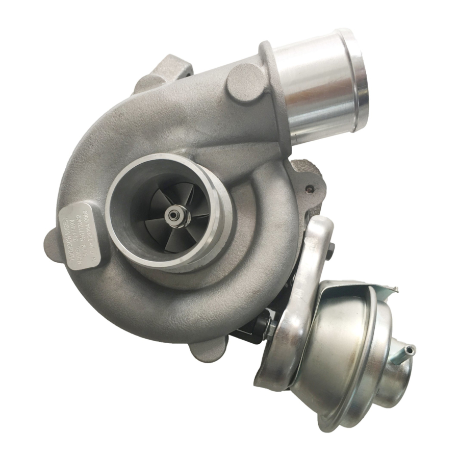
- Page 33 13−1 − INTAKE TURBOCHARGER SUB−ASSY (1CD−FTV)(From September, 2003) TURBOCHARGER SUB−ASSY (1CD−FTV)(From September, 2003) 1308O−01 INSPECTION INSPECT TURBINE SHAFT Check the operation. Grasp the edge of the turbine shaft, then turn it. Check that the turbine shaft turns smoothly. Turn If the turbine shaft does not turn or it turns with heavy drag, re- place the turbocharger.
- Page 34 14−1 − ENGINE MECHANICAL PARTIAL ENGINE ASSY (1CD−FTV)(From September, 2003) PARTIAL ENGINE ASSY (1CD−FTV)(From September, 2003) 141NP−01 COMPONENTS 20 (204, 15) z Nozzle Holder Oil Filler Cap Sub−assy z Gasket 18 (184, 13) Seal Nozzle Leakage Pipe Assy 13 (135, 10) Cylinder Head Cover Sub−assy 27 (275, 20)
- Page 35 14−2 − ENGINE MECHANICAL PARTIAL ENGINE ASSY (1CD−FTV)(From September, 2003) Exhaust Fuel Addition Injector Assy 12 (117, 8.5) See page 14−4 Nozzle Holder 1st 45 (460, 33) Clamp 2nd Turn 90_ 3rd Turn 90_ 4th Turn 90_ z O−ring z Gasket Plate Washer Cylinder Head Sub−assy z Cylinder Head Gasket...
- Page 36 14−3 − ENGINE MECHANICAL PARTIAL ENGINE ASSY (1CD−FTV)(From September, 2003) Water Pump Assy z Gasket 31 (320, 23) Cylinder Block Water Drain Cock Sub−assy Engine Rear Oil Seal Retainer z Oil Seal Oil Pump Assy z Gasket 7.4 (75, 65 in.·lbf) z Gasket 33 (331, 24) z Oil Seal...
- Page 37 14−4 − ENGINE MECHANICAL PARTIAL ENGINE ASSY (1CD−FTV)(From September, 2003) 141NQ−01 OVERHAUL REMOVE OIL FILLER CAP SUB−ASSY REMOVE NOZZLE HOLDER SEAL Using a screwdriver, pry out the 4 nozzle holder seals. A85935 REMOVE CYLINDER HEAD COVER SUB−ASSY Remove the 10 bolts, cylinder head cover and gasket. A85933 REMOVE NOZZLE LEAKAGE PIPE ASSY Remove the 4 hollow screws and bolt.
- Page 38 14−5 − ENGINE MECHANICAL PARTIAL ENGINE ASSY (1CD−FTV)(From September, 2003) REMOVE INJECTOR ASSY Remove the 4 injectors from the cylinder head. HINT: Arrange the injectors in the correct order. A87964 REMOVE EXHAUST FUEL ADDITION INJECTOR ASSY Using a Torx socket wrench (T40), remove the Torx screw. Remove the nozzle holder clamp, addition injector and gasket.
- Page 39 14−6 − ENGINE MECHANICAL PARTIAL ENGINE ASSY (1CD−FTV)(From September, 2003) REMOVE CRANKSHAFT TIMING PULLEY If the timing pulley cannot be removed by hand, use SST to remove the pulley. 09950−50013 (09951−05010, 09952−05010, 09953−05010, 09953−05020, 09954−05021) A57096 REMOVE CAMSHAFT OIL SEAL RETAINER Remove the 4 bolts.
- Page 40 14−7 − ENGINE MECHANICAL PARTIAL ENGINE ASSY (1CD−FTV)(From September, 2003) REMOVE CYLINDER HEAD SUB−ASSY Using several steps, loosen the 18 cylinder head bolts uniformly in the sequence shown in the illustration. Re- move the 18 cylinder head bolts and plate washers. NOTICE: Removing the bolts in a wrong order could cause warpage or cracks of the cylinder head.
- Page 41 14−8 − ENGINE MECHANICAL PARTIAL ENGINE ASSY (1CD−FTV)(From September, 2003) REMOVE OIL REGULATOR ASSY Remove the 2 bolts and oil regulator. A85936 REMOVE OIL PAN INSULATOR Remove the bolt and oil pan insulator. B08009 REMOVE OIL PAN SUB−ASSY Remove the 19 bolts and 3 nuts. A56697 Using a screwdriver, remove the oil pan by prying be- tween the cylinder block and No.
- Page 42 14−9 − ENGINE MECHANICAL PARTIAL ENGINE ASSY (1CD−FTV)(From September, 2003) REMOVE ENGINE REAR OIL SEAL RETAINER Remove the 6 bolts. Using a screwdriver, remove the oil seal retainer by prying between the oil seal retainer and main bearing cap. NOTICE: Be careful not to damage the oil seal retainer and main bearing cap.
- Page 43 14−10 − ENGINE MECHANICAL PARTIAL ENGINE ASSY (1CD−FTV)(From September, 2003) REMOVE CRANKSHAFT SEAL Using a screwdriver and hammer, tap out the oil seal. B07976 INSTALL CRANKSHAFT SEAL Using SST and a hammer, tap in a new oil seal until its sur- face is flush with the oil pump edge.
- Page 44 14−11 − ENGINE MECHANICAL PARTIAL ENGINE ASSY (1CD−FTV)(From September, 2003) INSTALL CYLINDER BLOCK WATER DRAIN COCK Seal Packing SUB−ASSY Apply seal packing to the 2 or 3 threads. Seal packing: Part No. 08826−00100 or equivalent P12477 Install the drain union. Torque: 29 N×m (291 kgf×cm, 21 ft×lbf) HINT: After applying the specified torque, if the drain pipe of the drain...
- Page 45 14−12 − ENGINE MECHANICAL PARTIAL ENGINE ASSY (1CD−FTV)(From September, 2003) INSTALL OIL PUMP ASSY New Gasket Seal Width Apply seal packing to the oil pump as shown in the illustra- 2 to 4 mm tion. (0.08 to 0.16 in.) Seal packing: Part No. 08826−00080 or equivalent Seal Packing NOTICE:...
- Page 46 14−13 − ENGINE MECHANICAL PARTIAL ENGINE ASSY (1CD−FTV)(From September, 2003) INSTALL OIL PAN SUB−ASSY Apply seal packing to the No. 1 oil pan as shown in the illustration. Seal packing: Part No. 08826−00080 or equivalent NOTICE: Seal Width Install a nozzle of which opening is cut to 4 to 7 mm 4 to 7 mm (0.16 to 0.28 in.).
- Page 47 14−14 − ENGINE MECHANICAL PARTIAL ENGINE ASSY (1CD−FTV)(From September, 2003) INSTALL OIL PAN SUB−ASSY NO.2 Apply seal packing to the oil pan as shown in the illustra- tion. Seal packing: Part No. 08826−00080 or equivalent Seal Width 4 to 7 mm NOTICE: (0.16 to 0.28 in.) Install a nozzle of which opening is cut to 4 to 7 mm...
- Page 48 14−15 − ENGINE MECHANICAL PARTIAL ENGINE ASSY (1CD−FTV)(From September, 2003) Select a new cylinder head gasket. HINT: There are 5 sizes of new cylinder head gaskets, marked ”A”, ”B”, ”C”, ”D”, and ”E”. New cylinder head gasket thickness: 0.85 to 0.95 mm (0.0335 to 0.0374 in.) 0.90 to 1.00 mm (0.0354 to 0.0394 in.) 0.95 to 1.05 mm (0.0374 to 0.0413 in.) 1.00 to 1.10 mm (0.0394 to 0.0433 in.)
- Page 49 14−16 − ENGINE MECHANICAL PARTIAL ENGINE ASSY (1CD−FTV)(From September, 2003) Install the cylinder head bolts. HINT: The cylinder head bolts are tightened in 4 successive steps (steps (3), (5), (6) and (7)). If the cylinder head bolt is broken or deformed, replace it with a new bolt.
- Page 50 14−17 − ENGINE MECHANICAL PARTIAL ENGINE ASSY (1CD−FTV)(From September, 2003) Install the camshaft. Apply engine oil to the cam and gear of the camshaft, and the journal of the camshaft carrier. Place the intake camshaft on the camshaft carrier as shown in the illustration so that the No.
- Page 51 14−18 − ENGINE MECHANICAL PARTIAL ENGINE ASSY (1CD−FTV)(From September, 2003) INSPECT VALVE CLEARANCE Upward Turn the crankshaft so that the cam lobe located over the Cam Lobe inspecting valve faces upward. Using a feeler gauge, measure the clearance between the valve lifter and camshaft. Clearance A09687 Measure the clearance at 16 places.
- Page 52 14−19 − ENGINE MECHANICAL PARTIAL ENGINE ASSY (1CD−FTV)(From September, 2003) Select the size of an adjusting shim to replace by following the formula or the charts: Using a micrometer, measure the thickness of the removed shim. Calculate the thickness of a new shim so that the valve clearance comes within the specified value.
- Page 53 14−20 − ENGINE MECHANICAL PARTIAL ENGINE ASSY (1CD−FTV)(From September, 2003) Adjusting Shim Selection Chart (Intake) New Shim Thickness mm (in.) Shim Shim Thickness Thickness 2.500(0.0984) 2.950(0.1161) 3.000(0.1181) 2.550 (0.1004) 3.050(0.1201) 2.600 (0.1024) 3.100(0.1220) 2.650 (0.1043) 2.700 (0.1063) 3.150 (0.1240) 2.750 (0.1083) 3.200(0.1260) 2.800 (0.1102) 3.250 (0.1280)
- Page 54 14−21 − ENGINE MECHANICAL PARTIAL ENGINE ASSY (1CD−FTV)(From September, 2003) Adjusting Shim Selection Chart (Exhaust) New Shim Thickness mm (in.) Shim Shim Thickness Thickness 2.500(0.0984) 2.950(0.1161) 3.000(0.1181) 2.550 (0.1004) 3.050(0.1201) 2.600 (0.1024) 3.100(0.1220) 2.650 (0.1043) 2.700 (0.1063) 3.150 (0.1240) 2.750 (0.1083) 3.200(0.1260) 2.800 (0.1102) 3.250 (0.1280)
- Page 55 14−22 − ENGINE MECHANICAL PARTIAL ENGINE ASSY (1CD−FTV)(From September, 2003) Install the new adjusting shim. Place the new adjusting shim on the valve lifter. SST (A) Using SST (A), press down the valve lifter and re- SST (B) move SST (B). 09248−55050 (09248−05510, 09248−05520) Recheck the valve clearance.
- Page 56 14−23 − ENGINE MECHANICAL PARTIAL ENGINE ASSY (1CD−FTV)(From September, 2003) INSTALL TIMING BELT IDLER SUB−ASSY NO.2 Install the idler pulley with the bolt. Torque: 47 N×m (475 kgf×cm, 34 ft×lbf) Turn Check that the idler pulley moves smoothly. A57102 INSTALL TIMING BELT IDLER SUB−ASSY NO.1 8 mm Using an 8 mm hexagon wrench, install the plate washer Hexagon...
- Page 57 14−24 − ENGINE MECHANICAL PARTIAL ENGINE ASSY (1CD−FTV)(From September, 2003) Install the nozzle holder clamp as shown in the illustration. Tighten the camshaft bearing cap bolt by hand to fix the nozzle holder clamp. NOTICE: Pay attention to the mounting orientation of the wash- When temporarily attaching the nozzle holder clamp and mounting bolt, be careful not to orient them at an angle.
- Page 58 14−25 − ENGINE MECHANICAL PARTIAL ENGINE ASSY (1CD−FTV)(From September, 2003) Using SST (a turbocharger pressure gauge), attach SST to the fuel return side of the nozzle leakage New Gasket pipe, then maintain 100 kPa (1.0 kgf/cm , 14.5 psi) of pressure for 60 seconds to check that there are no bubbles from the pipe connection.
- Page 59 14−42 − ENGINE MECHANICAL CYLINDER BLOCK ASSY (1CD−FTV)(From September, 2003) CYLINDER BLOCK ASSY (1CD−FTV)(From September, 2003) 141NT−01 COMPONENTS No. 1 Piston Ring No. 2 Piston Ring Oil Ring Coil z Snap Ring Piston Piston Pin z Snap Ring Connecting Rod 9.0 (92, 78 in.·lbf) Cylinder Block Oil Orifice...
- Page 60 14−43 − ENGINE MECHANICAL CYLINDER BLOCK ASSY (1CD−FTV)(From September, 2003) 141NU−01 OVERHAUL INSPECT CONNECTING ROD THRUST CLEARANCE Using a dial indicator, measure the thrust clearance while moving the connecting rod back and forth. Standard thrust clearance: 0.08 to 0.40 mm (0.0031 to 0.0157 in.) If the thrust clearance is greater than maximum, replace the connecting rod assembly(s).
- Page 61 14−44 − ENGINE MECHANICAL CYLINDER BLOCK ASSY (1CD−FTV)(From September, 2003) Match the numbered connecting rod cap with the con- Front Mark necting rod. (Protrusion) Install the connecting rod cap with the front mark facing forward. Apply a light coat of engine oil to the threads and under- heads of the connecting rod cap bolts.
- Page 62 14−45 − ENGINE MECHANICAL CYLINDER BLOCK ASSY (1CD−FTV)(From September, 2003) If using the standard bearing, replace it with one having the same number. If the number of the bearing cannot be determined, find the correct number of the bearing by ad- ding together the numbers imprinted on the crankshaft and connecting rod cap, then select the bearing with the same number as the total.
- Page 63 14−46 − ENGINE MECHANICAL CYLINDER BLOCK ASSY (1CD−FTV)(From September, 2003) INSPECT CRANKSHAFT THRUST CLEARANCE Using a dial indicator, measure the thrust clearance while prying the crankshaft back and forth with a screwdriver. Standard thrust clearance: 0.040 to 0.300 mm (0.0016 to 0.0118 in.) If the thrust clearance is greater than maximum, replace the thrust washer as a set.
- Page 64 14−47 − ENGINE MECHANICAL CYLINDER BLOCK ASSY (1CD−FTV)(From September, 2003) REMOVE CYLINDER BLOCK OIL ORIFICE Using a hexagon wrench (6 mm), remove the oil orifice. 6 mm Hexagon Wrench A87939 REMOVE PISTON RING SET Using a piston ring expander, remove the No. 1 and No. 2 piston ring and oil ring.
- Page 65 14−48 − ENGINE MECHANICAL CYLINDER BLOCK ASSY (1CD−FTV)(From September, 2003) INSPECT CYLINDER BLOCK FOR FLATNESS Using a precision straight edge and feeler gauge, mea- sure the warpage on the surface which contacts the cylin- der head gasket. Maximum warpage: 0.05 mm (0.0020 in.) If the warpage is greater than maximum, replace the cylinder block.
- Page 66 14−49 − ENGINE MECHANICAL CYLINDER BLOCK ASSY (1CD−FTV)(From September, 2003) Subtract the piston diameter measurement from the cylin- der bore diameter measurement. Standard oil clearance: 0.068 to 0.140 mm (0.0027 to 0.0055 in.) If the oil clearance is greater than maximum, replace all the 4 pistons.
- Page 67 14−50 − ENGINE MECHANICAL CYLINDER BLOCK ASSY (1CD−FTV)(From September, 2003) Inspect the twist. Maximum twist: 0.15 mm (0.0059 in.) per 100 mm (3.94 in.) If the twist is greater than maximum, replace the connecting rod assembly. Z00065 INSPECT RING GROOVE CLEARANCE Using a feeler gauge, measure the clearance between a new piston ring and wall of the ring groove.
- Page 68 14−51 − ENGINE MECHANICAL CYLINDER BLOCK ASSY (1CD−FTV)(From September, 2003) INSPECT CONNECTING ROD BOLT 20 mm (0.79 in.) Using vernier calipers, measure the tension portion diam- eter. Standard diameter: 8.0 to 8.3 mm (0.315 to 0.327 in.) If the diameter is less than minimum, replace the connecting rod bolt.
- Page 69 14−52 − ENGINE MECHANICAL CYLINDER BLOCK ASSY (1CD−FTV)(From September, 2003) Install the bearing on the cylinder block and bearing cap. HINT: Each upper bearing has an oil groove and oil hole and each low- er bearing does not. Align the bearing claw with the claw groove of the cylinder clock, then push in the 5 upper bearings.
- Page 70 14−53 − ENGINE MECHANICAL CYLINDER BLOCK ASSY (1CD−FTV)(From September, 2003) Install the 5 main bearing caps in their proper locations. HINT: Each bearing cap has a number and front mark. A56043 Apply a light coat of engine oil to the threads and under the heads of the main bearing cap bolts.
- Page 71 14−54 − ENGINE MECHANICAL CYLINDER BLOCK ASSY (1CD−FTV)(From September, 2003) If using the standard bearing, replace it with one having the same number. If the number of the bearing cannot be determined, find the correct number of the bearing by ad- ding together the numbers imprinted on the cylinder block and crankshaft, then select the bearing with the same No.
- Page 72 14−55 − ENGINE MECHANICAL CYLINDER BLOCK ASSY (1CD−FTV)(From September, 2003) INSTALL TIGHT PLUG Apply adhesive around new tight plugs. Adhesive: Part No.08833 − 00070, THREE BOND 1324 or equivalent. Using SST, tap in the tight plugs as shown tn the illustra- tion.
- Page 73 14−56 − ENGINE MECHANICAL CYLINDER BLOCK ASSY (1CD−FTV)(From September, 2003) INSTALL RING PIN Using a plastic−faced hammer, tap in new ring pins until their protrusion heights are as specified. Cylinder Head Side: Lower Side: Front Side: 8 mm Protrusion Height: 5.0 mm (0.197 in.) (0.315 in.) 11 mm (0.433 in.) 20 mm...
- Page 74 14−57 − ENGINE MECHANICAL CYLINDER BLOCK ASSY (1CD−FTV)(From September, 2003) INSTALL STRAIGHT PIN Using a plastic−faced hammer, tap in new straight pins. Standard protrusion: 13 mm (0.5118 in.) for straight pin A 4.0 mm (0.1575 in.) for straight pin B 5.0 mm (0.1968 in.) for straight pin C Rear Side: Exhaust Side:...
- Page 75 14−58 − ENGINE MECHANICAL CYLINDER BLOCK ASSY (1CD−FTV)(From September, 2003) INSTALL CYLINDER BLOCK OIL ORIFICE Using a hexagon wrench (6 mm), install the oil orifice. Torque: 9.0 N×m (92 kgf×cm, 80 in.×lbf) 6 mm Hexagon Wrench A87939 INSTALL SUB−ASSY OIL NOZZLE NO.1 Install the 4 oil nozzles with the 4 bolts.
- Page 76 14−59 − ENGINE MECHANICAL CYLINDER BLOCK ASSY (1CD−FTV)(From September, 2003) Install the 2 thrust washers on the No. 3 bearing cap with the oil grooves facing outward. Groove A09512 Install the 5 main bearing caps in their proper locations. HINT: Each bearing cap has a number and font mark.
- Page 77 14−60 − ENGINE MECHANICAL CYLINDER BLOCK ASSY (1CD−FTV)(From September, 2003) INSTALL CONNECTING ROD BEARING Align the bearing claw with the groove of the connecting rod or connecting cap. Install the bearings in the connecting rod and connecting rod cap. INSTALL PISTON RING SET Install the coil by hand.
- Page 78 14−61 − ENGINE MECHANICAL CYLINDER BLOCK ASSY (1CD−FTV)(From September, 2003) Match the numbered connecting rod cap with the con- Front Mark necting rod. (Protrusion) Install the connecting rod cap with the front mark facing forward. Apply a light coat of engine oil to the threads and under- heads of the connecting rod cap bolts.
- Page 79 16−1 − COOLING WATER PUMP ASSY (1CD−FTV)(From September, 2003) WATER PUMP ASSY (1CD−FTV)(From September, 2003) 160T5−01 INSPECTION INSPECT WATER PUMP ASSY Visually check the drain hole for coolant leakage. Turn If leakage is found, replace the water pump. Turn the pulley, then check that the water pump bearing moves smoothly without making a noise.
- Page 80 17−1 − LUBRICATION OIL PUMP ASSY (1CD−FTV)(From September, 2003) OIL PUMP ASSY (1CD−FTV)(From September, 2003) 170J0−01 INSPECTION INSPECT OIL PUMP ASSY Inspect the tip clearance. Using a feeler gauge, measure the clearance be- tween the drive and driven rotor tips. Standard tip clearance: 0.08 to 0.20 mm (0.0031 to 0.0079 in.) A55604...
- Page 81 19−1 − STARTING & CHARGING STARTER ASSY (1CD−FTV)(From September, 2003) STARTER ASSY (1CD−FTV)(From September, 2003) 190VA−01 COMPONENTS Starter Armature Assy Starter Brush Holder Assy Starter Commutator End Frame Assy 6.0 (61, 53 in.·lbf) 3.8 (39, 33 in.·lbf) 6.0 (61, 53 in.·lbf) 2.3 (23, 20 in.·lbf) Starter Magnetic Switch Assy...