Table of Contents
Advertisement
Release Date:
April 13, 2021
Revision:
CD-200134-00 v2.0
This document contains "Technical Data", as defined under the Export Administration Regulations (EAR)
(15 CFR Part 772)
and, as such, may not be exported, disclosed, or otherwise transferred to any non-"U.S.
Person" as defined under the EAR (15 CFR Part 772) without the prior written authorization of the U.S.
Government and review/approval from Iridium's Director, Compliance & Security.
Iridium Edge
Development Kit Guide
Pro
®
Advertisement
Table of Contents

Related Manuals for Iridium Edge Pro


Summary of Contents for Iridium Edge Pro
- Page 1 Person” as defined under the EAR (15 CFR Part 772) without the prior written authorization of the U.S. Government and review/approval from Iridium’s Director, Compliance & Security.
- Page 2 Document and materials and/or revise this Document or withdraw it at any time. The Iridium Partner assumes any and all risks of using the Product and any information provided in this Document.
-
Page 3: Revision History
Initial version v2.0 13 April 2021 Minor updates for Iridium Edge Pro release package version 2 Controlled for export under the EAR. See front cover for use and disclosure statement. Iridium Satellite LLC Proprietary and Confidential Information CD-200134-00 Iridium Edge Pro Development Kit Guide v2.0... -
Page 4: Table Of Contents
2.11 Serial to USB Converter ..................14 Setting up the Hardware .................... 15 Connecting the TIC to the Iridium Edge Pro ............15 Powering the TIC and Edge Pro ................16 Connecting the TIC to PC ..................18 Connecting to the PC ..................... 19 Test Interface Card ..................... -
Page 5: Introduction
This document is a technical document that targets software and hardware developers who want to develop and test Iridium Edge Pro applications. Partners using this document should have an Iridium Edge Pro Development kit and access to the Iridium Edge Pro software tools posted on Iridium-For-Partners (IFP). -
Page 6: Contents
Service Provider. An Iridium partner than sells Iridium satellite services Value-Added Resellers 2 Contents This section describes the hardware items in the Iridium Edge Pro Development Kit box as shown in Figure 2-1. Figure 2-1 : Iridium Edge Pro Development Kit Once the sleeve is removed and the box opened, the contents are laid out as per Figure 2-2 Controlled for export under the EAR. - Page 7 Figure 2-2 Iridium Edge Pro Development Kit: Opened Box Table 2-1 below lists all parts and associated part numbers of each item in the kit. Parts with Iridium part numbers can be ordered as accessories from Iridium. Item Manufacturer Part Number...
-
Page 8: Iridium Edge Pro
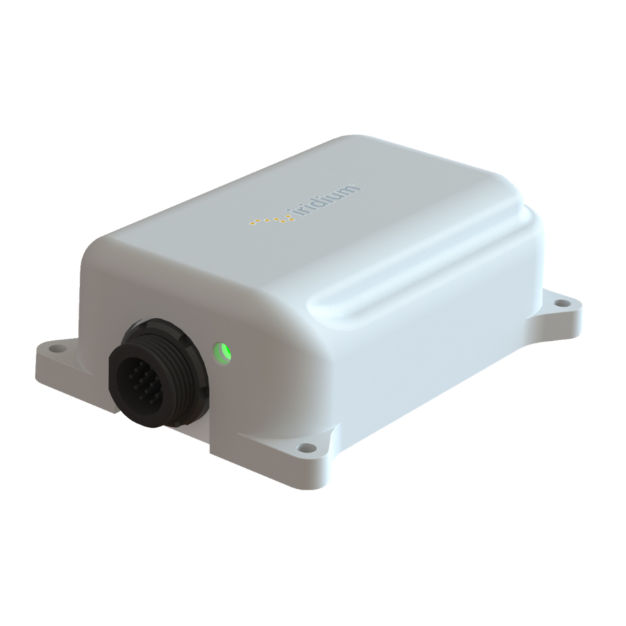
Refer to the Iridium Edge Pro Hardware Developer Guide [Reference 1] for details on the Iridium Edge Pro and its accessories and to the Iridium Edge Pro User Guide [Reference 2] for installation guidelines, safety warnings and regulatory information. -
Page 9: Ac Adaptor With International Plugs
Figure 2-5: AC Adaptor with accessories 1-Meter Mating Cable The 1-Meter Mating Cable provides a connection between the Iridium Edge Pro and the Test Interface Card. The 1-Meter Mating Cable supports a USB connection and its short length makes it useful for lab testing. -
Page 10: 10-Meter Mating Cable
The 10-Meter Mating Cable, as shown in Figure 2-7, provides a connection between the Iridium Edge Pro device and the Test Interface Card. The 10-Meter Mating Cable is useful for field testing when the Iridium Edge Pro needs to be mounted and installed at a distance from the TIC. -
Page 11: Field Installable Connectors
Figure 2-7: 10-Meter Mating Cable Field Installable Connectors The Field Installable Connectors, as shown in Figure 2-8, are provided in the kit to allow Iridium VARs to create custom cables for testing purposes. Refer to the Iridium Edge Pro Hardware Developer Guide [Reference 1] for more details on this connector and for guidelines on making cables using this connector. -
Page 12: Automotive Power Adaptor
The cable has a black ground and a red power 18 AWG wires. This cable is around 2 meters long and is shown in Figure 2-10. Figure 2-10: Iridium Edge Pro Development Kit bare power cable Controlled for export under the EAR. See front cover for use and disclosure statement. -
Page 13: Micro Usb Cable
The Serial DB09 cable can be used to connect to third party RS-232 devices that need to connect to an application developed for the Iridium Edge Pro. Alternatively, it can be used to connect the Iridium Edge Pro’s RS-232 port to a PC when used with the Serial to USB Converter. -
Page 14: Serial To Usb Converter
2.11 Serial to USB Converter The Serial to USB Converter is provided for applications that need to connect the Iridium Edge Pro’s RS-232 port to a PC’s USB port. The Serial to USB Converter is shown in Figure 2-13. Figure 2-13: Iridium Edge Pro Development Kit USB to serial cable Controlled for export under the EAR. -
Page 15: Setting Up The Hardware
The 10-Meter Mating Cable is provided to support field testing and development where the Iridium Edge Pro is located at a distance from the TIC. This configuration is only required once the Iridium Controlled for export under the EAR. See front cover for use and disclosure statement. -
Page 16: Powering The Tic And Edge Pro
Iridium Edge Pro (see Figure 3-2). Both connectors are keyed. When connecting the cable to either the TIC or the Iridium Edge Pro, secure both connections by pushing the connectors in and then twisting the lock-rings in a clockwise motion (by hand, no tools necessary). - Page 17 TIC turn on as per Figure 3-5. Controlled for export under the EAR. See front cover for use and disclosure statement. Iridium Satellite LLC Proprietary and Confidential Information CD-200134-00 Iridium Edge Pro Development Kit Guide v2.0 Page 17 of 26...
-
Page 18: Connecting The Tic To Pc
The USB port is recommended for initial setup and debug. Connect to the USB port using the Micro USB adaptor cable as per Figure 3-6. Whenever using the Micro USB adaptor cable to connect to the PC, the 1-Meter Mating Cable must be used to connect to the Iridium Edge Pro as per section 3.1. -
Page 19: Connecting To The Pc
Figure 3-7: USB’s connection with green LED Controlled for export under the EAR. See front cover for use and disclosure statement. Iridium Satellite LLC Proprietary and Confidential Information CD-200134-00 Iridium Edge Pro Development Kit Guide v2.0 Page 19 of 26... - Page 20 Figure 3-8. Figure 3-8: Completed hardware setup Controlled for export under the EAR. See front cover for use and disclosure statement. Iridium Satellite LLC Proprietary and Confidential Information CD-200134-00 Iridium Edge Pro Development Kit Guide v2.0 Page 20 of 26...
-
Page 21: Test Interface Card
Test Interface Card Base Flex Connector Board Assembly (includes panel mount connector) Figure 4-1: Test Interface Card Assembly The TIC has the following interfaces that can be used to test and power the Iridium Edge Pro Power System • •... - Page 22 4-position screwless, spring loaded terminal block. The terminal block supports 20-26 AWG wire. Alternate Power Input allows the Iridium Edge Pro to be powered directly from an external source independent from the TIC’s power supply on Main Power Input. Alternate Power Input is useful for test setups such as measuring Iridium Edge Pro device's power consumption.
-
Page 23: Usb
LEDs blink green momentarily. By default, the Iridium Edge Pro device's RS-232 port is set to “auto detect”. With auto detect a valid RS-232 receive input is required before the RS-232 transmitter is activated. The presence LED can be used to show if a valid RS-232 signal is present. -
Page 24: Can Bus
The interface, labelled as CAN BUS, reference designator J12 on the TIC) is a 4-position screwless, spring loaded terminal block, as shown in Figure 4-6. The terminal block can be used with 20-26 AWG wire and provides a direct connection to the Iridium Edge Pro CAN Bus signals. Figure 4-6: CAN Bus Interface... - Page 25 4.6.1 Local I/O Testing The Iridium Edge Pro’s I/Os can be tested directly using the TIC when I/O is set to LOCAL. In this case, the yellow LED is on when the I/O line is high and off when floating or ground.
- Page 26 IN/OUT switches. When the I/Os are configured as outputs, the orange LED turns on when the I/O pin is pulled low. Controlled for export under the EAR. See front cover for use and disclosure statement. Iridium Satellite LLC Proprietary and Confidential Information CD-200134-00 Iridium Edge Pro Development Kit Guide v2.0 Page 26 of 26...