
Related Manuals for Agilent Technologies 8757D


Summary of Contents for Agilent Technologies 8757D
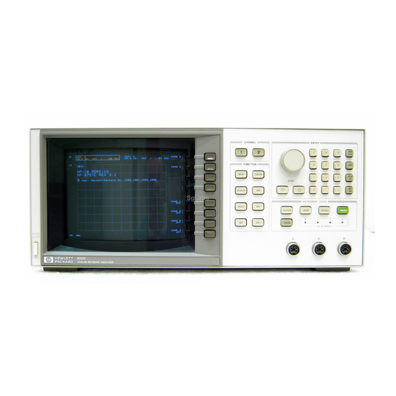
- Page 1 Installation Note 8757D/E CRT to LCD Upgrade Kit Part Number 08757-60159 Agilent Part Number: 08757-90195 Printed in USA June 2003 © Copyright 2003 Agilent Technologies, Inc. All rights reserved.
- Page 2 Notice THE MATERIAL CONTAINED IN THIS DOCUMENT IS PROVIDED “AS IS,” AND IS SUBJECT TO BEING CHANGED, WITHOUT NOTICE, IN FUTURE EDITIONS. FURTHER, TO THE MAXIMUM EXTENT PERMITTED BY APPLICABLE LAW, AGILENT DISCLAIMS ALL WARRANTIES, EITHER EXPRESS OR IMPLIED WITH REGARD TO THIS MANUAL AND ANY INFORMATION CONTAINED HEREIN, INCLUDING BUT NOT LIMITED TO THE IMPLIED WARRANTIES OF MERCHANTABILITY AND FITNESS FOR A PARTICULAR PURPOSE.
- Page 3 This upgrade kit replaces the cathode ray tube (CRT) with a liquid crystal display (LCD). About the Upgrade Kit Products affected: ..... 8757D and all options 8757E and all options Installation to be performed by: .
- Page 4 Keypad board 08757-60149 LCD assembly 08757-60151 Rear panel assembly 08757-60153 Front panel overlay Option 012 08757-80083 Front panel overlay 8757D Standard 08757-80084 Front panel overlay Option 001 08757-80085 Front panel overlay Option 002 08757-80086 ON/OFF overlay 08757-80098 Name plate (Agilent Technologies)
- Page 5 Table 1 Upgrade Kit Contents (08757-60159) Description Part Number Screw (SMM4.0 10 CWPNTX) 0515-0380 Screw (SMM3.0 6 CWPNTX) 0515-0430 Screw (SMM3.5 6 PCFLTX) 0515-1382 Screw (SMM5.0 10 PCFLTX) 0515-1384 Screw (SMM3.0 20 CWPNTX) 0515-1410 Screw (SMM4.0 7 PCFLTX) 0515-2086 Screw (SMM3.5 8 PCPNTX) 0515-1402 Cable clamp (rear frame) 1400-0017...
-
Page 6: Electrostatic Discharge Protection
Installation Procedure for the Upgrade Kit The network analyzer must be in proper working condition prior to installing this option. Any necessary repairs must be made before proceeding with this installation. The servicing instructions are for use by qualified personnel only. To WARNING avoid electrical shock, do not perform any servicing unless you are qualified to do so. -
Page 7: Overview Of The Installation Procedure
Overview of the Installation Procedure 1. Remove the outside covers. 2. Remove the inside covers. 3. Remove the front panel. 4. Remove the CRT. 5. Remove the rear panel. 6. Remove the power supply board. 7. Remove the front frame. 8. -
Page 8: Equipment And Tools Required
Equipment and Tools Required Table 2 Required Equipment and Tools Description Part Number T-10 TORX driver (set to 10 in-lbs) T-15 TORX driver (set to 21 in-lbs) 15/64 open-end wrench Hex screwdriver (5.5 mm) Flatblade screwdriver (small) Needle-nose pliers ESD grounding wrist strap 9300-1367 5 ft grounding cord for wrist strap 9300-0980... - Page 9 Step 1. Remove the Outside Covers The opening of covers or removal of parts is likely to expose WARNING dangerous voltages. Disconnect the product from all voltage sources while it is being opened. Refer to Figure 1-2. 1. Disconnect the power cord. 2.
- Page 10 Step 2. Remove the Inside Covers Refer to Figure 2-1. 1. Remove the logger cover by removing two screws (item 2. Remove the CRT cover by removing twelve screws: • five screws (item ) (Two of these screws do not hold the cover in place, but need to be removed.) •...
-
Page 11: Step 3. Remove The Front Panel
Step 3. Remove the Front Panel Refer to Figure 3-1. 1. Turn the instrument over to expose the bottom side of the instrument. 2. Disconnect the detector connections (J2, J3, J4, and J5) from the motherboard. (There may be three or four depending on the option configuration.) Figure 3-1 Detector Connectors 08757-90195... - Page 12 Refer to Figure 3-2. 3. Turn the instrument over to expose the top side of the instrument. 4. Remove the softkey cover (item ). Gently lift the softkey cover off using something such as a flatblade screwdriver. 5. Remove the bezel by removing the two screws underneath the softkey cover. 6.
- Page 13 Option 002 has a gray RF cable that connects the keypad assembly to NOTE connector J1 on the CAL/MOD driver board (green guides). Lift the board slightly and use a 15/64 open-end wrench to disconnect the cable. Refer to Figure 3-3.
- Page 14 Step 4. Remove the CRT Recycle or dispose of the cathode ray tube (CRT) in accordance with NOTE applicable environmental laws. Refer to Figure 4-1. 1. Remove the connector clip from connector J4 and unplug the large ribbon cable (item 2.
- Page 15 7. Disconnect the white cable (item ) from connector J2 by lifting the CAL/MOD driver board. Mark the log amplifier boards (08757-60087) and the corresponding white CAUTION board tab so that their placement order is uniquely identified. (Use a permanent marker). It will be necessary to replace each board in their original slot during the installation procedure.
-
Page 16: Step 5. Remove The Rear Panel
Step 5. Remove the Rear Panel Refer to Figure 5-1. 1. Turn the instrument over to expose the bottom side of the instrument. 2. Disconnect the thermistor switch by removing two screws (item 3. Cut the two tie wraps that bundle the blue and red cables, and the gray and white/gray cables (item 4. - Page 17 Refer to Figure 5-2. 7. Remove the four bottom and two top rear panel screws (item ) and tip the rear panel partially out of the frame. 8. Disconnect the large gray ribbon cable (item ) from the motherboard. The rear panel is now free from the analyzer.
-
Page 18: Remove The Power Supply Board
Step 6. Remove the Power Supply Board Refer to Figure 6-1. 1. Remove the plastic warning shield on the power supply board. Using needle-nose pliers, pinch and hold the protruding plastic sleeve (item ) while lifting the plastic shield off the board. - Page 19 Refer to Figure 6-2. 2. Remove the power supply board by removing nine screws (item ). Use the plastic ring (item ) to help lift the board. You may encounter resistance as you are removing the board due to the length of the pins on connector J2. Figure 6-2 Power Supply Board (top view) 08757-90195...
- Page 20 Step 7. Remove the Front Frame Refer to Figure 7-1. 1. Remove the ON/OFF switch plate by removing three screws (item 2. Remove the front frame by removing eight screws (item ): four on each side of the instrument frame. Figure 7-1 Front Frame 08757-90195...
- Page 21 Refer to Figure 7-2. 3. Remove the ON/OFF switch guide along with the actuator rod by unhooking the spring (item ) using needle-nose pliers. Once the switch guide is removed, pull the actuator rod off of the switch guide. Figure 7-2 ON/OFF Switch 08757-90195...
- Page 22 Step 8. Remove the CRT Shield Refer to Figure 8-1. 1. Remove seven screws (item ) on the bottom side of the CRT shield: • five attaching the graphics board shield to the CRT shield • two attaching the LCD shield to the motherboard Figure 8-1 CRT Shield Removal (bottom) 08757-90195...
- Page 23 Refer to Figure 8-2. 2. Remove four screws (item ) on the inside of the CRT shield. Figure 8-2 CRT Shield Removal (inside) 08757-90195...
- Page 24 Refer to Figure 8-3. 3. Remove six screws (item ) on the main frame and remove the CRT shield. Figure 8-3 CRT Shield Removal (side) The removal portion of this procedure is now complete. 08757-90195...
- Page 25 Step 9. Install the LCD Shield The new parts referenced in the installation procedure are listed in Table NOTE 1, “Upgrade Kit Contents (08757-60159)” on page Refer to Figure 9-1. 1. Peel off the adhesive backing and attach the new actuator clamp (1400-0510) onto the new LCD shield (08757-00072).
- Page 26 Refer to Figure 9-2. 2. Insert the new LCD shield into the mainframe. (The LCD shield fits on top of the rear frame, see Figure 12-3 on page 36.) 3. Line up the holes and insert six screws (0515-0372): • four on the inside of the LCD shield (item •...
- Page 27 Step 10. Install the Front Frame Observe the top and bottom side of the front frame. The top side of the NOTE front frame has two different size holes. The bottom side holes are one size. Refer to Figure 10-1. 1.
- Page 28 Refer to Figure 10-2. 4. Remove the plastic ON/OFF button (item ) from the old switch guide and place it on the new switch guide (08757-40008). 5. Attach a new spring (1460 to the new switch guide (item ). Pinch the end of the -1573) spring closed using needle-nose pliers.
- Page 29 Refer to Figure 10-3. 6. Insert the actuator rod into the switch guide (item 7. Insert the actuator rod into the actuator clamp (item ) through the front of the instrument. Figure 10-3 Actuator Rod 8. Turn the instrument over and attach the spring to the LCD shield (item ).
- Page 30 Refer to Figure 10-4. 9. Place the black actuator extender (item ) on the opposite end of the actuator rod. Using needle-nose pliers, push back on the actuator rod and insert the extender. 10. Press the actuator extender several times to ensure that the switch moves freely. If necessary, use a ftat blade screwdriver to widen the plastic actuator clamp.
- Page 31 Step 11. Install the Power Supply Board Refer to Figure 11-1. 1. Replace fuse F5 (item ) on the power supply board with the 5-amp fuse (2110-0010) provided in the kit. 2. Place the identifying fuse label (9325-5885) over the 4-amp silk screening (item ) on the board.
- Page 32 Refer to Figure 11-2. 3. Add a tie wrap (1400-0249) to secure the new white power cable (08757-60071), (item ). The new power cable contains eight conductors. 4. Connect the new white power supply cable to connector J1 (item ) on the back side of the power supply board.
- Page 33 As you are inserting the power supply board, carefully align the pins on CAUTION connector J2 to the connector on the motherboard. Refer to Figure 11-3. 5. Guide the power cable through the notch opening on the motherboard and insert the power supply board into the instrument.
- Page 34 Step 12. Install the Rear Panel Assembly Refer to Figure 12-1. 1. Place the white cable from the new rear panel assembly (08757-60153) through the rear frame (item ) to the top side of the instrument. Route the cable past the transformer. It will be inserted into the CAL/MOD driver board, green guides, during the installation procedure.
- Page 35 Refer to Figure 12-2. 4. Connect the transformer wires to the line module using needle-nose pliers. Figure 12-2 Line Module Wires 08757-90195...
- Page 36 Refer to Figure 12-3. 5. Insert the new rear panel into the frame. Be sure all wires are clear of the fan and the frame. 6. Insert four screws (0515-0380), (item ). Each will include one of the following: • screw only •...
- Page 37 Step 13. Install the Keypad Board Refer to Figure 13-1. 1. Remove the detector interface connector cables (item ) from the old front panel and place them on the new front sub-panel (08757-00071). Orient the notch, on the black portion of the connectors, down and secure the connectors using hex nut (0535-0031).
- Page 38 Refer to Figure 13-1 on page 7. Connect the RPG cable to J1 (item ) on the keypad board. 8. Pull the RPG cable through the hole on the keypad board and insert the board onto the sub-panel. Position the RPG cable as shown in Figure 13-1 on page 9.
- Page 39 Step 14. Install the Keypad Assembly Refer to Figure 14-1. 1. Connect the large gray ribbon cable to connector J1 (item ) on the motherboard. 2. Connect the detector interface cables (item ) to the motherboard. Refer to “Detector Connectors” on page 11 for a more detailed image.
- Page 40 Step 15. Install the LCD Assembly Refer to Figure 15-1. 1. Attach the new Agilent Technologies name plate (08757-80099) (item ) on the front of the new LCD assembly (08757-60151). 2. Attach the ON/OFF overlay (08757-80098), (item Figure 15-1 Front Panel Label...
- Page 41 Refer to Figure 15-2. 3. Connect the small ribbon cable (item ) from the keypad assembly to the LCD assembly. It is imperative that the correct screws be used to secure the LCD CAUTION assembly. Incorrect screw length may damage the LCD. 4.
- Page 42 Step 16. Install the Display Interface Board Refer to Figure 16-1 on page 1. Place the new display interface board (85101-60293) into the LCD shield and insert eight screws (0515-0430), (item 2. Connect the LCD data cable to connector J6 (item 3.
- Page 43 Figure 16-1 Display Interface Board 08757-90195...
- Page 44 Step 17. Final Button-Up Electrostatic discharge (ESD) can damage or destroy electronic CAUTION components. All work on electronic assemblies should be preformed at a static-safe workstation. Refer to the documentation that pertains to your instrument for information about static-safe workstations and ordering static-safe accessories.
-
Page 45: Step 18. Operator's Check
After upgrading your instrument, complete the following test to verify its performance. 1. Turn the power on. 2. Perform the Operator’s Check. Refer to the Operating Reference 8757D Scalar Network Analyzer (08757-90169) on page A-1. The Operator’s Reference is part of the Operating Manual (08757-90109). - Page 46 08757-90195...