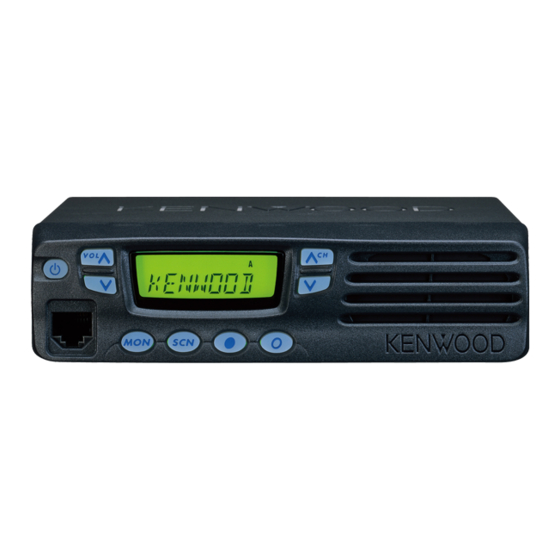
Kenwood TK-8100 Service Manual
Hide thumbs
Also See for TK-8100:
- Service manual (56 pages) ,
- Instruction manual (24 pages) ,
- Specifications (2 pages)
Table of Contents
Advertisement
Quick Links
Document Copyrights
Copyright 2006 by Kenwood Corporation. All rights reserved.
No part of this manual may be reproduced, translated, distributed, or transmitted in any
form or by any means, electronic, mechanical, photocopying, recording, or otherwise, for
any purpose without the prior written permission of Kenwood.
Disclaimer
While every precaution has been taken in the preparation of this manual, Kenwood
assumes no responsibility for errors or omissions. Neither is any liability assumed for
damages resulting from the use of the information contained herein. Kenwood reserves
the right to make changes to any products herein at any time for improvement purposes.
文档版权信息
Kenwood Corporation 拥有版权 2006 。保留所有权利。
未经 Kenwood 公司预先书面同意,无论出于何种目的,均不得以任何形式或任何方式包
括电子、机械、影印、录音或其他方式复制、翻译、分发或传播本手册的任何部分。
免责声明
Kenwood 公司在准备本文档时已采取所有必要的预防措施,恕不对错误或疏漏承担任何
责任,也不对因使用本文中所含的信息而导致的损害负责。 Kenwood 公司保留出于改进
的需要而随时对文中的产品信息做出更改的权利。
Advertisement
Table of Contents

Related Manuals for Kenwood TK-8100


Summary of Contents for Kenwood TK-8100
- Page 1 Kenwood. Disclaimer While every precaution has been taken in the preparation of this manual, Kenwood assumes no responsibility for errors or omissions. Neither is any liability assumed for damages resulting from the use of the information contained herein. Kenwood reserves the right to make changes to any products herein at any time for improvement purposes.
- Page 2 UHF FM TRANSCEIVER / UHF TK-8100 SERVICE MANUAL / C6 version © 2005-10 PRINTED IN JAPAN B51-8739-00 ( N ) 566 Modular jack Key top Panel assy (E08-0877-05) (K29-9262-01) (A62-1074-03) RF coaxial receptacle (M) Chassis (E04-0167-05) (A10-4080-11) Fuse (6x30, 10A)
-
Page 3: Table Of Contents
TK-8100 CONTENTS / GENERAL ..........2 KKKKKKKKKKKKKKKKKKKKKKKKKKKKKKKKKKKKKKKKKKKKKKKKKKKKKKKKKKKKKKKKKKKKKKK O SYSTEM SET-UP ........5 KKKKKKKKKKKKKKKKKKKKKKKKKKKKKKKKKKKKKKKKKKKKKKKKKKKKKKKKKKKKKKKKKKKKKKK R ! KKKKKKKKKKKKKKKKKKKKKKKKKKKKKKKKKKKKKKKKKKKKKKKKKKKKKKKKKKKKKKKKKKKKKKK S OPERATING FEATURES ......6 ! KKKKKKKKKKKKKKKKKKKKKKKKKKKKKKKKKKKKKKKKKKKKKKKKKKKKKKKKKKKKKKKKKKKKKKK T REALIGNMENT ......... 7 INSTALLATION ........18 ==== KKKKKKKKKKKKKKKKKKKKKKKKKKKKKKKKKKKKKKKKKKKKKKKKKKKKKKKKKKKKKKKKKKKKKKKK NU ! KKKKKKKKKKKKKKKKKKKKKKKKKKKKKKKKKKKKKKKKKKKKKKKKKKKKKKKKKKKKKKKKKKKK OM DISASSEMBLY FOR REPAIR ....20 ! KKKKKKKKKKKKKKKKKKKKKKKKKKKKKKKKKKKKKKKKKKKKKKKKKKKKKKKKKKKKKKKKKKKK OP CIRCUIT DESCRIPTION ...... -
Page 4: General
TK-8100 GENERAL / PERSONAL SAFETY !"#$% &'()*+,- The following precautions are recommended for personal !"#$%&'=EMKS= F= !"# $%&'()* safety : !"#$% &'()*+, -./0123() • DO NOT transmit if someone is within two feet (0.6 !"#$%&'()*+,-./01 meter) of the antenna. !"#$ %&'()*+,- ./01 2- 345 •... - Page 5 Control station. The antenna system selection depends on !"#$%&'()*+,%&-./ many factors and is beyond the scope of this manual. Your hbktlla !"#$ KENWOOD dealer can help you select an antenna system that will best serve your particular needs. !" 4-2. Radio location QJOK= !"#$%&'()*+,-.!/01 2/0345...
-
Page 6: System Set-Up
TK-8100 SYSTEM SET-UP / Merchandise received Frequency range (MHz) RF power Type Choose the type of transceiver 350~390 See page 7. Transceiver programming A personal computer (IBM PC or compatible), programming interface (KPG-46), and programming software (KPG-80D) are required for programming. -
Page 7: Operating Features
TK-8100 OPERATING FEATURES / !" NJPK= NJNK= !"# NJOK= !"#$% !"#$%&'=E !"#$%&'()*'(+,-. !"#$%&'()*+,- !"# !"#$%&'()*+,- !"#$%&'() !"#$%&'!"( !"#$%&'()*+, q =E ! "#$% & !"#$% !"#$%&'()$*+,-. w sli= =L= = =E !"#$%&'( !"#$%"#&'() !*+,- !"# !"#$%&'()*'(+,- r `e= =L= = =E !"#$%&'() -
Page 8: Realignment
Self programming mode [MON]+Power ON (Two seconds) xjlkz !" 3. PC Mode 3-1. Preface PJNK= !"#$%&'#( )*+,=EhmdJQSF= The TK-8100 transceiver is programmed using a personal qhJUNMM !" computer, a programming interface (KPG-46) and program- =EhmdJUMaF= !"# $%&'()*+,-N ming software (KPG-80D). !"# The programming software can be used with an IBM PC or compatible. - Page 9 Note : !"#$ Clone mode should be enabled. !"qhJUNMM 1. Turn the master TK-8100 power ON with the [CH DOWN] =x`e=altkz= F =`i !"#$% key held down (2 seconds), “ CLONE ” is displayed on the...
- Page 10 TK-8100 REALIGNMENT / !"# 4-1. Adding the Data Password QJNK= !"# = !"#$%&'( )*+, If the data password is set in the optional feature menu, cmr = !"#$%&'(=E !"#$F you must enter the password (Master transceiver) to activate !"N Q !"...
- Page 11 TK-8100 REALIGNMENT / !"# 5-2. Adding the Data Password RJOK= !"# = !"#$%&'( )*+, If the data password is set in the optional feature menu, cmr = !"#$%&'()*+ you must enter the password to activate a self programming !"N Q !"...
- Page 12 TK-8100 REALIGNMENT / No. Function Choices Display Remarks - - - - - - - - key : Off/QT/DQT lÑÑ - - - - - - - - = W= lÑÑLnqL signaling switching QT 67.0~254.1 6 7 . 0✽ 6 7 . 0✽...
- Page 13 TK-8100 REALIGNMENT / No. Function Choices Display Remarks D Q T 0 0 0 Ι ✽ D Q T 0 0 0 Ι ✽ DQT 000~777 key : Hold 1 second anq=MMMúTTT = W= D Q T 7 7 7 Ι ✽...
- Page 14 TK-8100 REALIGNMENT / ■ Flow Chart 自台编程模式 Self programming mode [MON] [MON] [MON] [MON] Channel Group 信道设置模式 信道选择 组选择 Channel setting mode selection selection [SCN] [SCN] [MON] [MON] Change 更改频率步长 RX频率 RX frequency frequency step Hold [ ] 按住 [ ] [SCN] 或...
- Page 15 TK-8100 REALIGNMENT / 5-4. DTMF Setting Mode RJQK=aqjc !" #$ %&'()*+,-./0123)456 Each transceiver can be setup in its action mode by using the panel keys. !" • Pressing [SCN] when “ SELF ” is displayed, sets the = =pbic= =...
- Page 16 TK-8100 REALIGNMENT / ➎ ➏ 3. Insert the KCT-39 cable ( ) into the chassis ( ). The 6. Accessory Connection Cable (KCT-39) ➐ wire harness band ( ) must be inside the chassis and The KCT-39 is an accessory connection cable for connect- face down.
- Page 17 TK-8100 REALIGNMENT / ■ Accessory Port Function / !"# 5. Connect the KCT-39 to the external accessory by inserting ➒ ➓ the crimp terminal ( ) into the square plug ( ), both of which are supplied with the KCT-39.
- Page 18 TK-8100 REALIGNMENT / 7-3. Modifying the Transceiver 7. Ignition Sense Cable (KCT-18) Modify the transceiver as follows to turn the power on and The KCT-18 is an optional cable for enabling the ignition off with the ignition key. function. The ignition function lets you turn the power to the transceiver on and off with the car ignition key.
-
Page 19: Installation
TK-8100 INSTALLATION / 1. Optional Board !"#$%& 1-1. Voice Scrambler Board Connection NJNK= ■ Modification !"#$%&'$()*+,- 1. Remove the cabinet and shielding cover from the trans- !oOMO oOST ceiver. quJou 2. Delete R202 and R267 on the TX-RX unit. TX-RX UNIT... - Page 20 TK-8100 INSTALLATION / ■ Pins Connection !" !" Voice scrambler 12 pins lead wire 11 pins lead wire functions with connector (A) with connector (B) A-12 – ^JNO A-11 – ^JNN A-10 – ^JNM – – – – – –...
-
Page 21: Disassembly For Repair
TK-8100 DISASSEMBLY FOR REPAIR / 1. When you remove the panel, turn the transceiver up side 4-1. Remove the display unit down. Detach the panel by lifting the tabs as shown be- To remove the display unit from the panel, follow the cor- low. - Page 22 TK-8100 DISASSEMBLY FOR REPAIR / 4-2. Mount the display unit To mount the display unit on the panel, follow the correct Open the top of display procedures shown to ensure easy display unit assembly unit at No. 4 as indicated.
- Page 23 TK-8100 DISASSEMBLY FOR REPAIR / Snap in top of display unit (No. 4). 咬接显示单元顶部 (编号4)。 Snap in bottom of display unit (No. 3). 咬接显示单元底部 (编号3)。 Ensure that display unit holes locator is properly located on the illumination guide locators as shown.
-
Page 24: Circuit Description
TK-8100 CIRCUIT DESCRIPTION / Frequency Configuration !"#$%&'()*+,-./&0QVKVRjeò The receiver utilizes double conversion. The first IF is !QRMâeò !"#$%&'()*+,-. 49.95MHz and the second IF is 450kHz. The first local oscil- !"#$%&'()*+,-./012N !" lator signal is supplied from the PLL circuit. The PLL circuit in the transmitter generates the necessary frequencies. - Page 25 TK-8100 CIRCUIT DESCRIPTION / ■ IF Amplifier Circuit !"#$% !"#$%nPRN ! "#$%f`PMN=E !" The first IF signal is amplified by Q351, and the enters !"#f`PMN !"#$%&'()*QRMâeò IC301 (FM processing IC). The signal is heterodyned again !"#$ !"#%&'()*+,QRMâeò with a second local oscillator signal within IC301 to create a !"#$%&'()*...
- Page 26 TK-8100 CIRCUIT DESCRIPTION / ■ Wide/Narrow Switching Circuit !"#$% !"#$ The Wide port (pin 65) and Narrow port (pin 64) of the CPU SRF= SQF= !"#$%&'()*+,- ./012p t is used to switch between ceramic filters. When the Wide !"#$%&' port is high, the ceramic filter SW diodes (D303, D302) cause EaPMP aPMOF= `cPMN !"#$%&' ()*+,pt...
- Page 27 TK-8100 CIRCUIT DESCRIPTION / !"#$% PLL Frequency Synthesizer !"#$%&'()*+,-./0123(345 The PLL circuit generates the first local oscillator signal for reception and the RF signal for transmission. ■ PLL !"# !"#$%&'(R SKORâeò NSKUjeò !" The frequency step of the PLL circuit is 5 or 6.25kHz. A !"#$%&'(...
- Page 28 TK-8100 CIRCUIT DESCRIPTION / !" Transmitter System ■ Outline !"#$%&'()*+,-./0123456, The transmitter circuit produces and amplifies the desired !"#$%&'()*+ frequency directly. It FM-modulates the carrier signal by means of a varicap diode. ■ Power Amplifier Circuit !"#$% !"#$%&'()*+,'(L !"#$ The transmit output signal from the VCO passes through !"#$=EnRMM nRMN nRMOF=...
- Page 29 TK-8100 CIRCUIT DESCRIPTION / Control Circuit !"#$ The CPU carries out the following tasks: ! "! #$=L !" 1) Controls the WIDE, NARROW, TX/RX outputs. !"#$%&'()* 2) Adjusts the AF signal level of the AF filter (IC251) and =Ef`ORNF= ^c !"...
- Page 30 TK-8100 CIRCUIT DESCRIPTION / ■ Key Matrix Circuit !"#$ !"#$%&'()*+&,-./012 The TK-8100 front panel has function keys. Each of them qhJUNMM !"#$%&'()hjfN hjfQ is connected to a cross point of a matrix of the KMI1 to KMO2 hjfN hjlO !"#$%& hjlN hjlO !"#$%&...
- Page 31 TK-8100 CIRCUIT DESCRIPTION / ■ D/A Converter !=Ef`NSNF= The D/A converter (IC161) is used to adjust MO modula- !"m`=mltbo=`lkqoli tion, AF volume, TV voltage, FC reference voltage, and PC !"#$%&!'(!)*+,-./012 POWER CONTROL voltage level. !"#$%&'( Adjustment values are sent from the CPU as serial data.
-
Page 32: Semiconductor Data
TK-8100 !" SEMICONDUCTOR DATA / ! : 30622MAA-B96GU (TX-RX Unit IC101) Microprocessor / ■ Terminal Function Pin No. Name Function QT/DQT QT/DQT output nqLanq nqLanq DTMF/MSK DTMF/MSK/BEEP output aqjcLjph aqjcLjphL_bbm PLLE PLL IC chip select miib CNVSS CNVss for flash `kspp `ksëë... - Page 33 TK-8100 !" SEMICONDUCTOR DATA / Pin No. Name Function !" Speaker mute !"# AMPSW AF AMP switch ^jmpt Common data Common clock 55,56 RR RS 57~59 DST1~DST3 Destination 1~3 RTúRV apqN apqP NARROW k^oolt WIDE tfab 66~68 SS SU k`...
-
Page 34: Components Description
TK-8100 COMPONENTS DESCRIPTION / !=EuRQJPQPMJOMF Display Unit (X54-3430-20) Ref. No. Parts name Description LCD controller !"# Transistor DC switch Transistor LCD backlit switch !"# Transistor Key backlit switch !"#$ Transistor Dimmer function switch !" D2~5 Key & LCD backlit aO R !"#... - Page 35 TK-8100 COMPONENTS DESCRIPTION / Ref. No. Parts name Description !"L Q251 Transistor Buffer amplifier / RX audio nORN !" Q252,253 FET AF mute / Active while AFM is H nORO ORP L ^cj e !" Q254 Digital transistor AF mute / Active while SPM is H...
-
Page 36: Parts List
Parts without Parts No. are not supplied. Les articles non mentionnes dans le Parts No. ne sont pas fournis. Teile ohne Parts No. werden nicht geliefert. TK-8100 (Y51-4973-01) DISPLAY UNIT (X54-3430-20) TX-RX UNIT (X57-6923-03) Desti- Desti- Ref. - Page 37 TK-8100 PARTS LIST / TX-RX UNIT (X57-6923-03) Desti- Desti- Ref. No. Address Parts No. Description Ref. No. Address Parts No. Description parts nation parts nation CK73GB1H471K CHIP C 470PF C270 C92-0507-05 CHIP-TAN 4.7UF 6.3WV CK73GB1H471K CHIP C 470PF C271 CK73GB1H332K...
- Page 38 TK-8100 PARTS LIST / TX-RX UNIT (X57-6923-03) Desti- Desti- Ref. No. Address Parts No. Description Ref. No. Address Parts No. Description parts nation parts nation C388 CC73GCH1H070B CHIP C 7.0PF C531 C92-0543-05 CHIP-TAN 3.3UF 10WV C389 CK73GB1H103K CHIP C 0.010UF...
- Page 39 TK-8100 PARTS LIST / TX-RX UNIT (X57-6923-03) Desti- Desti- Ref. No. Address Parts No. Description Ref. No. Address Parts No. Description parts nation parts nation L416,417 L92-0443-05 CHIP FERRITE R122,123 RK73GB2A000J CHIP R 1/10W L418 L41-2775-06 SMALL FIXED INDUCTOR (27NH)
- Page 40 TK-8100 PARTS LIST / TX-RX UNIT (X57-6923-03) Desti- Desti- Ref. No. Address Parts No. Description Ref. No. Address Parts No. Description parts nation parts nation R272 RK73GB2A152J CHIP R 1.5K 1/10W R409 RK73GB2A104J CHIP R 100K 1/10W R273 RK73GB2A472J CHIP R 4.7K...
- Page 41 TK-8100 PARTS LIST / TX-RX UNIT (X57-6923-03) Desti- Desti- Ref. No. Address Parts No. Description Ref. No. Address Parts No. Description parts nation parts nation R539 RK73RB2H101J CHIP R 1/2W Q301 2SC2412K TRANSISTOR R601,602 RK73GB2A103J CHIP R 1/10W Q302 2SC4649(N,P)
-
Page 42: Exploded View
TK-8100 !" EXPLODED VIEW / A M3 x 8 : N67-3008-46 B M2.6 x 6 (Br-Tap) : N87-2606-46 C M2.6 x 14 (Br-Tap) : N87-2614-46 Note: If a part reference number is listed in a box on the exploded view of the PCB (for example, Q31), that part does not come with the PCB. -
Page 43: Packing
TK-8100 PACKING / 7 Instruction manual (B62-1879-00) 39 Polystyrene foamed fixture (H10-6636-13) 704 Protection bag 23 Fuse (6x30, 10A) (F51-0016-15) x 2 40 Polystyrene foamed fixture (H10-6639-03) 43 Item carton case (H52-1700-12) KMB-19 (Option installation kit) Protection bag (H25-0103-04) DC cord... -
Page 44: Adjustment
TK-8100 ADJUSTMENT Test Equipment Required for Alignment Test Equipment Major Specifications 1. Standard Signal Generator Frequency Range 350 to 390MHz (SSG) Modulation Frequency modulation and external modulation Output –127dBm/0.1µV to greater than –7dBm/100mV 2. Power Meter Input Impedance 50Ω Operation Frequency... - Page 45 TK-8100 !"#$ %&'( !"#$=EppdF PRM PVMjeò !" # !TÇ_ãLNMMãs JNOTÇ_ãLMKNµs RMΩ PRM PVMjeò NMMt PRM PVMjeò !"=EasjF Ns OMs !"#$%&'()* PMjeò !"#$%& NMeò NMMMjeò !" MKOééã !"=E^c=sqsjF RMeò NMâeò Nãs Ps !"=E^dF OMeò OMâeò M Ns !" Nâeò P RMãs NMsêãë...
- Page 46 TK-8100 ADJUSTMENT / • AF PA IC (IC252) Adjustment Location / How to mounting the IC252. ■ Switch / !"#=Ef`OROF Power Display !" f`ORO 电源 显示 Volume Channel up/down up/down Speaker 音量高/低 信道上/下 扬声器 Pin 1 marker TX-RX unit Component side...
- Page 47 TK-8100 ADJUSTMENT PCB Section Measurement Adjustment Specifications/ Item Condition Test equipment Terminal Parts Method Remarks 1. Setting 1) Power supply voltage DC Power supply terminal : 13.6V ± 0.1V 2. VCO lock 1) CH : TX high Digital voltmeter TC402 5.5V...
- Page 48 TK-8100 !"#$NPKSs ! NF `e !"# !" q`QMO RKRs MKNs !"# OF `e q`QMN RKRs MKNs !"# PF `e MKTs !"# QF `e MKRs !"=E F PK fc=Åçáä iPMN PKOR PKPRs=Ea`F !"#$%& !" JRPÇ_ã=ERMNµsF Nâeò Pâeò !"#=E F !" QK oc...
- Page 49 TK-8100 ADJUSTMENT Measurement Adjustment Specifications/ Item Condition Test equipment Terminal Parts Method Remarks 3. Squelch 1 1) CH : RX low (Wide) PC key Adjust to open the squelch CH : RX center (Wide/Narrow) CH : RX high (Wide) 2) SSG output : –120dBm (0.22µV) (Wide)
- Page 50 TK-8100 ! NF `e !"=E F !"#$ !"#=E L F !"=E F !"#$%& NOMÇ_ã=EMKOOµsF=E F NNVÇ_ã=EMKORµsF=E F Nâeò PKMâeò=E F NKRâeò=E F !"# !" !"# NF `e NMMeò ! NF `e !" eÉñ=Ç~í~=ORR !" NF `e NKMt !"# !"# !"# !"...
-
Page 51: Terminal Function
TK-8100 TERMINAL FUNCTION ■ Function Port Assignment Name Function KDS-100, KGP-2A/2B Data Name Clock FNC1 Chip enable FNC2 FNC3 Data Channel Switched B FNC4 KMO2 Key matrix output 2 FNC5 Carrier Operated Relay KMI4 Key matrix input 4 FNC6 Audio Mute... - Page 52 TK-8100 !"#$ kçK hapJNMMI=hdmJO^LO_ ck`N ck`O ck`P ck`Q !"# hjlO ck`R hjfQ ck`S !" hjlN ck`T hjfP ck`U hjfN !"#$ hjfO ck`N ellh Loua ck`O ck`P mltbo ck`Q !"N=ENF ck`R !"O=EOF mqqLqua ck`S !"P=EQF ck`T !"Q=EUF ck`U !"#$%&'(E !"#$F kçK kçK...
-
Page 53: Display Unit (X54-3430-20)
TK-8100 板 PC BOARD / PC DISPLAY UNIT (X54-3430-20) Component side view (J72-0885-09) VOL UP POWER VOL DN DISPLAY UNIT (X54-3430-20) Foil side view (J72-0885-09) HOOK... - Page 54 TK-8100 板 PC BOARD / PC DISPLAY UNIT (X54-3430-20) Component side view (J72-0885-09) J72-0885-09 Ref. No. Address Ref. No. Address CH UP CH DN Component side Layer 1 Layer 2 Foil side DISPLAY UNIT (X54-3430-20) Foil side view (J72-0885-09) Ref. No. Address Ref.
- Page 55 TK-8100 TK-8100 板 板 PC BOARD / PC PC BOARD / PC DISPLAY UNIT (X54-3430-20) Component side view (J72-0885-09) DISPLAY UNIT (X54-3430-20) Component side view (J72-0885-09) J72-0885-09 Ref. No. Address Ref. No. Address VOL UP CH UP POWER VOL DN...
- Page 56 TK-8100 板 PC BOARD / PC TX-RX UNIT (X57-6923-03) Component side view (J79-0030-09) EXT. SP R272 D251 C272 R274 R275 R273 C271 TEMP2 CNVSS IC252 R101 R271 C276 POWER C270 R270 RESET Q254 R267 R223 R202 R277 DETO2 R105 R151...
- Page 57 TK-8100 板 PC BOARD / PC TX-RX UNIT (X57-6923-03) Component side view (J79-0030-09) IC502 C611 C612 C605 C603 C604 D608 R605 D606 C614 C573 R606 TEMP1 R532 L505 R531 R380 R528 C391 C559 C539 R527 R538 C538 C527 R221 C220...
-
Page 58: Tx-Rx Unit (X57-6923-03)
TK-8100 TK-8100 板 板 PC BOARD / PC PC BOARD / PC TX-RX UNIT (X57-6923-03) TX-RX UNIT (X57-6923-03) Component side view (J79-0030-09) Component side view (J79-0030-09) EXT. SP IC502 C611 C612 C605 C603 C604 D608 R605 D606 C614 C573 R606... - Page 59 TK-8100 板 PC BOARD / PC TX-RX UNIT (X57-6923-03) Foil side view (J79-0030-09) R800 L603 D605 C601 C606 D604 L601 L361 C390 C537 C385 D354 C387 D355 L359 C389 CN301 CN503 C382 C383 D353 R374 C370 C501 C379 TC353 R359...
- Page 60 TK-8100 板 PC BOARD / PC TX-RX UNIT (X57-6923-03) Foil side view (J79-0030-09) C283 R281 R535 R526 C531 R524 C523 CN502 CN501 C516 L504 R523 R517 R520 Q502 R103 R102 C520 C540 C279 D502 R131 R130 C104 R129 C431 D404...
- Page 61 TK-8100 TK-8100 板 板 PC BOARD / PC PC BOARD / PC TX-RX UNIT (X57-6923-03) TX-RX UNIT (X57-6923-03) Foil side view (J79-0030-09) Foil side view (J79-0030-09) C283 R281 R800 L603 D605 C601 C606 D604 L601 L361 C390 R535 R526 C537...
-
Page 62: Schematic Diagram
TK-8100 SCHEMATIC DIAGRAM / TX-RX UNIT (X57-6923-03) D403,404 RX VCO C430 Q402,403 RX VCO R:6.6V R:1.0V CHARGE PUMP Q405 L406 D404 C426 L408 2SK508NV(K52) C432 R403 R414 R402 270n MA2S304 0.5p VOTAGE R401 DROPPED D402 R410 Q402 HZU5ALL R418 R419... - Page 63 TK-8100 SCHEMATIC DIAGRAM / TX-RX UNIT (X57-6923-03) PRE DRIVE AMP T:6.0V PRE DRIVE AMP 6.1V Q502 RF AMP T:5.6V T:6.8V T:1.10V T:7.3V T:0.29V RF SWITCH 4.87V Q500 Q501 2SC3357-A C523 BUFFER AMP 7.2V Q411 C502 2SC5108(Y)F C509 2SC3357-A C516 1.51V...
- Page 64 TK-8100 SCHEMATIC DIAGRAM / IC502 POWER MODULE RA30H3340M TX-RX UNIT (X57-6923-03) C609 C612 R800 R92-1061-05 ANT SW 1.5p D602 R538 MA4PH633 C602 L602 L603 T:12.9V 1000p 1.5T 1.5T T:0.99V D606,607 APC VOLTAGE D1-3 DETECT SURGE ABSORPTION VOLTAGE PROTECTION D607 D606...
- Page 65 TK-8100 SCHEMATIC DIAGRAM / DISPLAY UNIT (X54-3430-20) E08-0877-05 HOOK SURGE ABSORPTION DA221 R90-0724-05 E40-6005-05 POWER SWITCH POWER HOOK KMI2 KMI1 COM2 SEG20 KMI3 COM3 SEG19 KMO1 SEG18 4.9V KMI4 VLCD SEG17 KMO2 SEG16 VLCD1 LCD CONTROLLER VLCD2 SEG15 LC75834W SEG14...
- Page 66 TX-RX UNIT (X57-6923-03) DISPLAY UNIT (X54-3430-20) IC502 PRE DRIVE AMP T:6.0V POWER MODULE D403,404 6.1V PRE DRIVE AMP Q502 RA30H3340M RX VCO C430 RF AMP 4.87V RF SWITCH T:5.6V Q500 T:6.8V T:1.10V Q501 T:7.3V T:0.29V 2SC3357-A Q402,403 RX VCO BUFFER AMP 7.2V C523 R:6.6V...
-
Page 67: Block Diagram
TK-8100 BLOCK DIAGRAM / DISPLAY UNIT X54-3430-20 TX-RX UNIT X57-6923-03 Q404 2SC4649(N,P) POWER FNC1~FNC8 2SK508 Q402 IC401 2SA1832(GR)F PTT(TXD) CHARGE MB15A02 PUMP PLLE HOOK(RXD) LOOP Q407 DATAI PLL IC FILTER 2SJ243 DETO TXAFI 16.8MHz CHARGE KMO1 TXAFO PUMP 16.8MHz Q403... - Page 68 TK-8100 BLOCK DIAGRAM / IC502 RA30H3340M POWER MODULE Q501 Q502 D602 Q405 Q410 Q411 Q500 2SC3357-A 2SK3357-A MA4PH633 2SK508NV(K52) 2SC5108(Y)F 2SC5108(Y)F 2SC5108(Y)F DRIVE BUFF DRIVE ANT SW Q408 D409 Q407 KRX102U DAN235E 2SJ243 D606 POW. D607 POW. MA742 MA742 TXRX Q302 16.8MHz...
-
Page 69: Level Diagram
TK-8100 LEVEL DIAGRAM / Receiver Section / Center Frequency 49.95MHz 450kHz W : –85.0dBm N : –80.5dBm W : –121.0dBm W : –119.0dBm W : –105.5dBm W : –106.0dBm W : –117.5dBm W : –103.0dBm N : –120.5dBm N : –118.5dBm N : –105.5dBm... - Page 70 TK-8100 LEVEL DIAGRAM / Audio Frequency 450kHz W : –93.0dBm N : –91.0dBm /CF2 0.34Vrms 0.33Vrms 0.27Vrms 0.31Vrms 0.33Vrms 10mVrms 0.55Vrms 0.45Vrms IC301 IC251 IC251 IC251 IC251 IC161 IC252 Q251 vel meter. 2dB SINAD.) To make measurements in the AF section, connect the AC level meter.
-
Page 71: Specification
TK-8100 SPECIFICATIONS GENERAL Frequency Range ........... 350 to 390MHz Channels / Groups .......... 64CH / 8GRP Channel Spacing ..........Wide : 25kHz Narrow : 12.5kHz PLL Channel Stepping ........5.0, 6.25kHz Operating Voltage ........... 13.6V DC ± 15% Current Drain ..........Less than 0.4A on standby Less than 1.0A on receive... - Page 72 TK-8100 ! KKKKKKKKKKKKKKKKKKKKKKKKKKKKKKKKKKKKKKKKKKKKKKKKKKKKKKKKKKK PRM PVMjeò KKKKKKKKKKKKKKKKKKKKKKKKKKKKKKKKKKKKKKKKKKKKKKKKKKKKK SQ ! KKKKKKKKKKKKKKKKKKKKKKKKKKKKKKKKKKKKKKKKKKKKKKKKKKKKKKKKKKK ORâeò NOKRâeò !"#$%& KKKKKKKKKKKKKKKKKKKKKKKKKKKKKKKKKKKKKKKK R SKORâeò ! KKKKKKKKKKKKKKKKKKKKKKKKKKKKKKKKKKKKKKKKKKKKKKKKKKKKKKKKKKK NPKSs ! KKKKKKKKKKKKKKKKKKKKKKKKKKKKKKKKKKKKKKKKKKKKKKKKKKKKKKKKKKK !"#MKQ^ !"#NKM^ !"#UKM^ !"# KKKKKKKKKKKKKKKKKKKKKKKKKKKKKKKKKKKKKKKKKKKKKKKKKKK !" KKKKKKKKKKKKKKKKKKKKKKKKKKKKKKKKKKKKKKKKKKKKKKKKKKKKKKK NSM=E F QP=E F NMT=E F= = NKMâÖ !"# KKKKKKKKKKKKKKKKKKKKKKKKKKKKKKKKKKKKKKKKKKKKKKKKKKK QMjeò bf^Lqf^JSMP =ENOÇ_=pfk^aF KKKKKKKKKKKKKKKKKKKKKKKKKKKKKKKKKKKKKKK MKOUµs...
- Page 73 13, Boulevard Ney, 75018 Paris, France Unit 3712-3724, Level 37, Tower one Metroplaza, 223 Hing Fong Road, Kwai Fong, N.T., Hong Kong KENWOOD House, Dwight Road, Watford, Herts., WD18 9EB United Kingdom 1 Ang Mo Kio Street 63, Singapore 569110...