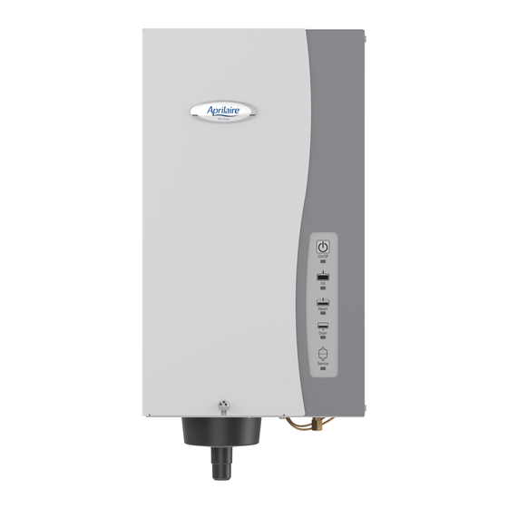
Aprilaire 800 Series Troubleshooting Manual
Single pcb for steam humidifier
Hide thumbs
Also See for 800 Series:
- User manual ,
- Installation & maintenance instructions manual (64 pages) ,
- Owner's manual (32 pages)
Advertisement
Quick Links
Troubleshooting Guide for Installers and Call Center
Required Tools:
1. Clip on Ammeter/voltmeter
2. #2 Phillips screw driver
3. Needle nose pliers
4. Slip joint pliers
5. 2.25" c-clamp (or equivalent device to override canister door switch)
6. ½" and 7/16" open end wrenches
7. 2" 18 gage wire stripped at both ends
8. 1/8" by 2 ½" flat head screw driver
9. 5/16" nut driver
10. Model 80 steam humidifier replacement canister
Note: Identify the symptom to be analyzed prior to shutting down the humidifier for troubleshooting.
Turning off or disconnecting power will reset all lights and may impede the troubleshooting effort.
Identify the Problem:
1. Humidifier doesn't turn on. See sections System Setup Verification, and Using Lights to
Troubleshoot # 1
2. No or low humidity with no abnormal lights. See sections System Setup Verification and Verify
Operation.
3. Solid red service light. See sections System setup Verification and Using Lights to
Troubleshoot # 5.
4. Flashing red service light. See sections System setup Verification and Using Lights to
Troubleshoot # 4.
5. Solid yellow steam light. See sections System setup Verification and Using Lights to
Troubleshoot # 2.
6. Solid red fill light. See sections System setup Verification and Using Lights to Troubleshoot #
3.
7. Moisture in or outside of the duct. See Moisture in the Duct section
Control Panel Light Explanation
1. On/Off – Solid Green, indicates humidifier is turned On. See Using Lights to Troubleshoot
section 1.
2. On/Off – Flashing Green, indicates power is restored to humidifier originally in the On state.
Flashes for one minute then remains solid green.
3. Fill – Solid Green, indicates fill valve is open.
4. Fill – Solid Red, humidifier is shut down for fill fault. See Using Lights to Troubleshoot section
3.
Single PCB model 800
1
Advertisement

Summary of Contents for Aprilaire 800 Series
- Page 1 Troubleshooting Guide for Installers and Call Center Single PCB model 800 Required Tools: 1. Clip on Ammeter/voltmeter 2. #2 Phillips screw driver 3. Needle nose pliers 4. Slip joint pliers 5. 2.25” c-clamp (or equivalent device to override canister door switch) 6.
- Page 2 5. Verify Model 62 humidifier control is not in the Test Reset position or the OFF position. NOTE: If a control other than the supplied Aprilaire Model 62 ADHC is used, verify it uses a dry contact On/Off signal. Do not apply 24 volts to the humidistat terminals of the Model 800.
- Page 3 d. Check condensate pump function by engaging the float. 12. If Humidifier is OFF: a. Remove the canister door and override the interlock switch with a small c-clamp. b. Verify internal wiring per Appendix A. c. Turn ON; ensure the On/Off green LED is lit. Humidifier will not produce steam unless there is a call for humidity.
-
Page 4: Verify Operation
3. Solid Red Fill Light: indicates humidifier had a fill fault, humidifier is shut down. The humidifier will try to fill for 50 minutes, if the high water pin has not been tripped or the humidifier has not reached nominal amperage, the humidifier will shut off. 30 minutes into the fill fault (prior to shutting off) the humidifier will rapidly cycle the fill and drain valves to try to dislodge any sediment blocking the valves. - Page 5 6. Turn the furnace blower to constant fan. 7. Turn the steam humidifier On. If humidifier fails to turn On, verify power at the input power terminal block 8. The canister will fill to the high water pin and begin to heat water to make steam. 9.
-
Page 6: Water Chemistry
Moisture in the duct 1. Verify absorption distance for voltage and amperage setting. Many factors contribute to absorption distance. See table 2 in the Installation & Maintenance Instructions. a. Verify plenum temperature, air velocity and humidity level b. Ensure control is properly mounted c. - Page 7 Figure 1 Electrical panel Electrode wires Ground and input power (P5) High water pin wire Relay D8 LED power indication Jumper wire Humidistat terminals Fan Pack terminals Membrane switch Transformer secondary connection (24VAC) Fill valve connection Transformer Drain valve connection Fill valve assembly Canister door safety switch...
-
Page 8: Appendix A - Wiring Diagram
Appendix A - Wiring Diagram... -
Page 9: Appendix B - Parts List
Appendix B – Parts List...


