Cisco IR1101 User Manual
Hide thumbs
Also See for IR1101:
- Hardware installation manual (86 pages) ,
- Manual (26 pages) ,
- Getting started (20 pages)
Table of Contents
Advertisement
Product Overview
This section contains the following:
•
•
•
•
•
•
•
•
•
•
•
Product Overview
This chapter provides an overview of the features available for the Cisco IR1101 Industrial Integrated Services
Router and its Expansion Module. It contains the following sections:
Note
Prior to installing this device read the
General Description
The Cisco IR1101 Industrial Integrated Services Router is a next generation modular industrial router which
has a base module with additional Pluggable Modules that can be added. The Pluggable Module provides the
flexibility of adding different interfaces to the IR1101 platform, for example, a cellular module.
The IR1101 ISR also has an Expansion Module that adds key capabilities such as dual LTE Pluggables,
mSATA SSD FRU, SFP, and Digital GPIO connections.
Product Overview, on page 1
General Description, on page 1
SKU Information, on page 2
Cisco IR1101 Series Platform Features, on page 3
Front Panel Icons and LEDs, on page 12
Supported Cisco Antennas and Antenna Accessories, on page 14
Modem Support, on page 14
Power Supply, on page 17
RJ45 Ports, on page 18
Ethernet and Optical SFP Modules, on page 19
DSL SFP Module, on page 20
Regulatory Compliance and Safety Information
.
Product Overview
1
Advertisement
Table of Contents

Related Manuals for Cisco IR1101


Summary of Contents for Cisco IR1101
-
Page 1: Table Of Contents
Pluggable Modules that can be added. The Pluggable Module provides the flexibility of adding different interfaces to the IR1101 platform, for example, a cellular module. The IR1101 ISR also has an Expansion Module that adds key capabilities such as dual LTE Pluggables, mSATA SSD FRU, SFP, and Digital GPIO connections. -
Page 2: Sku Information
Product Overview SKU Information Figure 1: The IR1101 Industrial Integrated Services Router SKU Information The following table lists the different SKUs available for the Cisco IR 1101. Table 1: Supported SKUs for Cisco IR1101 SKU ID Description IR1101-K9 IR1101 Base Unit... -
Page 3: Cisco Ir1101 Series Platform Features
Cisco IR1101 Series Platform Features This section describes the different components of the router. Cisco IR1101 Base Router The following lists the hardware platform features for the Cisco IR1101. • External Power Entry • Nominal: 12 to 48VDC • Absolute min/max: 9.6 to 60VDC •... - Page 4 Product Overview Cisco IR1101 Base Router Figure 2: Cisco IR1101 Industrial Integrated Services Router The following graphics show the IR1101 Base Module Front. Figure 3: Cisco IR1101 Integrated Services Router with USB covers in place Item Details USB 2.0 Port Cover...
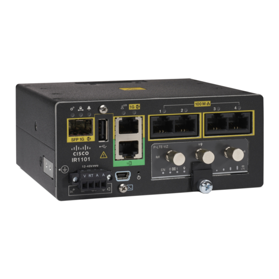
- Page 5 Product Overview Cisco IRM-1100-SPMI Expansion Module The following graphic shows the front panel details of the Cisco IR1101. Figure 4: Cisco IR1101 Front Panel Table 2: SFP GE WAN USB 2.0 RJ45 GE WAN Serial Port FE LAN Ports 1-4...
- Page 6 Product Overview Cisco IRM-1100-SPMI Expansion Module Figure 5: IR-1100-SPMI Expansion Module The following lists the hardware platform features for the Cisco IR-1100-SPMI: • 1 GE SFP • 1 Pluggable slot • 1 Digital I/O connector • 1 mSATA SSD slot...
- Page 7 Product Overview Digital I/O Connector 4 GPIO + 1 Return (Digital I/O) SFP Connector Pluggable Module mSATA SSD Slot Digital I/O LEDs Digital I/O Connector The Digital I/O connector has 4 GPIO connections plus 1 Return connection. The Digital I/O supports Both Dry and Wet contacts up to 60Volts.
- Page 8 Product Overview Digital I/O Connector Name Direction Description DIO4 Digital IO 4 Return Return Digital IO Common Return Digital Input and Output Specifications are described in the following tables. Digital Input Specification is considered “dry contact”, and Digital Output Specification is considered “wet contact”.
- Page 9 • All Cellular interfaces are supported through a Pluggable Module • Micro-Sim, 3FF size. Cisco recommends Industrial Temp micro SIMs that are rated from -40C to +105C. The following two figures show an example of a Pluggable Module. In this case, the LTE Pluggable Module.
- Page 10 Product Overview LTE Category 18 Pluggable Module Figure 8: LTE Pluggable Module (front) LTE-Main SMA GPS SMA Micro USB Debug Port LTE-Div SMA Figure 9: LTE Pluggable Module (with antennas) LTE Category 18 Pluggable Module This module has a new smaller form factor SMA Diversity Antenna for usability and Micro-USB port access. Product Overview...
- Page 11 Product Overview LTE Category 18 Pluggable Module Note The P-LTEAP18-G pluggable module must be installed in the IR1101 Base. It cannot be used in the IRM-1100 Expansion Module. Figure 10: LTE Pluggable - P-LTEAP18-GL Item Description Main 0 Antenna Diversity 1 Antenna...
-
Page 12: Front Panel Icons And Leds
Product Overview mSATA Module mSATA Module Mini-SATA, or mSATA, is a low-profile interface connector that enables more effective Serial ATA (SATA) integration in small form-factor drives roughly the size of a business card, such as solid state disks (SSDs). The mSATA Pluggable Module plugs into the IR-1100-SPMI Expansion Module. The following figure shows the mSATA Pluggable Module. - Page 13 Product Overview Front Panel Icons and LEDs Icon Description/Activity Icon Description/Activity Red, Green, and Blue User Configurable Off — No VPN tunnel Steady Green — At least one VPN tunnel is up Gigabit Ethernet Combo Port RJ45 Fast Ethernet Ports -Link Status 0:1 Off —...
-
Page 14: Supported Cisco Antennas And Antenna Accessories
Expansion Module (Bottom or Right side) Memory The Cisco IR1101 uses flash memory and main memory. The flash memory contains the Cisco OS software image and the boot flash contains the ROMMON boot code. The memory includes: • 4 GB DRAM (soldered down) •... - Page 15 Product Overview Modem Support Table 9: Modem Technology Supported SKU ID Modem Used Description Technology Supported P-LTE-VZ WP7601-G U.S. (Verizon) Single LTE CAT4: B4, B13 Micro SIM P-LTE-US WP7603-G North America (AT&T) LTE CAT4:B2,B4,B5,B12 Dual Micro SIM 3G UMTS DC-HSPA+, HSPA+, HSPA, WCDMA: B2,B4, B5 P-LTE-JN WP7605-G...
- Page 16 25), 1700-MHz and 2100-MHz (band 4 AWS), 2100-MHz (band 1), 2300-MHz (band 30), or 2600-MHz (band 7) networks. The multimode Cisco LTE Advanced 3.0 NIMs are backward compatible with Universal Mobile Telecommunications Service (UMTS) and Dual-Carrier High-Speed Packet Access Plus...
-
Page 17: Power Supply
Supported Power Supply The Cisco IR1101 comes with an external DC power connector. The 4-pin power entry connector (receptacle) is mounted to the unit. The 4-pin power entry mating connector (plug) is attached to the receptacle. It is removed during installation and used to connect to the DC power source, then reattached to provide power to the unit. -
Page 18: Rj45 Ports
ALM IN Alarm Input RJ45 Ports The IR1101 supports one ISOLATED RS232 port which conforms to EIA-561 standard. The RJ45 pinouts are shown in the following graphic. Figure 13: S0 Characteristics The RS232 port is a DTE and its pin out is shown in the following table. -
Page 19: Ethernet And Optical Sfp Modules
You can use any combination of the supported SFP modules listed in the table that follows. Note The IR1101 is designed to operate in the Industrial temperature range (-40C to +85C internal component temperature range) and therefore cannot support commercial rated SFPs. -
Page 20: Dsl Sfp Module
+85C GLC-FE-100FX-RGD 2 km GLC-FE-100LX-RGD 10 km For the most up-to-date list of supported SFP models for Cisco Industrial Ethernet switches, see http://www.cisco.com/en/US/docs/interfaces_modules/transceiver_modules/compatibility/matrix/OL_6981.html#wp138176 DSL SFP Module This section provides an example of installing and removing the DSL SFP module. Attention Prior to installing the DSL SFP Module, please note the following statements: 1. - Page 21 The DSL SFP will only function on IOS-XE release 17.4.1 and above. Due to a change in the IR1101 Faceplate, older routers are not able to use the DSL SFP. There is no viewable version on the IR1101 Faceplate, but you can determine if your router is new enough to use the DSL SFP...
- Page 22 Product Overview DSL SFP Overview Figure 14: Front View Figure 15: Top View The DSL SFP has 2 LEDs built in. The LED positions and definitions are shown in the following: Product Overview...
- Page 23 Product Overview DSL SFP Overview Figure 16: LED 1 Indicator LED State Description LED 1 (Orange) CPE side (expected to be ON when used on an IR router) LED 1 (Orange) Central office side (not supported) Figure 17: LED 2 Indicator LED State Description...
- Page 24 Product Overview Installing the DSL SFP Module Installing the DSL SFP Module Perform the following to install the module: Step 1 Close the SFP-Pull before inserting the SFP module. Step 2 Line up the SFP module and slide it into the cage. Figure 18: Align SFP Module LED 1 will turn orange as an indicator of RT.
- Page 25 Product Overview Removing the DSL SFP Module Removing the DSL SFP Module Perform the following to remove the module: Step 1 Remove the xDSL connection cable from the ports. Step 2 Open the SFP-Pull with your finger and press it to the end. Figure 20: SFP-Pull Step 3 Grasp the SFP module between your thumb and index finger, and carefully remove it from the cage.
- Page 26 Product Overview Removing the DSL SFP Module Product Overview...