Cisco IR1101 Manual
Hide thumbs
Also See for IR1101:
- Hardware installation manual (86 pages) ,
- User manual (26 pages) ,
- Getting started (20 pages)
Advertisement
Quick Links
Product Overview
This chapter provides an overview of the features available for the Cisco IR1101 Industrial Integrated Services
Router and its Expansion Module. It contains the following sections:
•
Product Overview
This chapter provides an overview of the features available for the Cisco IR1101 Industrial Integrated Services
Router and its Expansion Module. It contains the following sections:
Note
Prior to installing this device read the
General Description
The Cisco IR1101 Industrial Integrated Services Router is a next generation modular industrial router which
has a base module with additional Pluggable Modules that can be added. The Pluggable Module provides the
flexibility of adding different interfaces to the IR1101 platform, for example, a cellular module.
The IR1101 ISR also has an Expansion Module that adds key capabilities such as dual LTE Pluggables,
mSATA SSD FRU, SFP, and Digital GPIO connections.
Product Overview, on page 1
Regulatory Compliance and Safety Information
.
Product Overview
1
Advertisement

Related Manuals for Cisco IR1101


Summary of Contents for Cisco IR1101
- Page 1 Pluggable Modules that can be added. The Pluggable Module provides the flexibility of adding different interfaces to the IR1101 platform, for example, a cellular module. The IR1101 ISR also has an Expansion Module that adds key capabilities such as dual LTE Pluggables, mSATA SSD FRU, SFP, and Digital GPIO connections.
-
Page 2: Sku Information
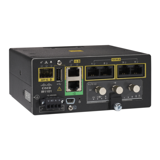
Product Overview SKU Information Figure 1: The IR1101 Industrial Integrated Services Router SKU Information Table 1 lists the different SKUs available for the Cisco IR 1101. Table 1: Supported SKUs for Cisco IR1101 SKU ID Description IR1101-K9 IR1101 Base Unit... -
Page 3: Cisco Ir1101 Series Platform Features
Cisco IR1101 Series Platform Features This section describes the different components of the router. Cisco IR1101 Base Router The following lists the hardware platform features for the Cisco IR1101. • External Power Entry • Nominal: 12 to 48VDC • Absolute min/max: 9.6 to 60VDC •... - Page 4 Cisco IR1101 Base Router Figure 2: Cisco IR1101 Industrial Integrated Services Router Figure 3 Figure 4 shows the IR1101 Base Module Front. Figure 3: Cisco IR1101 Integrated Services Router with USB covers in place Item Details USB 2.0 Port Cover Mini-USB Console Cover...
- Page 5 Product Overview Cisco IRM-1100-SPMI Expansion Module Figure 4 shows the front panel details of the Cisco IR1101. Figure 4: Cisco IR1101 Front Panel SFP GE WAN Grounding Point (on side of device) USB 2.0 DC Power and Alarm Input RJ45 GE WAN...
- Page 6 Product Overview Cisco IRM-1100-SPMI Expansion Module Figure 5: IR-1100-SPMI Expansion Module The following lists the hardware platform features for the Cisco IR-1100-SPMI: • 1 GE SFP (see the supported list of SFP’s here: SFP Module, page 26 • 1 Pluggable slot •...
- Page 7 Product Overview Digital I/O Connector 4 GPIO + 1 Return (Digital I/O) SFP Connector Pluggable Module mSATA SSD Slot Digital I/O LEDs Digital I/O Connector The Digital I/O connector has 4 GPIO connections plus 1 Return connection. The Digital I/O supports Both Dry and Wet contacts up to 60Volts.
- Page 8 Product Overview Digital I/O Connector Pin # Name Direction Description Return Return Digital IO Common Return Digital Input and Output Specifications are described in Table 3 Table 4 Table 3 is considered “dry contact”, and Table 4 is considered “wet contact”. Table 3: Digital Input Specification Specification Minimum...
- Page 9 Pluggable LTE Module Highlights of the LTE Pluggable Module are: • All Cellular interfaces are supported through a Pluggable Module • Micro-Sim, 3FF size. Cisco recommends Industrial Temp micro SIMs that are rated from -40C to +105C. Figures Figure 8 Figure 9 show an example of a Pluggable Module.
- Page 10 This module has a new smaller form factor SMA Diversity Antenna for usability and Micro-USB port access. Note The P-LTEAP18-G pluggable module must be installed in the IR1101 Base. It cannot be used in the IRM-1100 Expansion Module. Product Overview...
- Page 11 Product Overview mSATA Module Figure 10: LTE Pluggable - P-LTEAP18-GL Item Description Main 0 Antenna Diversity 1 Antenna Diversity 0 Antenna Main 1 Antenna Micro USB Debug Port Installing or replacing the SIM modules is covered in Pluggable Module P-LTEAP18-GL Frequency Bands The following table provides the global frequency bands available.
-
Page 12: Front Panel Icons And Leds
Product Overview Front Panel Icons and LEDs Figure 11: mSATA Pluggable Module Highlights of the mSATA Pluggable Module are: • Provides an additional 100GB of additional flash memory storage • Main purpose is to provide space to store application data for IOx •... - Page 13 Product Overview Front Panel Icons and LEDs Icon Description/Activity Icon Description/Activity Gigabit Ethernet Combo Port RJ45 Fast Ethernet Ports -Link Status 0:1 Off — No Link Off — No link Solid Green — Copper Link up, no activity Steady Green — Link is up Flashing Green —...
-
Page 14: Supported Cisco Antennas And Antenna Accessories
Product Overview Memory Memory The Cisco IR1101 uses flash memory and main memory. The flash memory contains the Cisco OS software image and the boot flash contains the ROMMON boot code. The memory includes: • 4 GB DRAM (soldered down) •... - Page 15 Low), 900-MHz (band 8), 1500-MHz (band 21), 1800-MHz (band 3), 2100-MHz (band 1), or 2600-MHz (band 7) networks; the multimode Cisco LTE Advanced 3.0 NIMs are backward-compatible with UMTS and DC-HSPA+: 800 MHz (band 19 Japan), 850 MHz (band 5), 850 MHz (band 6 Japan), 900 MHz (band 8), 1800 MHz (band 9), 2100 MHz (band 1), and TD-SCDMA 39.
- Page 16 25), 1700-MHz and 2100-MHz (band 4 AWS), 2100-MHz (band 1), 2300-MHz (band 30), or 2600-MHz (band 7) networks. The multimode Cisco LTE Advanced 3.0 NIMs are backward compatible with Universal Mobile Telecommunications Service (UMTS) and Dual-Carrier High-Speed Packet Access Plus...
-
Page 17: Power Supply
Supported Power Supply The Cisco IR1101 comes with an external DC power connector. The 4-pin power entry connector (receptacle) is mounted to the unit. The 4-pin power entry mating connector (plug) is attached to the receptacle. It is removed during installation and used to connect to the DC power source, then reattached to provide power to the unit. - Page 18 You can use any combination of the supported SFP modules listed in the table that follows. Note: The IR1101 is designed to operate in the Industrial temperature range (-40C to +85C internal component temperature range) and therefore cannot support commercial rated SFPs.
- Page 19 +85C GLC-FE-100FX-RGD 2 km GLC-FE-100LX-RGD 10 km For the most up-to-date list of supported SFP models for Cisco Industrial Ethernet switches, see http://www.cisco.com/en/US/docs/interfaces_modules/transceiver_modules/compatibility/matrix/OL_6981.html#wp138176 DSL SFP Module This section provides an example of installing and removing the DSL SFP module. Attention Prior to installing the DSL SFP Module, please note the following statements: 1.
- Page 20 Product Overview DSL SFP Overview Note SFP-VADSL2+-I was evaluated to country specific regulatory requirements only. The product was not evaluated to IEC 61850-3 and IEEE1613 substation / utility standards. DSL SFP Overview The DSL SFP interface is an 8 pin modular jack. The following table shows the pin-out assignments: Pin Number Pin Assignment Not Used...
- Page 21 Product Overview DSL SFP Overview Figure 14: Front View Product Overview...
- Page 22 Product Overview DSL SFP Overview Figure 15: Top View The DSL SFP has 2 LEDs built in. The LED positions and definitions are shown in the following: Product Overview...
- Page 23 Product Overview DSL SFP Overview Figure 16: LED 1 Indicator LED State Description LED 1 (Orange) CPE Mode/RT Mode/Primary Mode Customer Premises Equipment (CPE) or Central Office (CO) LED LED 1 (Orange) CPE Mode/RT Mode/Subordinate Mode CO/CPE LED Figure 17: LED 2 Indicator LED State Description...
- Page 24 Product Overview Installing the DSL SFP Module Indicator LED State Description LED 2 (Green) Extremely Rapid Flash Packet Transmit xDSL Status LED Installing the DSL SFP Module Perform the following to install the module: Step 1 Close the SFP-Pull before inserting the SFP module. Step 2 Line up the SFP module and slide it into the cage.
- Page 25 Product Overview Removing the DSL SFP Module Link time takes about 60 seconds. Fast flashing green LED 2 indicates DSL training. LED 2 on both VDSL2 SFP Modules (CO & RT) turns solid green when the devices link up. Removing the DSL SFP Module Perform the following to remove the module: Step 1 Remove the xDSL connection cable from the ports.
- Page 26 Product Overview Removing the DSL SFP Module Product Overview...