
Related Manuals for Sentry SBC


Summary of Contents for Sentry SBC
- Page 1 Original Instructions Installation, Operation & Maintenance Manual Sentry SBC Controller Sampler Controllers S-AS-IOM-00409-3 11-20 Keep for future reference.
- Page 2 Copyright © 2020 by Sentry Equipment Corp . All rights reserved . All product and company names are property of their respective owners . This document contains proprietary information . No part of this document may be photocopied or reproduced without the prior written consent of Sentry Equipment Corp .
-
Page 3: Table Of Contents
Appendix B: Other Samplers . . . . . . . . . . . . . . . . . . . . . . . . . . . . . . . .20 Sentry SBC Controller... -
Page 4: Safety Information
. Â NOTE Information that requires special emphasis . Â TIP Alternate techniques or clarifying information. SHALL: This word is understood to be mandatory . SHOULD: This word is understood to be advisory . Original Instructions Sentry Equipment Corp... -
Page 5: General Safety Precautions
. Moving parts! This equipment may contain moving parts . All drive guards and doors must be secured in place when this machine is being operated . Sentry SBC Controller Original Instructions... -
Page 6: General Description
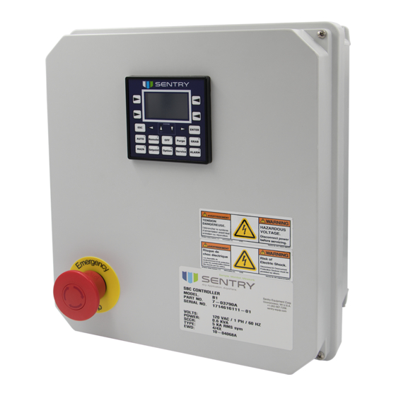
General Description  NOTE Information provided in this manual covers all standard features of the Model SBC . Certain features do not apply to all applications . The software displays the options that apply to your application . The Sentry® SBC controller is a dedicated logic control system capable of controlling many automatic samplers in the Sentry product line including liquid, slurry, and bulk solids samplers . -
Page 7: Installation
 NOTE Inputs I3 through I7 are located on the Index Cabinet . Inputs H1 through H4 and A1 are field-mounted devices . The signals are processed in the Sentry SBC Controller . I1 . REMOTE ENABLE: External contact from customer which, when open, prohibits all operation of the sampler . If not used, leave terminals TB2 1 and 2 wired together . -
Page 8: Outputs
4. ENTER: Accepts new values; selects menu options; enters editing mode . 5. Numbers: In editing mode, all of the function keys can be used to enter numbers, which are shown in gray on the upper right hand corners of the keys Original Instructions Sentry Equipment Corp... - Page 9 3. Option: Menu of the available program options and routing to pertinent screens . 4. Service: Menu of service-related options such as I/O Status, Quick Start, Operation Sequence, Default settings, and Cycle Counter . 5. Alarm: System alarm log . Sentry SBC Controller Original Instructions...
-
Page 10: Starting And Operating The Controller
– If contact is removed in the middle of a sampling cycle, the sampler completes the cycle and then stops . – A momentary closure of the remote contact results in a single sample being taken . Original Instructions Sentry Equipment Corp... -
Page 11: Controller Options
– When all of the jars in the indexing cabinet are full, replace them with empty jars . – Reset the jar counter by pressing the lower soft key to the right of the screen . Sentry SBC Controller Original Instructions... - Page 12 . Air Eject This option is available only on specific samplers . Consult with a Sentry sales representative to see if the air eject option is available for your application . Air eject allows a shot of air to flow through the sampler after the sample has been taken .
-
Page 13: Maintenance Functions
ƒ Use the small arrow keys to navigate to the desired option, and then press the Enter key to select the menu item . ƒ Press the ESC key to return to the Maintenance menu . Sentry SBC Controller Original Instructions... - Page 14 . This counter is limited to 65,536 . The ETERNAL counter cannot be reset and displays the number of samples ever taken by the sampler . This counter is limited to 4,294,967,296 . Original Instructions Sentry Equipment Corp...
-
Page 15: Alarm Function
Contact Us If a problem should arise with the sampler or controller, please contact Sentry at the number listed on the screen as shown below . Configuration This selection is password protected and is for factory use only . Software The Software screen lists the revisions for the loaded software . -
Page 16: Modbus Communications
MODBUS Communications The Sentry SBC Controller is designed to communicate via MODBUS . It is set to operate as a slave-only and the address range is 1-247 . See the chart below for proper addressing . SBC Modbus Mapping Utilize port MJ2 for Modbus communications! -
Page 17: Standard Warranty
RS-485 (Utilizes Data Offset of 1) Standard Warranty Sentry Equipment Corp (“Seller”) warrants products manufactured by it and supplied hereunder (“Products”) to be free from defects in workmanship and, to the extent materials are selected by Seller, to be free from defects in materials, in... -
Page 18: Customer Support
ƒ Field Service & Retrofi ts—When a problem needs immediate attention . ƒ Replacements Parts & Consumables—Order your replacement parts and consumables . ƒ Sentry ProShield Services—Select from four ProShield Guardian service plans providing diff erent levels of support to protect your large system investments with regularly scheduled maintenance . - Page 19 ƒ Press the AUTO key to start sampling . The sampler will immediately extend the plunger into the process stream and start the sampling cycle . If this does not occur, check to see if the REMOTE ENABLE input is present . Without this input, the sampler will not function under any circumstances . Sentry SBC Controller Original Instructions...
-
Page 20: Appendix B: Other Samplers
Model ISOLOK® 1. Energize solenoid, air cylinder extends sampler, start sample timer 2. Sample time expires 3. Solenoid de-energized, air cylinder retracts sampler, start cycle timer 4. Cycle time expires 5. Go to step 1 Original Instructions Sentry Equipment Corp... - Page 21 3. Solenoid de-energized, air cylinder retracts sample tube, start auger delay timer 4. Auger delay time expires 5. Start motor, start auger run timer 6. Auger run timer expires 7. Stop motor, start cycle timer 8. Cycle time expires 9. Go to step 1 Sentry SBC Controller Original Instructions...
- Page 22 Model SA/E & GE 1. Energize motor, motor moves pelican across the sample flow 2. Sensor indicates pelican is under dust seal, de-energize motor, start cycle timer 3. Cycle time expires 4. Go to step 1 Original Instructions Sentry Equipment Corp...
- Page 23 REMOTE ENABLE input is present . Without this input, the sampler will not function under any circumstances . To see if the remote enable is present, please refer to drawing 10-0468A that came with the SBC controller and confirm contact is being made between terminals TB2 3&4 Sentry SBC Controller...
- Page 24 Serving customers in more than 50 countries across six continents worldwide. sentry-equip.com 966 Blue Ribbon Circle North, Oconomowoc, WI 53066 U.S.A. | +1-262-567-7256 | support@sentry-equip.com...