
Related Manuals for Samsung AJTNLDCH Series


Summary of Contents for Samsung AJTNLDCH Series
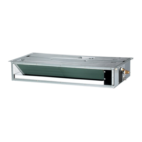
- Page 1 Air conditioner Installation manual AJ***TNLDCH • Thank you for purchasing this Samsung air conditioner. • Before operating this unit, please read this manual carefully and retain it for future reference.
-
Page 2: Table Of Contents
Contents Safety Information Installation Procedure Step 1 Checking and preparing accessories Step 2 Choosing the installation location Step 3 Optional: Insulating the body of the indoor unit Step 4 Installing the indoor unit Step 5 Purging inert gas from the indoor unit Step 6 Cutting and flaring the pipes Step 7 Connecting the assembly pipes to the refrigerant pipes Step 8 Performing the gas leak test... -
Page 3: Safety Information
• This manual explains how to install an indoor unit with may be injured if protective equipment is not properly a split system with two SAMSUNG units. The use of equipped. other types of units with different control systems may damage the units and invalidate the warranty. - Page 4 Safety Information Safety Information • Upon receipt, inspect the product to verify that it has not • Always verify that electric connections (cable been damaged during transport. If the product appears entry, section of leads, protections…) are compliant damaged, DO NOT INSTALL it and immediately report with the electric specifications and with the the damage to the carrier or retailer (if the installer or instructions provided in the wiring scheme.
-
Page 5: Installation Procedure
Installation Procedure Step 1 Checking and preparing Step 2 Choosing the installation accessories location The following accessories are supplied with the indoor unit. The type and quantity may differ, depending on the Installation location requirements specifications. • There must be no obstacles near the air inlet and User’s Installation outlet. - Page 6 Installation Procedure TNLDCH Unit: inch 0.79 30.16 0.51 4.96 1.38 5.75 6.10 5.12 1.38 5.47 1.30 10.83 6.93 10.83 30.53 31.73 37.21 (Suspension position) 7X3.94=27.56 29.32 (Air outlet duct flange) 35.43 Suction side Discharge side Name Description Liquid pipe connection ø1/4"...
-
Page 7: Step 3 Optional: Insulating The Body Of The Indoor Unit
Step 3 Optional: Insulating the body Spacing requirements of the indoor unit Space requirements for installation & service. Construction Standard for Inspection opening Insulation Guide An inspection opening is required for service and unit replace- ment. 1) If the ceiling is a grid type, an inspection opening is not required. -
Page 8: Step 4 Installing The Indoor Unit
Installation Procedure Step 4 Installing the indoor unit • If the length of suspension bolt is more than 4.92 ft, it is required to prevent vibration. • If this is not possible, create an opening on the 1 Place the pattern sheet on the ceiling at the spot false ceiling in order to be able to use it to perform where you want to install the indoor unit. -
Page 9: Step 5 Purging Inert Gas From The Indoor Unit
Step 5 Purging inert gas from the When the drain hose is installed to the right. indoor unit The indoor unit comes with nitrogen gas (inert gas) charged at the factory. Therefore, all inert gas must be purged before connecting the assembly piping. Drain hose port Unscrew the pinch pipe at the end of each refrigerant pipe. -
Page 10: Step 6 Cutting And Flaring The Pipes
Installation Procedure Step 6 Cutting and flaring the pipes 1 Make sure that you have the required tools available: pipe cutter, reamer, flaring tool, and pipe holder. 2 If you wish to shorten the pipes, cut them with a pipe cutter, ensuring that the cut edge remains at a 90°... -
Page 11: Step 7 Connecting The Assembly Pipes To The Refrigerant Pipes
Step 7 Connecting the assembly 3 Cut off any excess foam insulation. pipes to the refrigerant pipes 4 Make sure that the bent sections of pipe are not kinked or cracked. There are two refrigerant pipes of different diameters : •... -
Page 12: Step 9 Insulating The Refrigerant Pipes
Installation Procedure CAUTION • Be sure to wrap insulation tightly without any gaps. 3 Finish wrapping insulating tape around the rest of the Gas side pipes leading to the outdoor unit. 4 The pipes and electrical cables connecting the indoor unit with the outdoor unit must be fixed to the wall with suitable ducts. -
Page 13: Step 10 Installing The Drain Hose And Drain Pipe
Insulation type (heating/cooling) Pipe size Standard (Less than 86°F, 85%) High humidity (Over 86°F, 85%) Pipe Remarks EPDM, NBR inch inch inch Ø1/4~Ø3/8 Liquid pipe Ø1/2~Ø3/4 The internal Ø1/4 temperature is higher Ø3/8 than 248°F. Gas pipe Ø1/2 Ø5/8 • When installing insulation in the conditions below, 5 Push the drain hose up to insulation when connecting use the same insulation that is used for high the drain hose to drain socket. - Page 14 Installation Procedure • If it is necessary to increase the height of the drain pipe, install the drain pipe straight within Be horizontal 11.81 inch from the drain hose port. If it is raised higher than 21.65 inch, there may be water leaks. Indoor unit 0.79 inch or more Drain hose...
-
Page 15: Step 11 Performing The Drainage Test
Step 11 Performing the drainage test 4 Reassemble the electrical component box cover, carefully tightening the screw. 1 Pour water into the drain pan inside the the indoor unit as shown in the figure below (approximately 0.5 gallons) 2 Confirm that the water flows out through the drain hose. -
Page 16: Step 13 Optional: Extending The Power Cable
Installation Procedure • Power supply cords of parts of appliances for outdoor Step 13 Optional: Extending the power use shall not be lighter than polychloroprene sheathed cable flexible cord. (Code designation IEC:60245 IEC 57 / CENELEC: H05RN-F or IEC:60245 IEC 66 / CENELEC: 1 Prepare the following tools. - Page 17 6 Apply heat to the contraction tube to contract it. Method 1 Method 2 Connection sleeve Connection sleeve CAUTION 7 After tube contraction work is completed, wrap it with • If cable wires are connected without using connecting the insulation tape to finish. sleeves, their contact area becomes reduced, or corrosion develops on the outer surfaces of the wires Three or more layers of insulation are required.
- Page 18 Installation Procedure Step 14 Setting the indoor unit CAUTION addresses and the installation options • The total number of available options are 24: SEG1 to SEG24. You cannot set both the indoor unit addresses and the installation options at the same time. •...
- Page 19 Take the steps presented in the following table: Steps Remote control display 1 Set the SEG2 and SEG3 values: a Set the SEG2 value by pressing the (Low Fan) button repeatedly until the value you want to set appears on the remote control display. SEG2 b Set the SEG3 value by pressing the (High Fan) button repeatedly until the...
- Page 20 Installation Procedure Steps Remote control display 6 Press the (Mode) button. Fan and On appear on the remote control display. 7 Set the SEG9 and SEG10 values: a Set the SEG9 value by pressing the (Low Fan) button repeatedly until the value you want to set appears on the remote control display.
- Page 21 Steps Remote control display 11 Set the SEG14 and SEG15 values: a Set the SEG14 value by pressing the (Low Fan) button repeatedly until the value you want to set appears on the remote control display. SEG14 b Set the SEG15 value by pressing the (High Fan) button repeatedly until the value you want to set appears on the remote control display.
- Page 22 Installation Procedure Steps Remote control display 16 Press the (Mode) button. Fan and Off appear on the remote control display. 17 Set the SEG21 and SEG22 values: a Set the SEG21 value by pressing the (Low Fan) button repeatedly until the value you want to set appears on the remote control display.
- Page 23 3 Check whether the option values that you have set are Setting the indoor unit address and installation option correct by pressing the (Mode) button repeatedly [SEG2, SEG3] [SEG4, SEG5] [SEG6, SEG8] [SEG9, SEG10] 1 Make sure that the power is supplied to the indoor unit.
- Page 24 Installation Procedure Setting an indoor unit address (MAIN/RMC) • The indoor unit address are set to 0A0000-100000-200000-300000 by default. Option No. : 0AXXXX-1XXXXX-2XXXXX-3XXXXX Option SEG1 SEG2 SEG3 SEG4 SEG5 SEG6 Setting main 100-digit of indoor 10-digit of indoor A single digit of Explanation Page Mode...
- Page 25 Setting an indoor unit installation option (suitable for the condition of each installation location) • The indoor unit installation option are set to 020010-120000-200000-300100 by default. • Set the indoor unit option by wireless remote controller. When entering Address option, connect remote controller receiver.
- Page 26 Installation Procedure Installation option (Detailed) Option No. : 02XXXX-1XXXXX-2XXXXX-3XXXXX Option SEG1 SEG2 SEG3 SEG4 SEG5 SEG6 Use of external room temperature sensor / Use of central Function Page Mode Minimizing fan operation when thermostat is off control Indication Details Indication Details Details Indication...
- Page 27 Option SEG13 SEG14 SEG15 SEG16 SEG17 SEG18 Setting the output of Maximum filter Function Page Use of external control Ionizer Buzzer control external control usage time Indication Details Indication Details Indication Details Indication Details Indication Details Indication Details Disuse On/Off Sub, Existing Control Window Use of...
- Page 28 Installation Procedure Changing the addresses and options individually When you want to change the value of a specific option, refer to the following table and follow the steps in Common steps for setting the addresses and options on page 18 Option SEG1 SEG2...
-
Page 29: Troubleshooting
Troubleshooting LED lamp display Operation Defrost Timer Filter Abnormal conditions Power reset Error of tempreature sensor in the indoor unit (Open/ Short) Error of heat exchanger sensor in the indoor unit (Open/ Short) Error of fan motor in the indoor unit Error of the outdoor temperature sensor Error of the condensor temperature sensor Error of the discharge temperature sensor...