Table of Contents
Advertisement
Advertisement
Table of Contents

Related Manuals for Asus Terminator P4 533A


Summary of Contents for Asus Terminator P4 533A
- Page 1 ® Terminator P4 533A Barebone System User’s Guide...
-
Page 2: Disclaimer/Copyrights
Product warranty or service will not be extended if: (1) the product is repaired, modified or altered, unless such repair, modification of alteration is authorized in writing by ASUS; or (2) the serial number of the product is defaced or missing. -
Page 3: Table Of Contents
Disclaimer/Copyrights ... 2 Notices ... 5 Safety information ... 6 About this guide ... 7 ASUS contact information ... 9 System package contents ... 10 Chapter 1: System Introduction ... 11 1.1 Front Panel Features ... 12 1.2 Rear Panel Features ... 13 1.3 Internal Features ... - Page 4 5.2 Support CD information ... 88 5.2.1 Running the support CD ... 88 5.2.2 Installation menus ... 89 5.2.3 Software and drivers description ... 90 5.3 Software information ... 92 5.3.1 ASUS Update ... 92 5.3.2 ASUS PC Probe ... 94...
-
Page 5: Notices
Notices Federal Communications Commission Statement This device complies with FCC Rules Part 15. Operation is subject to the following two conditions: • This device may not cause harmful interference, and • This device must accept any interference received including interference that may cause undesired operation. This equipment has been tested and found to comply with the limits for a Class B digital device, pursuant to Part 15 of the FCC Rules. -
Page 6: Safety Information
Safety information Electrical safety • To prevent electrical shock hazard, disconnect the power cable from the electrical outlet before relocating the system. • When adding or removing devices to or from the system, ensure that the power cables for the devices are unplugged before the signal cables are connected. -
Page 7: About This Guide
About this guide Audience This guide provides general information and installation instructions about the ASUS Terminator P4 533A Barebone System. This guide is intended for experienced users and integrators with hardware knowledge of personal computers. How this guide is organized... -
Page 8: Conventions Used In This Guide
Refer to the following sources for additional information and for product and software updates. ASUS Websites The ASUS websites worldwide provide updated information on ASUS hardware and software products. The ASUS websites are listed on page 9. Optional Documentation Your product package may include optional documentation, such as warranty flyers, that may have been added by your dealer. -
Page 9: Asus Contact Information
Technical Support Support Fax: +1-510-608-4555 General Support: +1-502-933-8713 Web Site: www.asus.com Support Email: tsd@asus.com ASUS COMPUTER GmbH (Germany and Austria) Address: Harkortstr. 25, 40880 Ratingen, BRD, Germany General Fax: +49-2102-442066 General Email: sales@asuscom.de (for marketing requests only) Technical Support Support Hotline:... -
Page 10: System Package Contents
System package contents Check your ASUS Terminator P4 533A pacakge for the following items: Barebone system ASUS P4SC-EA motherboard Switching power supply (PFC or non-PFC) 1.44MB floppy disk drive CD-ROM Drive (optional) 56K PCI modem card (optional) Support CD User’s guide NOTE Optional items may not be present in your package. -
Page 11: Chapter 1: System Introduction
Chapter 1 This chapter gives a general description of the ASUS Terminator P4 533A barebone system. It includes introduction on the front and rear panel features, and the internal features. ASUS Terminator P4 533A Barebone System... -
Page 12: Front Panel Features
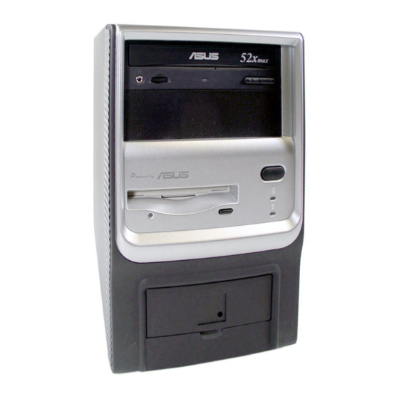
Front Panel Features The ASUS Terminator P4 533A barebone system is composed of the ASUS P4SC-EA motherboard, a power supply, and a floppy disk drive in the ASUS TriOptix form factor chassis. The chassis front bezel may vary as shown. -
Page 13: Rear Panel Features
Rear Panel Features The rear panel of the ASUS Terminator P4 533A barebone system includes the standard PC99 I/O connectors for external devices, power supply socket, and optional modem connectors. The following figure shows the rear panel features. Game/MIDI Connector... -
Page 14: Internal Features
Internal Features The figure below shows the internal view of the system when you remove the cover and flip out the drive frame. The standard components already installed in the system and the locations of the available drive bays are pointed out. - Page 15 Chapter 2 This chapter tells how to install components into the barebone system through illustrated step-by-step instructions. ASUS Terminator P4 533A Barebone System...
-
Page 16: Chapter 2: Basic Installation
Remove the cover The chassis cover is secured by a thumbscrew located on the rear panel. Follow these steps to remove the chassis cover. Turn the captive thumbscrew counter-clockwise to release the cover. You don’t have to remove the thumbscrew from the chassis. -
Page 17: Detach The Drive Frame
Power socket module IMPORTANT You must release the power socket module from the rear panel before detaching the drive frame to avoid breaking the power cable. ASUS Terminator P4 533A Barebone System Power socket module screw... - Page 18 Place your thumb on the right edge of the power socket module, then slide the module to the right until it is completely detached from the rear panel. Unlatch the drive frame by pulling it outward. NOTE The drive frame has a swivel (hinge-like) edge that is attached to the main chassis.
-
Page 19: Install A Cpu
90°-100° angle. IMPORTANT Make sure that the socket lever is lifted up to 90°-100° angle, otherwise the CPU does not fit in completely. ASUS Terminator P4 533A Barebone System Socket lever 90 - 100... - Page 20 Position the CPU above the socket such that its marked corner (gold mark) matches the base of the socket lever. Carefully insert the CPU into the socket until it fits in place. CAUTION The CPU fits only in one correct orientation. DO NOT force the CPU into the socket to prevent bending the pins and damaging the CPU! When the CPU is in place, press it firmly on the socket...
-
Page 21: Install The Cpu Heatsink And Fan
Orient the bracket with the locking lever beside the DIMM sockets. Snap the hook of the retention bracket into the hole of the retention module. ASUS Terminator P4 533A Barebone System Retention bracket Locking lever hooked to the hole of the retention module... - Page 22 Carefully press down the locking lever on the other side of the bracket and hook its end into the hole of the retention module to secure the fan heatsink assembly in place. Follow step 2 to 4 to install the second bracket.
-
Page 23: Install System Memory
A DDR DIMM is keyed with a notch so that it fits in only one direction. DO NOT force a DIMM into a socket to avoid damaging the DIMM. ASUS Terminator P4 533A Barebone System DDR DIMM sockets DIMM notch... -
Page 24: Install A Hard Disk Drive
2.6 Install a hard disk drive The chassis has one 3.5-inch hard disk drive (HDD) bay right under the 5.25-inch bay. The following figures show the internal and external views of the HDD bay location. Internal View Follow these steps to install an IDE HDD. - Page 25 Connect the other end of the IDE ribbon cable to the primary IDE connector (blue connector labeled PRI_IDE1) on the motherboard. ASUS Terminator P4 533A Barebone System Red Stripe to Pin 1 IDE Ribbon Cable Power Cable (P3) Primary IDE connector...
-
Page 26: Install A Cd-Rom Drive
Install a CD-ROM drive A CD-ROM drive is an optional item in this barebone system. Refer to the instructions in this section if you acquired a model without a CD-ROM. Follow these steps to install a CD-ROM drive. Place the chassis upright. Insert the CD-ROM drive into the upper 5.25-inch drive bay. - Page 27 Connect the other end of the audio cable to the black 4-pin connector labeled CD on the motherboard. CD-ROM Connector (CD1) ASUS Terminator P4 533A Barebone System CD-ROM Audio Cable IDE Ribbon Cable Red Stripe to Pin 1 Power Cable (P1) Secondary IDE connector...
-
Page 28: Install An Expansion Card
2.8 Install an expansion card The motherboard has one 32-bit PCI slot and one Accelerated Graphic Port (AGP) slot. Follow these steps to install a PCI or AGP card. Place the chassis on its side. Remove the metal bracket opposite the slot that you wish to use. -
Page 29: Re-Connect Cables
Connect the power switch and power LED cables to their respective leads in the PANEL1 connector on the motherboard. • Connect the HDD LED cable to the 2-pin lead marked IDE_LED1. ASUS Terminator P4 533A Barebone System PANEL1 Connector Power LED Message LED SMI Lead Requires an ATX power supply. -
Page 30: Uaex And Card Reader Modules
2.9.2 UAEX and card reader modules The system front I/O panel has two modules, the UAEX and a card reader, that contain the front panel I/O ports and the connectors to the motherboard. UAEX module Connect to MIC_LOUT1 connector on the motherboard CF Card Reader module Connector locations on the motherboard USB_34 USB_56... -
Page 31: Replace The Cover
Turn the chassis upright. Place the cover over the chassis leaving about two inches from the rear panel. ASUS Terminator P4 533A Barebone System Protruding Tab... - Page 32 Fit the rail tabs on the sides and bottom of the cover to the edges of the chassis. Push the cover towards the rear until it fits. The locking tab snaps into the hole on the chassis indicating that the cover is in place.
-
Page 33: Connect External Devices
2.11 Connect External Devices The figure below shows the specific connectors and devices that you can connect to the rear panel ports. Serial Game/MIDI PS/2 KB PS/2 Mouse Parallel Line Out Line In RJ-45 ASUS Terminator P4 533A Barebone System... -
Page 34: Power Supply Specifications
2.12 Power Supply Specifications 2.12.1 Input Characteristics Input Voltage Range Range 1 Range 2 Input Frequency Range Maximum Input ac Current Inrush Current Efficiency 2.12.2 Output Characteristics Output Load Range Voltage 0.5A +12V 0.45A -12V +5VSB 0.05A +3V3 2.12.3 Over-Voltage Protection (OVP) Output Voltage +12V +3.3V... -
Page 35: Chapter 3: Motherboard Info
USB/audio board located on the front panel. IMPORTANT The ASUS Terminator P4 533A barebone system is designed to support a motherboard that measures 23 cm (9.06 in) x 22.4 cm (8.82 in). It is not recommended to install any motherboard of other sizes. -
Page 36: Introduction
Introduction The ASUS P4SC-EA motherboard comes already installed in the ASUS Terminator P4 533A barebone system. For future upgrades or system reconfiguration, this chapter provides technical information about the motherboard. 3.2 Motherboard components Chapter 3: Motherboard information... - Page 37 Media I/O, this controller integrates the audio controller with AC’97 Interface, Ethernet MAC, Dual Universal Serial Bus Host controllers, IDE Master/Slave controllers, and the MuTIOL Connect to PCI Bridge. ASUS Terminator P4 533A Barebone System Pentium 4 478/Northwood Processor with ®...
- Page 38 AGP slot. This Accelerated Graphic Port (AGP) slot supports AGP 4X mode cards for 3D graphical applications. ASUS ASIC. This chip performs multiple system functions that include hardware and system monitoring, IRQ routing, etc. PCI slot. This 32-bit PCI 2.2 expansion slot supports bus master PCI cards like SCSI or LAN cards with 133MB/s maximum throughput.
-
Page 39: Motherboard Layout
RJ-45 LANLED USBPWR_12 T:Port2 B:Port1 CHIP AUX1 Audio Codec MODEM1 MDC1 MIC_LOUT1 ASUS Terminator P4 533A Barebone System 23cm (9.06in) Flash FLOPPY1 BIOS DDR DIMM2 (64/72-bit, 184-pin module) DDR DIMM1 (64/72-bit, 184-pin module) P4SC-EA Socket 478 HOST/ Memory Controller ®... -
Page 40: Central Processing Unit (Cpu)
3.4 Central Processing Unit (CPU) The motherboard comes with a surface mount 478-pin Zero Insertion Force (ZIF) socket. This socket is specifically designed for the Intel Pentium 4 478/Northwood Processor. ® The Intel Pentium 4 Processor in the 478-pin package uses the Flip-Chip Pin Grid Array 2 (FC-PGA2) package technology, and includes the Intel NetBurst™... -
Page 41: System Memory
64MB, 128MB, 256MB, 512MB, 1GB Total system memory (Max. 2GB) NOTE Refer to section “2.5 Install system memory” for instructions on installing DDR DIMMs. ASUS Terminator P4 533A Barebone System 104 Pins 80 Pins Total Memory x1 = x1 =... -
Page 42: Expansion Slots
3.6 Expansion slots In the future, you may need to install expansion cards. The motherboard has two PCI slots. 3.6.1 Configuring an expansion card After physically installing the expansion card, configure the card by adjusting the software settings. Turn on the system and change the necessary BIOS settings, if any. See Chapter 4 for information on BIOS setup. -
Page 43: Jumpers
3. Make sure to set the jumpers to +5VSB if you wish to wake up the system from S3 sleep mode. P4SC-EA ® P4SC-EA USB Device Wake Up ASUS Terminator P4 533A Barebone System USBPWR_12 +5VSB (Default) USBPWR_34 +5VSB... - Page 44 Clear RTC RAM (CLRTC1) This jumper allows you to clear the Real Time Clock (RTC) RAM in CMOS. You can clear the CMOS memory of date, time, and system setup parameters by erasing the CMOS RTC RAM data. The RAM data in CMOS, that include system setup information such as system passwords, is powered by the onboard button cell battery.
-
Page 45: Connectors
For UltraDMA/133/100/66 IDE devices, use an 80-conductor IDE cable. P4SC-EA ® P4SC-EA IDE Connectors ASUS Terminator P4 533A Barebone System NOTE: Orient the red markings (usually zigzag) on the IDE ribbon cable to PIN 1. PIN 1... - Page 46 Floppy disk drive connector (34-1 pin FLOPPY1) This connector supports the provided floppy drive ribbon cable. After connecting one end to the motherboard, connect the other end to the floppy drive. (Pin 5 is removed to prevent incorrect insertion when using ribbon cables with pin 5 plug).
- Page 47 1A on the +5-volt standby lead (+5VSB). The minimum recommended wattage is 230W, or 300W for a fully configured system. The system may become unstable and may experience difficulty powering up if the power supply is inadequate. ASUS Terminator P4 533A Barebone System ATXPWR1 +12.0Volts +5V Standby...
- Page 48 CPU, Chassis, and Power Fan Connectors (3-pin CPU_FAN1, CHA_FAN1) The three fan connectors support cooling fans of 350mA (4.2 Watts) or a total of 1A (12W) at +12V. Orient the fans so that the heat sink fins allow air flow to go across the onboard heat sinks instead of the expansion slots.
- Page 49 It also allows the sharing of mono_in (such as a phone) and a mono_out (such as a speaker) between the audio and a voice modem card. P4SC-EA ® P4SC-EA Internal Audio Connectors ASUS Terminator P4 533A Barebone System USB_34 USB_56 AUX1 (White) Left Audio Channel Ground...
- Page 50 Front panel audio connectors (5-1 pin MIC_LOUT1) This connector connects to a front panel audio module using an audio cable. If your chassis has this audio module, you may conveniently connect a microphone and a speaker/headphone on the front panel. ®...
- Page 51 “green” mode, where system activity is instantly decreased to save power and to expand the life of certain system components. Attach the case-mounted suspend switch to this 2-pin connector. ASUS Terminator P4 533A Barebone System Speaker Connector Power LED...
- Page 52 • ATX Power Switch / Soft-Off Switch Lead (2-pin PWR) This connector connects a switch that controls the system power. Pressing the power switch turns the system between ON and SLEEP, or ON and SOFT OFF, depending on the BIOS or OS settings. Pressing the power switch while in the ON mode for more than 4 seconds turns the system OFF.
-
Page 53: Chapter 4: Bios Information
Chapter 4 This chapter tells how to change system settings through the BIOS Setup menus. It includes detailed descriptions of the BIOS parameters. ASUS Terminator P4 533A Barebone System... -
Page 54: Managing And Updating The Bios
Managing and updating the BIOS 4.1.1 Using the computer system for the first time It is recommended that you save a copy of the original motherboard BIOS along with a Flash Memory Writer utility (AFLASH.EXE) to a bootable floppy disk in case you need to reinstall the BIOS later. AFLASH.EXE is a Flash Memory Writer utility that updates the BIOS by uploading a new BIOS file to the programmable flash ROM on the motherboard. - Page 55 Select 1. Save Current BIOS to File from the Main menu and press <Enter>. The Save Current BIOS To File screen appears. Type a filename and the path, for example, A:\XXX-XX.XXX, then press <Enter>. ASUS Terminator P4 533A Barebone System...
-
Page 56: Updating Bios Procedures
BIOS revision will solve your problems. Careless updating may result to more problems with the motherboard! Download an updated ASUS BIOS file from the Internet (WWW or FTP) (see ASUS CONTACT INFORMATION on page x for details) and save to the boot floppy disk you created earlier. - Page 57 If the Flash Memory Writer utility is not able to successfully update a complete BIOS file, the system may not boot. If this happens, call the ASUS service center for support. ASUS Terminator P4 533A Barebone System...
-
Page 58: Bios Setup Program
4.2 BIOS Setup program This motherboard supports a programmable EEPROM that you can update using the provided utility described in section “4.1 Managing and updating your BIOS.” Use the BIOS Setup program when you are installing a motherboard, reconfiguring your system, or prompted to “Run Setup”. This section explains how to configure your system using this utility. -
Page 59: Bios Menu Bar
<Enter> <Home> or <PgUp> <End> or <PgDn> <F5> <F10> ASUS Terminator P4 533A Barebone System Function Description Displays the General Help screen from anywhere in the BIOS Setup Jumps to the Exit menu or returns to the main menu from... -
Page 60: General Help
General help In addition to the Item Specific Help window, the BIOS setup program also provides a General Help screen. You may launch this screen from any menu by simply pressing <F1> or the <Alt> + <H> combination. The General Help screen lists the legend keys and their corresponding functions. -
Page 61: Main Menu
Floppy 3 Mode Support [Disabled] This is required to support older Japanese floppy drives. The Floppy 3 Mode feature allows reading and writing of 1.2MB (as opposed to 1.44MB) on a 3.5-inch diskette. Configuration options: [Disabled] [Enabled] ASUS Terminator P4 533A Barebone System... - Page 62 Supervisor Password [Disabled] / User Password [Disabled] These fields allow you to set passwords. To set a password, highlight the appropriate field and press <Enter>. Type in a password then press <Enter>. You can type up to eight alphanumeric characters. Symbols and other characters are ignored.
-
Page 63: Primary And Secondary Master/Slave
Before attempting to configure a hard disk drive, make sure you have the correct configuration information supplied by the drive manufacturer. Incorrect settings may cause the system to fail to recognize the installed hard disk. ASUS Terminator P4 533A Barebone System... - Page 64 [User Type HDD] Manually enter the number of cylinders, heads and sectors per track for the drive. Refer to the drive documentation or on the drive label for this information. NOTE After entering the IDE hard disk drive information into BIOS, use a disk utility, such as FDISK, to partition and format new IDE hard disk drives.
- Page 65 To make changes to this field, set the Type field to [User Type HDD]. Configuration options: [Disabled] [2 Sectors] [4 Sectors] [8 Sectors] [16 Sectors] [32 Sectors] [Maximum] ASUS Terminator P4 533A Barebone System...
- Page 66 SMART Monitoring [Disabled] This field allows you to enable or disable the S.M.A.R.T. (Self-Monitoring, Analysis and Reporting Technology) system that utilizes internal hard disk drive monitoring technology. This parameter is normally disabled because the resources used in the SMART monitoring feature may decrease system performance.
-
Page 67: Keyboard Features
[6/Sec] [8/Sec] [10/Sec] [12/Sec] [15/Sec] [20/Sec] [24/Sec] [30/Sec] Keyboard Auto-Repeat Delay [1/4 Sec] This field sets the time interval for displaying the first and second characters. Configuration options: [1/4 Sec] [1/2 Sec] [3/4 Sec] [1 Sec] ASUS Terminator P4 533A Barebone System... -
Page 68: Advanced Menu
4.4 Advanced Menu CPU Speed [Manual] This parameter allows you select the CPU internal frequency. You can select either one of the preset speeds, [2200 MHz] or [2933 MHz], or select [Manual] if you wish to adjust the setting of the next item, CPU Frequency Multiple. - Page 69 OS/2 Onboard Memory > 64M [Disabled] When using OS/2 operating systems with installed DRAM of greater than 64MB, you need to set this option to [Enabled]. Otherwise, leave to the default setting [Disabled]. Configuration options: [Disabled] [Enabled] ASUS Terminator P4 533A Barebone System...
-
Page 70: Chip Configuration
4.4.1 Chip Configuration SDRAM Configuration [By SPD] This parameter allows you to set the optimal timings for items 2–5, depending on the memory modules that you are using. The default setting is [By SPD], which configures items 2–5 by reading the contents in the SPD (Serial Presence Detect) device. - Page 71 It can greatly improve the display speed by caching the display data. You must set this to UC (uncacheable) if your display card does not support this feature, otherwise the system may not boot. Configuration options: [UC] [USWC] ASUS Terminator P4 533A Barebone System...
-
Page 72: I/O Device Configuration
Memory Hole At 15M-16M [Disabled] This field allows you to reserve an address space for ISA expansion cards. Setting the address space to a particular setting makes that memory space unavailable to other system components. Expansion cards can only access memory up to 16MB. - Page 73 This field allows you to set the I/O address for the onboard game port. Configuration options: [Disabled] [200H-207H] [208H-20FH] Onboard MIDI I/O [Disabled] This field allows you to set the I/O address for the MIDI device. Configuration options: [Disabled] [330H-331H] [300H-301H] ASUS Terminator P4 533A Barebone System...
-
Page 74: Pci Configuration
4.4.3 PCI Configuration Slot 1 IRQ [Auto] These fields automatically assign the IRQ for each PCI slot. The default setting for each field is [Auto], which utilizes auto-routing to determine IRQ assignments. Configuration options: [Auto] [NA] [3] [4] [5] [7] [9] [10] [11] [12] [14] [15] PCI/VGA Palette Snoop [Disabled] Some non-standard VGA cards, like graphics accelerators or MPEG video... -
Page 75: Onboard Pci Devices Control
This field allows you to enable or disable the onboard LAN controller. Keep the default enabled if you wish to use the onboard LAN feature. Set to [Disabled] if you installed a PCI LAN card. Configuration options: [Disabled] [Enabled] ASUS Terminator P4 533A Barebone System... -
Page 76: Pci Irq Resource Exclusion
Onboard AC97 Audio Controller [Auto] Onboard AC97 Modem Controller [Auto] [Auto] allows the BIOS to detect whether you are using any modem/audio device. If a modem/audio device is detected, the onboard modem/audio controller is enabled; if no modem/audio device is detected, the controller is disabled. -
Page 77: Power Menu
APM feature. In Windows 98 or later, APM is automatically installed as indicated by a battery and power cord icon labeled “Power Management” in the Control Panel. Select the item “Advanced” in the Power Management Properties dialog box. ASUS Terminator P4 533A Barebone System... - Page 78 Video Off Option [Suspend -> Off ] This field determines when to activate the video off feature for monitor power management. Configuration options: [Always On] [Suspend -> Off] Video Off Method [DPMS OFF] This field defines the video off features. The Display Power Management System (DPMS) feature allows the BIOS to control the video display card if it supports the DPMS feature.
-
Page 79: Power Up Control
When set to [Enabled], this parameter allows you to turn on the system through a PCI modem. This feature requires an ATX power supply that provides at least 1A on the +5VSB lead. Configuration options: [Disabled] [Enabled] ASUS Terminator P4 533A Barebone System... - Page 80 Power On By PS/2 Keyboard [Space Bar] This parameter allows you to use specific keys on the keyboard to turn on the system. This feature requires an ATX power supply that provides at least 1A on the +5VSB lead. Configuration options: [Disabled] [Space Bar] [Ctrl-Esc] [Power Key] Automatic Power Up [Disabled] This allows an unattended or automatic system power up.
-
Page 81: Hardware Monitor
4.5.2 Hardware Monitor CPU Q-Fan Function [Enabled] This item allows you to enable or disable the ASUS Q-Fan feature that smartly adjusts the CPU fan speed for more efficient system operation. Configuration options: [Disabled] [Enabled] CPU Temperature Threshold [55°C] This item allows you to set the highest temperature for the CPU so that when exceeded by the actual CPU temperature, Q-Fan supplies more power to the CPU fan. - Page 82 PWR Q-Fan Function [Enabled] This item allows you to enable or disable the ASUS Q-Fan feature that smartly adjusts the power fan speed for more efficient system operation. Configuration options: [Disabled] [Enabled] PWR Temperature Threshold [60°C] This item allows you to set the highest temperature for the power supply so that when exceeded by the actual power temperature, Q-Fan supplies more power to the power supply fan.
-
Page 83: Boot Menu
This field allows you to select which ATAPI CD-ROM drive to use in the boot sequence. Pressing [Enter] will show the product IDs of all your connected ATAPI CD-ROM drives. Other Boot Device Select [INT18 Device (Network)] Configuration options: [Disabled] [SCSI Boot Device] [INT18 Device (Network)] ASUS Terminator P4 533A Barebone System... - Page 84 Plug & Play O/S [No] This field allows you to use a Plug-and-Play (PnP) operating system to configure the PCI bus slots instead of using the BIOS. When [Yes] is selected, interrupts may be reassigned by the OS. If you installed a non- PnP OS or if you want to prevent reassigning of interrupt settings, keep the default setting [No].
-
Page 85: Exit Menu
Select this option only if you do not want to save the changes that you made to the Setup program. If you made changes to fields other than system date, system time, and password, the BIOS asks for a confirmation before exiting. ASUS Terminator P4 533A Barebone System... -
Page 86: Load Setup Defaults
Load Setup Defaults This option allows you to load the default values for each of the parameters on the Setup menus. When you select this option or if you press <F5>, a confirmation window appears. Select [Yes] to load default values. - Page 87 Chapter 5 This chapter helps you power up your system and install drivers and utilities that came with the support CD. ASUS Terminator P4 533A Barebone System...
-
Page 88: Chapter 5: Starting Up
NOTE The contents of the support CD are subject to change at any time without notice. Visit the ASUS website for updates. 5.2.1 Running the support CD To begin using the support CD, simply insert the CD into your CD-ROM drive. -
Page 89: Installation Menus
Arrow menu screen. To return to the first menu screen, click on the Left Arrow the lower right corner of the second screen. ASUS Terminator P4 533A Barebone System... -
Page 90: Software And Drivers Description
This utility helps you keep your computer at a healthy operating condition. ASUS Update This item installs the ASUS Update. This program allows you to download the latest version of the BIOS from the ASUS website. Microsoft Direct X Driver This item installs the Microsoft Direct X driver. - Page 91 Click this item to display the general specifications for the P4SC-EA motherboard. Browse Support CD Click this item to display the ASUS Terminator series support CD contents. Readme This item displays the contents of the support CD and a brief description of each in text format.
-
Page 92: Software Information
5.3.1 ASUS Update The ASUS Update is a utility that allows you to update the motherboard BIOS and drivers. This utility requires an Internet connection either through a network or an Internet Service Provider (ISP). - Page 93 If you selected the option to update the BIOS from a file, a window pops up prompting you to locate the file. Select the file, click Save, then follow the screen instructions to complete the update process. ASUS Terminator P4 533A Barebone System...
-
Page 94: Asus Pc Probe
Programs, and then ASUS Utility, and then click Probe Vx.xx. The PC Probe icon appears on the taskbar system tray indicating that ASUS PC Probe is running. Clicking the icon allows you to see the status of your PC. Chapter 5: Starting up... - Page 95 Fan Monitor Shows the PC fan rotation. Fan Warning threshold adjustment (Move the slider up to increase the threshold level or down to decrease the threshold level) Voltage Monitor Shows the PC voltages. ASUS Terminator P4 533A Barebone System...
-
Page 96: Fan Control
Settings Lets you set threshold levels and polling intervals or refresh times of the PC’s temperature, fan rotation, and voltages. CPU Cooling System Setup Lets you select when to enable software CPU cooling. When When CPU Overheated is selected, the CPU cooling system is enabled whenever the CPU temperature reaches the threshold value. - Page 97 PC, such as CPU type, CPU speed, and internal/external frequencies, and memory size. Utility Lets you run programs outside of the ASUS Probe modules. To run a program, click Execute Program. NOTE: This feature is currently unavailable. ASUS Terminator P4 533A Barebone System...
- Page 98 ASUS PC Probe Task Bar Icon Right clicking the PC Probe icon brings up a menu to open or exit ASUS PC Probe and pause or resume all system monitoring. When the ASUS PC Probe senses a problem with your PC,...