Table of Contents
Advertisement
Quick Links
Advertisement
Table of Contents

Related Manuals for Asus PUNDIT-AE3


Summary of Contents for Asus PUNDIT-AE3
- Page 1 Barebone System...
- Page 2 Product warranty or service will not be extended if: (1) the product is repaired, modified or altered, unless such repair, modification of alteration is authorized in writing by ASUS; or (2) the serial number of the product is defaced or missing.
-
Page 3: Table Of Contents
Notices ....................vi Safety information ................vii About this guide ................viii System package contents ..............x Chapter 1: System introduction Chapter 1: System introduction Chapter 1: System introduction Chapter 1: System introduction Chapter 1: System introduction Welcome! ................1-2 Front panel ................ - Page 4 Chapter 5: BIOS setup Managing and updating your BIOS ........5-2 5.1.1 ASUS EZ Flash utility ..........5-2 5.1.2 ASUS CrashFree BIOS 2 utility ........ 5-3 5.1.3 ASUS Update utility ..........5-4 i v i v i v i v i v...
- Page 5 BIOS setup program ............. 5-7 5.2.1 BIOS menu screen ........... 5-8 5.2.2 Menu bar ..............5-8 5.2.3 Navigation keys ............5-9 5.2.4 Menu items ............. 5-9 5.2.5 Sub-menu items ............. 5-9 5.2.6 Configuration fields ..........5-9 5.2.7 Pop-up window ............5-9 5.2.8 Scroll bar ..............
- Page 6 Federal Communications Commission Statement Federal Communications Commission Statement Federal Communications Commission Statement Federal Communications Commission Statement Federal Communications Commission Statement This device complies with Part 15 of the FCC Rules. Operation is subject to the following two conditions: • This device may not cause harmful interference, and •...
- Page 7 Electrical safety Electrical safety Electrical safety Electrical safety Electrical safety • To prevent electrical shock hazard, disconnect the power cable from the electrical outlet before relocating the system. • When adding or removing devices to or from the system, ensure that the power cables for the devices are unplugged before the signal cables are connected.
-
Page 8: Chapter 2: Basic Installation
Audience Audience This guide provides general information and installation instructions about the ASUS barebone system. This guide is intended for experienced users and integrators with hardware knowledge of personal computers. How this guide is organized How this guide is organized... - Page 9 Conventions used in this guide Conventions used in this guide Conventions used in this guide Conventions used in this guide Conventions used in this guide W A R N I N G : W A R N I N G : W A R N I N G : W A R N I N G : W A R N I N G : Information to prevent injury to yourself when...
- Page 10 A S U S P u n d i t - A E 3 b a r e b o n e s y s t e m w i t h • ASUS motherboard • 275 W PFC power supply unit 2 .
- Page 11 This chapter gives a general description of the barebone system. The chapter lists the system features including introduction on the front and rear panel, and internal components. A S U S P u n d i t - A E 3 A S U S P u n d i t - A E 3 A S U S P u n d i t - A E 3 A S U S P u n d i t - A E 3...
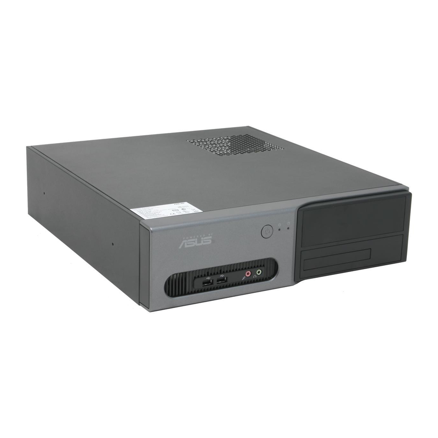
- Page 12 The ASUS Pundit-AE3 is an all-in-one barebone system with powerful and flexible features. The system comes in a stylish mini-tower casing, and powered by the ASUS motherboard that supports the AMD Athlon™ 64 FX/Athlon™ 64/Athlon™/ Sempron™ processor in the 754-pin package with 800 MHz FSB and up to 2 GB system memory.
- Page 13 The front panel includes the system and audio control buttons and LEDs. 3 3 3 3 3 2 2 2 2 2 1 1 1 1 1 4 4 4 4 4 7 7 7 7 7 6 6 6 6 6 5 5 5 5 5 1 .
-
Page 14: Other Devices
The system rear panel includes the power connector and several I/O ports that allow convenient connection of devices. 1 1 1 1 1 2 2 2 2 2 3 3 3 3 3 4 4 4 4 4 5 5 5 5 5 6 6 6 6 6 7 7 7 7 7 8 8 8 8 8... - Page 15 1 4 . 1 4 . 1 4 . 1 4 . 1 4 . M i c r o p h o n e p o r t M i c r o p h o n e p o r t M i c r o p h o n e p o r t M i c r o p h o n e p o r t M i c r o p h o n e p o r t...
- Page 16 Hard disk drive bays Hard disk drive lock Power supply unit PCI Express x1 slot PCI slots AGP slot 10. ASUS motherboard 11. Metal bracket lock 12. Socket 754 13. CPU fan and heatsink assembly (optional) 14. DIMM sockets 1 - 6...
- Page 17 This chapter provides step-by-step instructions on how to install components in the system. A S U S P u n d i t - A E 3 A S U S P u n d i t - A E 3 A S U S P u n d i t - A E 3 A S U S P u n d i t - A E 3 A S U S P u n d i t - A E 3...
-
Page 18: Before You Proceed
Before you proceed, make sure that you have all the components you plan to install in the system. Basic components to install Basic components to install Basic components to install Basic components to install Basic components to install Central processing unit (CPU) DDR Dual Inline Memory Module (DIMM) Expansion card(s) Hard disk drive... -
Page 19: Removing The System Cover
2.3.1 2.3.1 Removing the system cover Removing the system cover 2.3.1 2.3.1 2.3.1 Removing the system cover Removing the system cover Removing the system cover To remove the cover and metal chassis support: On the rear panel, locate the Remove the cover screws. two thumb screws that secure Keep the screws for later use. -
Page 20: Removing The Front Panel Assembly
2.3.2 2.3.2 2.3.2 Removing the front panel assembly Removing the front panel assembly Removing the front panel assembly 2.3.2 2.3.2 Removing the front panel assembly Removing the front panel assembly To remove the front panel assembly: Place the system vertically. Pull the hooks outward to release the front panel Locate the front panel... -
Page 21: Overview
2.4.1 2.4.1 Overview Overview 2.4.1 2.4.1 2.4.1 Overview Overview Overview The motherboard comes with a surface mount 754-pin Zero Insertion Force (ZIF) socket designed for the AMD Athlon™ 64 FX/Athlon™ 64/Sempron™ processor. The 128-bit-wide data paths of these processors can run applications faster than processors with only 32-bit or 64-bit wide data paths. -
Page 22: Cpu Fan And Heatsink Assembly Installation
Carefully insert the CPU to the socket until it fits in place. The CPU fits only in one correct orientation. Do not force the CPU into the socket to prevent bending the pins and damaging the CPU! When the CPU is in place, push down the socket lever to secure the CPU. - Page 23 Insert one retention clip hook to the hole at the other side of the retention module. Carefully press down the retention clip locking lever until the hook attaches to retention module hole. Install the second retention clip. Make sure that the retention clip locking levers are on opposite corners.
-
Page 24: Memory Configurations
The system motherboard comes with two Double Data Rate (DDR) Dual Inline Memory Module (DIMM) sockets. The following figure illustrates the location of the sockets: ® 184-pin DDR DIMM sockets 2.5.1 2.5.1 2.5.1 2.5.1 2.5.1 Memory configurations Memory configurations Memory configurations Memory configurations Memory configurations You may install up to 2 GB system memory using 256 MB, 512 MB, and... - Page 25 Supports one pair of modules inserted into the slots as one pair of Dual-channel memory configuration Visit the ASUS website (www.asus.com) for the latest DDR Qualified Vendors List. A S U S P u n d i t - A E 3...
-
Page 26: Installing A Dimm
2.5.2 2.5.2 2.5.2 Installing a DIMM Installing a DIMM Installing a DIMM 2.5.2 2.5.2 Installing a DIMM Installing a DIMM Make sure to unplug the power supply before adding or removing DIMMs or other system components. Failure to do so may cause severe damage to both the motherboard and the components. -
Page 27: Installing An Expansion Card
In the future, you may need to install expansion cards. The motherboard has two PCI, one PCI Express™ x1, and one AGP slots. The following sub-sections describe the slots and the expansion cards that they support. l o w p r o f i l e l o w p r o f i l e The system supports l o w p r o f i l e l o w p r o f i l e... -
Page 28: Expansion Card Installation
2.6.2 2.6.2 2.6.2 Expansion card installation Expansion card installation Expansion card installation 2.6.2 2.6.2 Expansion card installation Expansion card installation Make sure to unplug the power cord before adding or removing expansion cards. Failure to do so may cause you physical injury and damage the motherboard. - Page 29 Replace the expansion card lock to secure the card to the chassis. Standard interrupt assignments Standard interrupt assignments Standard interrupt assignments Standard interrupt assignments Standard interrupt assignments I R Q I R Q I R Q P r i o r i t y P r i o r i t y P r i o r i t y S t a n d a r d F u n c t i o n...
- Page 30 The system comes with a 5.25-inch drive bay for an optical drive. If you plan to install an IDE hard disk drive, set the optical drive as a slave device before installing it to the system. Refer to the optical drive documentation for details on how to set the drive as slave device.
- Page 31 Carefully push the optical drive all the way into the bay until the optical drive lock clicks. Connect a 4-pin power plug from the power supply unit to the power connector at the back of the drive. Uninstalling the optical drive Uninstalling the optical drive Uninstalling the optical drive Uninstalling the optical drive...
-
Page 32: Installing An Optical Drive
The system comes with two 3.5-inch drive bays (labeled 1 and 2) for installation of two Serial ATA hard disk drives or one IDE HDD (if you have installed an optical drive). 2.8.1 2.8.1 2.8.1 Hard disk drive bays Hard disk drive bays Hard disk drive bays 2.8.1 2.8.1... - Page 33 Connect one end of the supplied 7-pin SATA cable to the SATA connector at the back of the drive, then connect the other end to a SATA connector on the motherboard. See page 4-6 for the location of the SATA connectors.
-
Page 34: Ide Hard Disk Drive Installation
2.8.3 2.8.3 2.8.3 IDE hard disk drive installation IDE hard disk drive installation IDE hard disk drive installation 2.8.3 2.8.3 IDE hard disk drive installation IDE hard disk drive installation Set the IDE HDD as master device before connecting the IDE cable and power plug. -
Page 35: Replacing The Front Panel Assembly
After you install all the necessary components to the system, replace the covers following the instructions in this section. 2.9.1 2.9.1 2.9.1 Replacing the front panel assembly Replacing the front panel assembly Replacing the front panel assembly 2.9.1 2.9.1 Replacing the front panel assembly Replacing the front panel assembly If you installed an optical drive, you must remove the optical drive bay cover before you replace the front panel assembly. - Page 36 To replace the front panel assembly: Hook the hinge-like tabs to the holes on the right side of the chassis. H i n g e - l i k e t a b s H i n g e - l i k e t a b s H i n g e - l i k e t a b s H i n g e - l i k e t a b s H i n g e - l i k e t a b s...
-
Page 37: Replacing The System Cover
2.9.2 2.9.2 2.9.2 Replacing the system cover Replacing the system cover Replacing the system cover 2.9.2 2.9.2 Replacing the system cover Replacing the system cover To replace the metal chassis support: Reinstall the metal chassis support and the expansion card lock. - Page 38 You need to install the foot stands to place the system vertically on your desktop. To install the foot stands: Lay the system on its side on a flat, stable, and elevated surface, then locate two screw holes on the left side of the system. Extend the left side of the system at least 3 cm from the edge of surface to facilitate installation.
-
Page 39: To The Front Panel
The system’s power supply unit has a 115 V/230 V voltage selector switch located beside the power connector. Use this switch to select the appropriate system input voltage according to the voltage supply in your area. If the voltage supply in your area is 100-127 V, set the switch to 115 V. If the voltage supply in your area is 200-240 V, set the switch to 230 V. -
Page 40: To The Rear Panel
2.12.2 2.12.2 To the rear panel To the rear panel 2.12.2 2.12.2 2.12.2 To the rear panel To the rear panel To the rear panel P P P P P o w e r o u t l e t o w e r o u t l e t o w e r o u t l e t o w e r o u t l e t... - Page 41 This chapter helps you power up the system and install drivers and utilities from the support CD. A S U S P u n d i t - A E 3 A S U S P u n d i t - A E 3 A S U S P u n d i t - A E 3 A S U S P u n d i t - A E 3 A S U S P u n d i t - A E 3...
-
Page 42: Chapter 3: Getting Started
The support CD that came with the system package contains the drivers, software applications, and utilities that you can install to avail all system features. The contents of the support CD are subject to change at any time without notice. Visit the ASUS website(www.asus.com) for updates. 3.2.1 3.2.1 3.2.1... -
Page 43: Drivers Menu
3.2.2 3.2.2 3.2.2 Drivers menu Drivers menu Drivers menu 3.2.2 3.2.2 Drivers menu Drivers menu The drivers menu shows the available device drivers if the system detects installed devices. Install the necessary drivers to activate the devices. SiS760 Graphics Driver SiS760 Graphics Driver SiS760 Graphics Driver SiS760 Graphics Driver... -
Page 44: Utilities Menu
ASUS Update ASUS Update ASUS Update ASUS Update The ASUS Update utility allows you to update the motherboard BIOS in a Windows ® environment. This utility requires an Internet connection either through a network or an Internet Service Provider (ISP). See page 5-3 for details. -
Page 45: Asus Contact Information
C o n t a c t C o n t a c t C o n t a c t tab to display the ASUS contact information. You can also find this information on the inside front cover of this user guide. - Page 46 Technical support form Technical support form Technical support form Technical support form Technical support form Displays the ASUS Technical Support Request Form that you have to fill out when requesting technical support. 3 - 6 3 - 6 3 - 6...
-
Page 47: Text Format
Filelist Filelist Filelist Filelist Filelist Displays the contents of the support CD and a brief description of each in text format. A S U S P u n d i t - A E 3 A S U S P u n d i t - A E 3 A S U S P u n d i t - A E 3 A S U S P u n d i t - A E 3 A S U S P u n d i t - A E 3... -
Page 48: Soundmax ® 4 Xl Software
3.3.1 3.3.1 SoundMAX SoundMAX ® ® ® ® ® 4 XL software 4 XL software 3.3.1 3.3.1 3.3.1 SoundMAX SoundMAX SoundMAX 4 XL software 4 XL software 4 XL software The ADI AD1888 AC ‘97 audio CODEC provides 6-channel audio capability through the SoundMAX ®... - Page 49 Using the Audio Wizard Using the Audio Wizard Using the Audio Wizard Using the Audio Wizard Using the Audio Wizard The Audio Wizard helps you set up the speaker, microphone, and other aduio settings for optimal audio performance. To configure the speakers and microphone using the Audio Wizard: Click the wizard icon from the SoundMAX...
- Page 50 Adjust the microphone Click N e x t N e x t N e x t when finished. N e x t N e x t volume, then click T e s t T e s t T e s t to T e s t T e s t After adjusting the audio...
- Page 51 General The G e n e r a l G e n e r a l G e n e r a l G e n e r a l tab allows you to select and adjust the playback and G e n e r a l recording devices, and the SoundMAX application preferences.
-
Page 52: Midi Music Synthesizer
MIDI Music Synthesizer The M I D I M u s i c S y n t h e s i z e r M I D I M u s i c S y n t h e s i z e r M I D I M u s i c S y n t h e s i z e r M I D I M u s i c S y n t h e s i z e r tab allows you to set the MIDI and M I D I M u s i c S y n t h e s i z e r... -
Page 53: Asus Pc Probe Ii
S t a r t > A l l A l l A l l Programs > ASUS Programs > ASUS Programs > ASUS > PC Probe II PC Probe II PC Probe II. The PC Probe II main window appears. PC Probe II Programs > ASUS Programs >... - Page 54 Sensor alert When a system sensor detects a problem, the main window right handle turns red. Refer to the illustration below. When displayed, the monitor panel for that sensor also turns red. Refer to the M o n i t o r p a n e l s M o n i t o r p a n e l s M o n i t o r p a n e l s M o n i t o r p a n e l s...
- Page 55 Hardware monitor panels Hardware monitor panels Hardware monitor panels Hardware monitor panels Hardware monitor panels The hardware monitor panels display the current value of a system sensor such as fan rotation, CPU temperature, and voltages. The hardware monitor panels come in two display modes: hexagonal (large) and rectangular (small).
- Page 56 M o n i t o r i n g s e n s o r a l e r t M o n i t o r i n g s e n s o r a l e r t M o n i t o r i n g s e n s o r a l e r t M o n i t o r i n g s e n s o r a l e r t M o n i t o r i n g s e n s o r a l e r t...
- Page 57 DMI browser DMI browser DMI browser DMI browser DMI browser Click to display the DMI (Desktop Management Interface) browser. This browser displays various desktop and system information. Click the D M I I n f o r m a t i o n D M I I n f o r m a t i o n plus sign (+) before D M I I n f o r m a t i o n D M I I n f o r m a t i o n...
- Page 58 U s a g e U s a g e U s a g e U s a g e U s a g e The U s a g e U s a g e U s a g e U s a g e U s a g e browser displays real-time information on the CPU, hard disk drive space, and memory usage.
- Page 59 H a r d d i s k d r i v e s p a c e u s a g e H a r d d i s k d r i v e s p a c e u s a g e H a r d d i s k d r i v e s p a c e u s a g e H a r d d i s k d r i v e s p a c e u s a g e H a r d d i s k d r i v e s p a c e u s a g e...
-
Page 60: Cool 'N' Quiet!™ Technology
3.3.3 3.3.3 3.3.3 Cool ‘n’ Quiet!™ Technology Cool ‘n’ Quiet!™ Technology Cool ‘n’ Quiet!™ Technology 3.3.3 3.3.3 Cool ‘n’ Quiet!™ Technology Cool ‘n’ Quiet!™ Technology • Make sure to install the Cool ‘n’ Quiet!™ driver and application before using this feature. •... - Page 61 Launching the Cool ‘n’ Quiet!™ application Launching the Cool ‘n’ Quiet!™ application Launching the Cool ‘n’ Quiet!™ application Launching the Cool ‘n’ Quiet!™ application Launching the Cool ‘n’ Quiet!™ application The motherboard support CD includes the Cool ‘n’ Quiet!™ software application that enables you to view your system’s real-time CPU frequency and core voltage.
- Page 62 3 - 2 2 3 - 2 2 3 - 2 2 3 - 2 2 3 - 2 2 C h a p t e r 3 : G e t t i n g s t a r t e d C h a p t e r 3 : G e t t i n g s t a r t e d C h a p t e r 3 : G e t t i n g s t a r t e d C h a p t e r 3 : G e t t i n g s t a r t e d...
- Page 63 This chapter gives information about the motherboard that comes with the system. This chapter includes the motherboard layout, jumper settings, and connector locations. A S U S P u n d i t - A E 3 A S U S P u n d i t - A E 3 A S U S P u n d i t - A E 3 A S U S P u n d i t - A E 3 A S U S P u n d i t - A E 3...
-
Page 64: Chapter 4: Motherboard Info
Motherboard layout Motherboard layout Motherboard layout Motherboard layout Motherboard layout 19.9cm (7.8in) ® PS/2KBMS T: Mouse CHA_FAN CPU_FAN B: Keyboard ATX12V COM1 USB12 USBPW34 USBPW12 Bottom: Top: USB34 RJ-45 760GX Top:Line In Center:Line Out Below:Mic In RTL8201CL PCIEX1_1 Accelerated Graphics Port (AGP) BIOS 965L PCI1... -
Page 65: Jumpers
1 . 1 . C l e a r R T C R A M ( C L R T C 1 ) C l e a r R T C R A M ( C L R T C 1 ) C l e a r R T C R A M ( C L R T C 1 ) C l e a r R T C R A M ( C L R T C 1 ) C l e a r R T C R A M ( C L R T C 1 ) - Page 66 2 . 2 . U S B d e v i c e w a k e - u p ( 3 - p i n U S B P W 1 2 , U S B P W 3 4 , U S B d e v i c e w a k e - u p ( 3 - p i n U S B P W 1 2 , U S B P W 3 4 , U S B d e v i c e w a k e - u p ( 3 - p i n U S B P W 1 2 , U S B P W 3 4 , U S B d e v i c e w a k e - u p ( 3 - p i n U S B P W 1 2 , U S B P W 3 4 ,...
-
Page 67: Connectors
4.3.1 4.3.1 Rear panel connectors Rear panel connectors 4.3.1 4.3.1 4.3.1 Rear panel connectors Rear panel connectors Rear panel connectors Refer to section “1.3 Rear panel” for a description of the rear panel I/O ports. 4.3.2 4.3.2 4.3.2 Internal connectors Internal connectors Internal connectors 4.3.2... -
Page 68: Hard Disk Drives
2 . 2 . S e r i a l A T A c o n n e c t o r s ( 7 - p i n S A T A 1 , S A T A 2 ) S e r i a l A T A c o n n e c t o r s ( 7 - p i n S A T A 1 , S A T A 2 ) S e r i a l A T A c o n n e c t o r s ( 7 - p i n S A T A 1 , S A T A 2 ) S e r i a l A T A c o n n e c t o r s ( 7 - p i n S A T A 1 , S A T A 2 ) - Page 69 4 . 4 . U S B c o n n e c t o r s ( 1 0 - 1 p i n U S B 5 6 , U S B 7 8 ) U S B c o n n e c t o r s ( 1 0 - 1 p i n U S B 5 6 , U S B 7 8 ) U S B c o n n e c t o r s ( 1 0 - 1 p i n U S B 5 6 , U S B 7 8 ) U S B c o n n e c t o r s ( 1 0 - 1 p i n U S B 5 6 , U S B 7 8 ) U S B c o n n e c t o r s ( 1 0 - 1 p i n U S B 5 6 , U S B 7 8 )
- Page 70 6 . 6 . A T X p o w e r c o n n e c t o r s ( 2 4 - p i n A T X P W R , 4 - p i n A T X 1 2 V ) A T X p o w e r c o n n e c t o r s ( 2 4 - p i n A T X P W R , 4 - p i n A T X 1 2 V ) A T X p o w e r c o n n e c t o r s ( 2 4 - p i n A T X P W R , 4 - p i n A T X 1 2 V ) A T X p o w e r c o n n e c t o r s ( 2 4 - p i n A T X P W R , 4 - p i n A T X 1 2 V )
- Page 71 8 . 8 . G A M E / M I D I p o r t c o n n e c t o r ( 1 6 - 1 p i n G A M E ) G A M E / M I D I p o r t c o n n e c t o r ( 1 6 - 1 p i n G A M E ) G A M E / M I D I p o r t c o n n e c t o r ( 1 6 - 1 p i n G A M E ) G A M E / M I D I p o r t c o n n e c t o r ( 1 6 - 1 p i n G A M E ) G A M E / M I D I p o r t c o n n e c t o r ( 1 6 - 1 p i n G A M E )
- Page 72 1 0 . 1 0 . 1 0 . D i g i t a l a u d i o c o n n e c t o r ( 4 - 1 p i n S P D I F _ O U T ) D i g i t a l a u d i o c o n n e c t o r ( 4 - 1 p i n S P D I F _ O U T ) D i g i t a l a u d i o c o n n e c t o r ( 4 - 1 p i n S P D I F _ O U T ) D i g i t a l a u d i o c o n n e c t o r ( 4 - 1 p i n S P D I F _ O U T )
- Page 73 • A T X p o w e r b u t t o n / s o f t - o f f b u t t o n ( 2 - p i n P W R B T N ) A T X p o w e r b u t t o n / s o f t - o f f b u t t o n ( 2 - p i n P W R B T N ) A T X p o w e r b u t t o n / s o f t - o f f b u t t o n ( 2 - p i n P W R B T N ) A T X p o w e r b u t t o n / s o f t - o f f b u t t o n ( 2 - p i n P W R B T N )
- Page 74 4 - 1 2 4 - 1 2 4 - 1 2 4 - 1 2 4 - 1 2 C h a p t e r 4 : M o t h e r b o a r d i n f o C h a p t e r 4 : M o t h e r b o a r d i n f o C h a p t e r 4 : M o t h e r b o a r d i n f o C h a p t e r 4 : M o t h e r b o a r d i n f o...
- Page 75 This chapter tells how to change system settings through the BIOS Setup menus and describes the BIOS parameters. A S U S P u n d i t - A E 3 A S U S P u n d i t - A E 3 A S U S P u n d i t - A E 3 A S U S P u n d i t - A E 3 A S U S P u n d i t - A E 3...
-
Page 76: Chapter 5: Bios Setup
ASUS EZ Flash utility ASUS EZ Flash utility The ASUS EZ Flash feature allows you to update the BIOS without having to go through the long process of booting from a floppy disk and using a DOS-based utility. The EZ Flash utility is built-in the BIOS chip so it is accessible by pressing <Alt>... -
Page 77: Asus Crashfree Bios 2 Utility
ASUS CrashFree BIOS 2 utility ASUS CrashFree BIOS 2 utility The ASUS CrashFree BIOS 2 is an auto recovery tool that allows you to restore the BIOS file when it fails or gets corrupted during the updating process. You can update a corrupted BIOS file using the motherboard support CD that contains the original or updated BIOS file. -
Page 78: Asus Update Utility
ASUS Update utility 5.1.3 5.1.3 ASUS Update utility ASUS Update utility The ASUS Update is a utility that allows you to manage, save, and update the motherboard BIOS in Windows ® environment. The ASUS Update utility allows you to: • Save the current BIOS file •... - Page 79 A S U S U p d a t e A S U S U p d a t e A S U S U p d a t e. The ASUS Update main window appears. A S U S U p d a t e...
- Page 80 A S U S U p d a t e A S U S U p d a t e A S U S U p d a t e. The ASUS Update main window appears. A S U S U p d a t e...
-
Page 81: Bios Setup Program
• Visit the ASUS website (www.asus.com) to download the latest BIOS file for this motherboard. A S U S P u n d i t - A E 3... -
Page 82: Bios Menu Screen
5.2.1 5.2.1 5.2.1 BIOS menu screen BIOS menu screen BIOS menu screen 5.2.1 5.2.1 BIOS menu screen BIOS menu screen M e n u i t e m s M e n u i t e m s M e n u i t e m s M e n u i t e m s M e n u i t e m s M e n u b a r... -
Page 83: Menu Items
5.2.4 5.2.4 5.2.4 Menu items Menu items Menu items 5.2.4 5.2.4 Menu items Menu items The highlighted item on the menu Use [ENTER], [TAB] bar displays the specific items for System Time [11:51:19] or [SHIFT-TAB] to System Date [Thu 06/10/2004] select a field. -
Page 84: System Time
When you enter the BIOS Setup program, the Main menu screen appears, giving you an overview of the basic system information. Refer to section “5.2.1 BIOS menu screen” for information on the menu screen items and how to navigate through them. System Time [11:51:19] Use [ENTER], [TAB] or... -
Page 85: Primary, Secondary Third, And Fourth Ide Master/Slave
5.3.4 5.3.4 5.3.4 Primary, Secondary Third, and Fourth Primary, Secondary Third, and Fourth Primary, Secondary Third, and Fourth 5.3.4 5.3.4 Primary, Secondary Third, and Fourth Primary, Secondary Third, and Fourth IDE Master/Slave IDE Master/Slave IDE Master/Slave IDE Master/Slave IDE Master/Slave While entering Setup, the BIOS automatically detects the presence of IDE devices. -
Page 86: Onboard Pci Sata Controller
PIO Mode [4] PIO Mode [4] PIO Mode [4] PIO Mode [4] PIO Mode [4] Selects the PIO mode. Configuration options: [Auto] [0] [1] [2] [3] [4] DMA Mode [Auto] DMA Mode [Auto] DMA Mode [Auto] DMA Mode [Auto] DMA Mode [Auto] Selects the DMA mode. -
Page 87: Cpu Configuration
The Advanced menu items allow you to change the settings for the CPU and other system devices. Take caution when changing the settings of the Advanced menu items. Incorrect field values can cause the system to malfunction. CPU Configuration Configure CPU. Chipset Onboard Devices Configuration PCI PnP... -
Page 88: Chipset
Memory Configuration Memory Configuration Memory Configuration Memory Configuration Memory Configuration Allows you to set memory parameters to enhance system performance. Memory Configuration Enable Bank Memory Interleaving. Bank Interleaving [Auto] Burst Length [4 Beats] Memclock Mode [Auto] Memory CLK : 166 MHz CAS Latency : 2.5 TRCD... - Page 89 AGP Configuration AGP Configuration AGP Configuration AGP Configuration AGP Configuration Allows you to set the AGP parameters. AGP Configuration Select the size of mapped memory for AGP Aperture Size [64MB] graphic data. Graphic Adapter Priority [AGP/Int-VGA] AGP FAST WRITE [Disabled] Select AGP 3.0 Data Ratio [8X] Share Memory...
- Page 90 HyperTransport Configuration HyperTransport Configuration HyperTransport Configuration HyperTransport Configuration HyperTransport Configuration HyperTransport Configuration Host Link_width_out x Link_width_in HT Width [ 8x16 BIT] HT Speed [800 MHz] HT Width [8x16 BIT] Sets the HyperTransport data width. Configuration options: [8x8 BIT] [16x16 BIT] [16x8 BIT] [8x16 BIT] HT Speed [800 MHz] Sets the HyperTransport data speed.
-
Page 91: Onboard Devices Configuration
5.4.3 5.4.3 5.4.3 5.4.3 5.4.3 Onboard Devices Configuration Onboard Devices Configuration Onboard Devices Configuration Onboard Devices Configuration Onboard Devices Configuration Onboard AC97 Audio DEVICE [Enabled] Enable/Disable the Onboard SiS190 LAN DEVICE [Enabled] AC97 CODEC. SiS190 LAN Boot ROM [Disabled] USB Configuration Serial Port1 Address [3F8/IRQ4] Serial Port2 Address... - Page 92 The USB Devices Enabled items show the auto-detected values. If no USB N o n e N o n e device is detected, the item shows N o n e N o n e N o n e. OnBoard SiS USB 1.1 Device [Enabled] Allows you to enable or disable the onboard SiS USB 1.1 device.
- Page 93 Parallel Port Mode [ECP] Parallel Port Mode [ECP] Parallel Port Mode [ECP] Parallel Port Mode [ECP] Parallel Port Mode [ECP] P a r a l l e l P o r t P a r a l l e l P o r t Allows you to select the Parallel Port mode.
-
Page 94: Pci Pnp
5.4.4 5.4.4 5.4.4 PCI PnP PCI PnP PCI PnP 5.4.4 5.4.4 PCI PnP PCI PnP The PCI PnP menu items allow you to change the advanced settings for PCI/PnP devices. The menu includes setting IRQ and DMA channel resources for either PCI/PnP or legacy ISA devices, and setting the memory size block for legacy ISA devices. - Page 95 PCI IDE BusMaster [Enabled] PCI IDE BusMaster [Enabled] PCI IDE BusMaster [Enabled] PCI IDE BusMaster [Enabled] PCI IDE BusMaster [Enabled] Allows BIOS to use PCI bus mastering when reading/writing to IDE devices. Configuration options: [Disabled] [Enabled] OffBoard PCI/ISA IDE Card [Auto] OffBoard PCI/ISA IDE Card [Auto] OffBoard PCI/ISA IDE Card [Auto] OffBoard PCI/ISA IDE Card [Auto]...
-
Page 96: Suspend Mode
The Power menu items allow you to change the settings for the Advanced Power Management (APM) and Advanced Configuration and Power Interface (ACPI). Select an item then press <Enter> to display the configuration options. Suspend Mode [Auto] Select the ACPI state Repost Video on S3 Resume [No] used for System... -
Page 97: Apm Configuration
5.5.5 5.5.5 5.5.5 APM Configuration APM Configuration APM Configuration 5.5.5 5.5.5 APM Configuration APM Configuration Power Button Mode [On/Off] Go into On/Off, Restore on AC Power Loss [Power Off] Standby or Suspend Resume on Ring [Disabled] when Power Button is Power Up By PCI Device [Disabled] pressed. - Page 98 Resume On PS2 Mouse [Disabled] Resume On PS2 Mouse [Disabled] Resume On PS2 Mouse [Disabled] Resume On PS2 Mouse [Disabled] Resume On PS2 Mouse [Disabled] When set to [Enabled], this parameter allows you to use the PS/2 mouse to turn on the system. This feature requires an ATX power supply that provides at least 1A on the +5VSB lead.
-
Page 99: Hardware Monitor
Smart Fan Control [Enabled] Smart Fan Control [Enabled] Smart Fan Control [Enabled] Allows you to enable or disable the ASUS Smart Fan feature that smartly adjusts the fan speeds for more efficient system operation. Configuration options: [Disabled] [Enabled] A S U S P u n d i t - A E 3... -
Page 100: Boot Device Priority
The Boot menu items allow you to change the system boot options. Select an item then press <Enter> to display the sub-menu. Boot Settings Specifies the Boot Device Priority sequence Boot Device Priority Boot Settings Configuration Security 5.6.1 5.6.1 5.6.1 Boot Device Priority Boot Device Priority Boot Device Priority... -
Page 101: Boot Settings Configuration
This allows you to enable or disable the full screen logo display feature. Configuration options: [Disabled] [Enabled] Set this item to [Enabled] to use the ASUS MyLogo™ feature. Add On ROM Display Mode [Keep Current] Add On ROM Display Mode [Keep Current]... -
Page 102: Security
5.6.3 5.6.3 5.6.3 Security Security Security 5.6.3 5.6.3 Security Security The Security menu items allow you to change the system security settings. Select an item then press <Enter> to display the configuration options. Security Settings <Enter> to change password. Supervisor Password : Not Installed <Enter>... - Page 103 After you have set a supervisor password, the other items appear to allow you to change other security settings. Security Settings Supervisor Password : Not Installed User Password : Not Installed Change Supervisor Password User Access Level [Full Access] Change User Password Clear User Password Password Check [Setup]...
- Page 104 To change the user password, follow the same steps as in setting a user password. Clear User Password Clear User Password Clear User Password Clear User Password Clear User Password Select this item to clear the user password. Password Check [Setup] Password Check [Setup] Password Check [Setup] Password Check [Setup]...
-
Page 105: Exit Menu
The Exit menu items allow you to load the optimal or failsafe default values for the BIOS items, and save or discard your changes to the BIOS items. Exit Options Exit & Save Changes Exit & Discard Changes Discard Changes Load Setup Defaults Pressing <Esc>... - Page 106 Load Setup Defaults Load Setup Defaults Load Setup Defaults Load Setup Defaults Load Setup Defaults This option allows you to load the default values for each of the parameters on the Setup menus. When you select this option or if you press <F5>, a confirmation window appears.