
Related Manuals for Dell EMC PowerEdge MX750c


Summary of Contents for Dell EMC PowerEdge MX750c
- Page 1 Dell EMC PowerEdge MX750c Installation and Service Manual Part Number: E04B Regulatory Type: E04B003 May 2021 Rev. A00...
- Page 2 A WARNING indicates a potential for property damage, personal injury, or death. © 2021 Dell Inc. or its subsidiaries. All rights reserved. Dell, EMC, and other trademarks are trademarks of Dell Inc. or its subsidiaries. Other trademarks may be trademarks of their respective owners.
-
Page 3: Table Of Contents
Contents Chapter 1: About this document....................6 Chapter 2: Dell EMC PowerEdge MX750c system overview............7 Front view of the system..............................8 Inside the system.................................9 Locating the Express Service Code and Service Tag....................10 System information label..............................11 Chapter 3: Initial system setup and configuration................ 15 Setting up the system...............................15... - Page 4 Installing the drive carrier............................33 Removing the drive from the drive carrier......................34 Installing the drive into the drive carrier........................35 Drive backplane..................................36 Drive backplane details.............................. 36 Removing drive backplane............................37 Installing drive backplane............................38 Cable routing..................................40 Drive cage................................... 47 Removing the drive cage............................47 Installing the drive cage.............................
- Page 5 Power button LED................................106 System health and system ID indicator codes......................106 Drive indicator codes..............................107 Using system diagnostics...............................107 Dell Embedded System Diagnostics........................107 Chapter 9: Getting help......................109 Recycling or End-of-Life service information......................109 Contacting Dell Technologies............................109 Accessing system information by using QRL......................109 Quick Resource Locator for PowerEdge MX750c system................110...
-
Page 6: Chapter 1: About This Document
About this document This document provides an overview about the system, information about installing and replacing components, technical specifications, diagnostic tools, and guidelines to be followed while installing certain components. About this document... -
Page 7: Chapter 2: Dell Emc Poweredge Mx750C System Overview
NOTE: The Dell EMC PowerEdge MX750c is compatible with the Dell EMC PowerEdge MX7000 enclosure running OME-Modular 1.30 or higher. For more information about the enclosure, see the Installation and Service Manual for the PowerEdge MX7000 at www.dell.com/poweredgemanuals. -
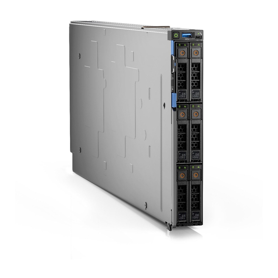
Page 8: Front View Of The System
5. Release handle button 6. Information tag 7. System health and System ID indicator 8. Power button NOTE: For more information, see the Dell EMC PowerEdge MX750c Technical Specifications on the product documentation page. Dell EMC PowerEdge MX750c system overview... -
Page 9: Inside The System
8. System health and System ID indicator 9. Power button Inside the system NOTE: Components that are hot swappable have orange touch points and the components that are not hot swappable have blue touch points. Dell EMC PowerEdge MX750c system overview... -
Page 10: Locating The Express Service Code And Service Tag
The Mini Enterprise Service Tag (MEST) label is located on the rear of the system that includes Service Tag (ST), Express Service Code (Exp Svc Code), and Manufacture Date (Mfg. Date). The Exp Svc Code is used by Dell EMC to route support calls to the appropriate personnel. -
Page 11: System Information Label
System information label Figure 5. Mechanical overview Dell EMC PowerEdge MX750c system overview... - Page 12 Figure 6. Memory overview Dell EMC PowerEdge MX750c system overview...
- Page 13 Figure 7. System board Figure 8. Jumper settings Dell EMC PowerEdge MX750c system overview...
- Page 14 Figure 9. Quick Resource Locator Figure 10. System tasks Dell EMC PowerEdge MX750c system overview...
-
Page 15: Chapter 3: Initial System Setup And Configuration
Initial system setup and configuration This section describes the tasks for initial setup and configuration of the Dell EMC system. The section also provides general steps to set up the system and the reference guides for detailed information. Topics: •... -
Page 16: Options To Log In To Idrac
Ensure that you change the default username and password after setting up the iDRAC IP address. For more information about logging in to the iDRAC and iDRAC licenses, see the latest Integrated Dell Remote Access Controller User's Guide at www.dell.com/idracmanuals. -
Page 17: Resources To Install Operating System
NOTE: The Intel Quick Assist Technology (QAT) on the Dell EMC PowerEdge MX750c system is supported with chipset integration and is enabled through an optional license. The license files are enabled on the sleds through iDRAC. For more information about drivers, documentation, and white papers on the Intel QAT, see https://01.org/intel-quickassist-... -
Page 18: Options To Download And Install Os Drivers
Ensure that you clear the web browser cache before downloading the drivers and firmware. Steps 1. Go to www.dell.com/support/drivers. 2. Enter the Service Tag of the system in the Enter a Dell Service Tag, Dell EMC Product ID or Model field, and then press Enter. NOTE: If you do not have the Service Tag, click Browse all products, and navigate to your product. -
Page 19: Chapter 4: Minimum To Post And System Management Configuration Validation
Minimum to POST and system management configuration validation This section describes the minimum to POST system requirement and system management configuration validation of the Dell EMC system. Topics: • Minimum configuration to POST • Configuration validation Minimum configuration to POST The components listed below are the minimum configuration to POST: ●... -
Page 20: Error Messages
Table 5. Configuration validation error (continued) Error Description Possible cause and Example recommendations Comm Error A configuration element is not responding System management Comm Error: Backplane 2 to iDRAC using the management interface sideband communication while running an inventory check. Unplug AC Power, reseat the element and replace the element if the problem... -
Page 21: Chapter 5: Installing And Removing System Components
Damage due to servicing that is not authorized by Dell is not covered by your warranty. Read and follow the safety instructions that are shipped with your product. -
Page 22: Before Working Inside Your System
Before working inside your system Prerequisites Follow the safety guidelines listed in the Safety instructions. Steps 1. Power off the sled. 2. Remove the sled from the enclosure. 3. If applicable install the I/O connector cover. CAUTION: To prevent damage to the I/O connectors on the system, ensure that you cover the connectors when you remove the system from the enclosure. - Page 23 NOTE: Support the system with both hands while sliding it out of the enclosure. NOTE: Removing the sled with the enclosure powered on is supported if you shut down the sled before removal. Figure 11. Removing the sled from enclosure 3.
-
Page 24: Installing The Sled Into Enclosure
NOTE: The color of the I/O connector cover may differ. CAUTION: If you are permanently removing the sled, install a sled blank promptly. Operating the enclosure without a blank, for an extended time can result in overheating or performance loss. Next steps Install the sled. -
Page 25: Sled Cover
Figure 14. Installing the sled into enclosure Next steps 1. Power on the sled. Sled cover Removing the sled cover Prerequisites 1. Follow the safety guidelines listed in the Safety instructions. 2. Power off the sled. Remove the sled from the enclosure. -
Page 26: Installing The Sled Cover
Figure 15. Removing the sled cover Next steps Replace the sled cover. Installing the sled cover Prerequisites 1. Follow the safety guidelines listed in the Safety instructions. 2. Ensure that all internal cables are connected and routed properly, and no tools or extra parts are left inside the system. Steps 1. - Page 27 Figure 16. Installing the sled cover Next steps 1. Follow the procedure listed in After working inside your system. Installing and removing system components...
-
Page 28: Air Shroud
Air shroud Removing the air shroud Prerequisites CAUTION: Never operate your system with the air shroud removed. The system may get overheated quickly, resulting in shutdown of the system and loss of data. 1. Follow the safety guidelines listed in the Safety instructions. - Page 29 Figure 18. Installing the air shroud Next steps 1. Follow the procedure listed in After working inside your system. Installing and removing system components...
-
Page 30: Processor And Memory Module Blank
Processor and memory module blank Removing the processor and memory module blank Prerequisites 1. Follow the safety guidelines listed in the Safety instructions. 2. Follow the procedure listed in Before working inside your system. Steps 1. To release the processor and memory module blank from the socket, simultaneously press the ejectors on both ends of the memory module socket to fully open. -
Page 31: Drives
Figure 20. Installing the processor and memory module blank 2. Align the edges of the processor and memory module blank with the alignment key of the memory module socket, and insert the blank in the socket. 3. Press the blank with your thumbs until the ejectors firmly click into place. Next steps 1. -
Page 32: Installing A Drive Blank
Figure 21. Removing drive blank Next steps Install a drive replace the drive blank. Installing a drive blank Prerequisites 1. Follow the safety guidelines listed in the Safety instructions. Steps Insert the drive blank into the drive slot until the release button clicks into place. Figure 22. -
Page 33: Installing The Drive Carrier
CAUTION: Before attempting to remove or install a drive while the system is running, see the documentation for the storage controller card to ensure that the host adapter is configured correctly to support drive removal and installation. CAUTION: To prevent data loss, ensure that the operating system on the system supports drive installation. See the documentation supplied with your operating system. -
Page 34: Removing The Drive From The Drive Carrier
NOTE: Ensure that the drive carrier's release handle is in the open position before inserting the carrier into the slot. 1. Follow the safety guidelines listed in the Safety instructions. 2. Remove the drive carrier or remove the drive blank when you want to assemble the drives in to the system. Steps 1. -
Page 35: Installing The Drive Into The Drive Carrier
Figure 25. Removing a drive from drive carrier Next steps Replace the drive into the drive carrier. Installing the drive into the drive carrier Prerequisites 1. Follow the safety guidelines listed in the Safety instructions. Remove the drive blank. NOTE: When installing a drive into the drive carrier, ensure that the screws are torqued to 4 in-lbs. -
Page 36: Drive Backplane
Figure 26. Installing a drive into drive carrier Next steps Install the drive carrier. Drive backplane Drive backplane details Depending on the configuration, your system supports: ● 2.5-inch (x6) Universal backplane ● 2.5-inch (x6) SAS/SATA backplane ● 2.5-inch (x4) Universal backplane Figure 27. -
Page 37: Removing Drive Backplane
Figure 28. 6 x 2.5-inch SAS/SATA backplane 1. BP_DST_SA1 (SAS/SATA cable connector) 2. BP_PWR_1 (Power cable connector) Figure 29. 4 x 2.5-inch universal backplane 1. BP_PWR_1 (Power cable connector) 2. BP_DST_PB1 (PCIe cable connector) 3. BP_DST_SA1 (SAS/SATA cable connector) 4. BP_DST_PA1 (PCIe cable connector ) Removing drive backplane Prerequisites CAUTION:... -
Page 38: Installing Drive Backplane
Figure 30. Removing drive backplane Next steps Replace the drive backplane. Installing drive backplane Prerequisites 1. Follow the safety guidelines listed in Safety instructions 2. Follow the procedure listed in Before working inside the system. 3. Remove all the drives. Steps 1. - Page 39 Figure 31. Installing drive backplane Next steps 1. Connect the incoming power cable to the backplane and then verify both power and signal cable connections are fully seated to the backplane and system board. 2. Connect the integrated cable to the backplane and system board if there is no PERC card installed in the system. Install all the drives.
-
Page 40: Cable Routing
Cable routing Figure 32. SATA/PCIe cabling diagram of configuration 3 - 6 x 2.5-inch Universal backplane with on board SATA + on board PCIe Table 8. Connector descriptions for on board SATA + on board PCIe From BP_PWR_1 (backplane power connector) SIG_PWR_0 (system board power connector) BP_DST_PA1 (backplane PCIe 1 connector, cable marking BP SL1_CPU1_PA1 (signal connector on the system board, cable... - Page 41 Figure 33. PCIe cabling diagram of configuration 4 - 6 x 2.5-inch Universal backplane with H755 MX Table 9. Connector descriptions for PCIe with H755 MX From BP_PWR_1 (backplane power connector) SIG_PWR_0 (system board power connector) BP_DST_PA1 (backplane PCIe 1 connector, cable marking BP CTRL_SRC_PA1 (PCIe connector of H755 MX controller card, PA1) cable marking CTRL_PA1)
- Page 42 Table 10. Connector descriptions for on board SATA From BP_PWR_1 (backplane power connector) SIG_PWR_0 (system board power connector) BP_DST_SA1 (backplane SATA connector, cable marking BP SL6_PCH_SA1 (signal connector on the system board, cable SA1) marking MB SL6) Figure 35. SAS cabling diagram of configuration 6 - 6 x 2.5-inch SAS/SATA backplane with HBA350i MX Table 11.
- Page 43 Table 12. Connector descriptions for SAS with H755 MX From BP_PWR_1 (backplane power connector) SIG_PWR_0 (system board power connector) BP_DST_SA1 (backplane SAS connector, cable marking BP CTRL_SRC_SA1 (SAS connector of H755 MX controller card, SA1) cable marking CTRL_SA1) Figure 37. SAS cabling diagram of configuration 7 - 6 x 2.5-inch SAS/SATA backplane with H745P MX (Jumbo PERC) Table 13.
- Page 44 Figure 38. SAS/PCIe cabling diagram of configuration 9 - 4 x 2.5-inch Universal backplane with HBA350i MX + on board PCIe Table 14. Connector descriptions for SAS with HBA350i MX+ on board PCIe From BP_PWR_1 (backplane power connector) SIG_PWR_0 (system board power connector) BP_DST_PA1 (backplane PCIe 1 connector, cable marking SL1_CPU1_PA1 (signal connector on the system board, cable BP_PA1)
- Page 45 Table 15. Connector descriptions for SAS with H755 MX+ on board PCIe From BP_PWR_1 (backplane power connector) SIG_PWR_0 (system board power connector) BP_DST_PA1 (backplane PCIe 1 connector, cable marking SL1_CPU1_PA1 (signal connector on the system board, cable BP_PA1) marking MB SL1) BP_DST_SA1 (backplane SAS connector, cable marking BP CTRL_SRC_SA1 (SAS connector of H755 MX controller card, SA1)
- Page 46 Figure 41. SATA/PCIe cabling diagram of configuration 11 - 4 x 2.5-inch Universal backplane with on board SATA + on board PCIe Table 17. Connector descriptions for on board SATA + on board PCIe From BP_PWR_1 (backplane power connector) SIG_PWR_0 (system board power connector) BP_DST_PA1 (backplane PCIe 1 connector, cable marking BP SL1_CPU1_PA1 (signal connector on the system board, cable PA1)
-
Page 47: Drive Cage
Table 18. Connector descriptions for PCIe with H755 MX From BP_PWR_1 (backplane power connector) SIG_PWR_0 (system board power connector) BP_DST_PA1 (backplane PCIe 1 connector, cable marking BP CTRL_SRC_PA1 (PCIe connector of H755 MX controller card, PA1) cable marking CTRL_PA1) BP_DST_PB1 (backplane PCIe 2 connector, cable marking BP CTRL_SRC_PA1 (PCIe connector of H755 MX controller card, PB1) cable marking CTRL_PA1) -
Page 48: Installing The Drive Cage
Figure 43. Removing the drive cage Next steps Replace the drive cage. Installing the drive cage Prerequisites 1. Follow the safety guidelines listed in the Safety instructions. 2. Follow the procedure listed in Before working inside your system. 3. Disconnect the drive backplane cables from the connectors on the system board. Steps 1. -
Page 49: Control Panel
Figure 44. Installing the drive cage Next steps Install the drive backplane. Install all the drives. 3. Follow the procedure listed in After working inside your system. Control panel Removing the control panel Prerequisites 1. Follow the safety guidelines listed in the Safety instructions. -
Page 50: Installing The Control Panel
Figure 45. Removing the control panel Next steps Replace the control panel. Installing the control panel Prerequisites 1. Follow the safety guidelines listed in the Safety instructions. 2. Follow the procedure listed in Before working inside your system. Remove all the drives. -
Page 51: System Memory
Figure 46. Installing the control panel Next steps Install the drive cage. Install all the drives. 3. Follow the procedure listed in After working inside your system. System memory System memory guidelines The PowerEdge MX750c system supports DDR4 registered DIMMs (RDIMMs), load reduced DIMMs (LRDIMMs), Intel Optane Data Center Persistent Memory Modules (DCPMMs). -
Page 52: General Memory Module Installation Guidelines
Figure 47. Memory sockets on the system board The following table shows the memory populations and operating frequencies for the supported configurations: Table 20. Supported memory matrix DIMM Type DIMM Ranking Capacity Operating Voltage Frequency (in MT/s) RDIMM 8 GB 1.2 V 3200 RDIMM... -
Page 53: Intel Optane Pmem 200 Series Installation Guidelines
○ For dual-processor systems, sockets A1 to A16 and sockets B1 to B16 are available. ● In Optimizer Mode, the DRAM controllers operate independently in the 64-bit mode and provide optimized memory performance. Table 21. Memory population rules Processor Configuration Memory population Memory population information... - Page 54 ● Populate Intel Optane PMem 200 Series in DIMM slot 1, unless Intel Optane PMem 200 Series is the only DIMM in that channel, and then populate in DIMM slot 0. For more information about the supported Intel Persistent Memory 200 series (BPS) configurations, see the Dell EMC Intel Persistent Memory 200 series (BPS) User's Guide at https://www.dell.com/support/home/products/server_int/...
- Page 55 Table 23. Intel Optane PMem 200 Series Configuration 1 - 4 x RDIMMs/ LRDIMMs, 4 x Intel Optane PMem 200 Series per processor (continued) Total No of Total No of 1 R/LRDIMM 1 Intel Total Standard Total PM Supported RDIMMs/ Intel Optane capacity (GB) Persistent...
- Page 56 Table 25. Intel Optane PMem 200 Series Configuration 3 - 8 x RDIMMs/ LRDIMMs, 1 x Intel Optane PMem 200 Series per processor (continued) Total No of Total No of 1 R/LRDIMM 1 Intel Total Standard Total PM Supported Modes RDIMMs / Intel Optane capacity (GB)
-
Page 57: Removing A Memory Module
Table 27. Intel Optane PMem 200 Series Configuration 5 - 8 x RDIMMs/ LRDIMMs, 8 x Intel Optane PMem 200 Series per processor (continued) Total No of Total No of 1 R/LRDIMM 1 Intel Total Standard Total PM Supported Modes RDIMMs / Intel Optane capacity (GB) -
Page 58: Installing A Memory Module
2. To release the memory module from the socket, simultaneously press the ejectors on both ends of the memory module socket to fully open. 3. Lift the memory module away from the system. Figure 48. Removing a memory module Next steps Replace the memory module. -
Page 59: Processor And Heat Sink Module
CAUTION: Do not apply pressure at the center of the memory module; apply pressure at both ends of the memory module evenly. 4. Press the memory module with your thumbs until the ejectors firmly click into place. When the memory module is properly seated in the socket, the levers on the memory module socket align with the levers on the other sockets that have memory modules installed. - Page 60 a. Loosen the first screw three turns. b. Loosen the screw diagonally opposite to the screw you loosened first. c. Repeat the procedure for the remaining two screws. d. Return to the first screw to loosen it completely. 2. Set the Anti-Tilt wires to the unlocked position (inward position). Figure 50.
-
Page 61: Removing The Processor From The Processor And Heat Sink Module
Figure 51. Removing a processor and heat sink module Next steps Remove the processor from the processor and heat sink module. Removing the processor from the processor and heat sink module Prerequisites WARNING: Remove the processor from the processor and heat sink module (PHM) only if you are replacing the processor or heat sink. - Page 62 3. Holding the processor by its edges, lift the processor away from the retaining clip, and then place the processor connector side down on the processor tray. Ensure pin 1 marks are aligned. Figure 52. Lift up the TIM break lever Figure 53.
-
Page 63: Installing The Processor Into A Processor And Heat Sink Module
Figure 54. Removing the processor retaining clip Next steps Replace the processor into a processor and heat sink module (PHM). Installing the processor into a processor and heat sink module Prerequisites 1. Follow the safety guidelines listed in Safety instructions. 2. - Page 64 Figure 55. Installing the processor carrier 3. Align the processor with processor retaining clip by using your fingers to press the retaining clip on all the four sides until it clicks into place. NOTE: Ensure that the processor is securely latched to the processor retaining clip. Figure 56.
- Page 65 Figure 57. Applying thermal grease CAUTION: Applying too much thermal grease can result in excess grease coming in contact with and contaminating the processor socket. NOTE: The thermal grease syringe is intended for single use only. Dispose of the syringe after you use it. 6.
-
Page 66: Installing The Processor And Heat Sink Module
NOTE: Ensure latching features on processor retaining clip and heat sink are aligned during assembly. Figure 59. Installing the heat sink onto the processor Next steps Install the processor and heat sink module. Install the air shroud. 3. Follow the procedure listed in After working inside your system. - Page 67 NOTE: Ensure that the processor and heat sink is held parallel to the system board to prevent damaging the components. Figure 60. Installing the processor and heat sink (PHM) 3. Set the Anti-Tilt wires to the locked position (outward position), and then using the Torx #T30 screwdriver, tighten the screws (8 in-lbf) on the heat sink in the order below: a.
-
Page 68: Perc Card
Figure 61. Set the Anti-Tilt wires to the locked position and tightening the screws Next steps Install the air shroud. 2. Follow the procedure listed in After working inside your system. PERC card Your system includes dedicated slots on the system board for PERC cards. Removing the PERC card Prerequisites 1. - Page 69 Figure 62. Removing the PERC card (HBA350i MX) Figure 63. Removing the PERC card (H755 MX) Next steps 1. Follow the procedure listed in After working inside your system. Installing and removing system components...
-
Page 70: Installing The Perc Card
Installing the PERC card Prerequisites 1. Follow the safety guidelines listed in Safety Instructions. 2. Follow the procedure listed in Before working inside your system. Steps 1. Pull the blue pull tag to raise the lever up on the PERC card. 2. -
Page 71: Removing The Jumbo Perc Card
Figure 65. Installing the PERC card (H755 MX) Next steps 1. Connect the cable to the PERC card. 2. Follow the procedure listed in After working inside your system. Removing the Jumbo PERC card Prerequisites 1. Follow the safety guidelines listed in the Safety instructions. -
Page 72: Installing The Jumbo Perc Card
Figure 66. Removing the Jumbo PERC card (H745P MX) NOTE: The Jumbo PERC card controls the internal drives, and the storage sled drives mapped to the storage controller. Next steps Install the Jumbo PERC card (H745P MX). Installing the Jumbo PERC card Prerequisites 1. -
Page 73: Optional Idsdm Module
Figure 67. Installing the Jumbo PERC card (H745P MX) Next steps 1. Connect the cable on the Jumbo PERC card. 2. Follow the procedure listed in the After working inside your system. Optional IDSDM module Removing the IDSDM module Prerequisites 1. -
Page 74: Installing The Idsdm Module
Figure 68. Removing the IDSDM card Next steps Replace the IDSDM module. Installing the IDSDM module Prerequisites 1. Follow the safety guidelines listed in the Safety instructions. 2. Follow the procedure listed in Before working inside your system. CAUTION: To prevent damage to the IDSDM card, you must hold the card only by its edges. Steps 1. -
Page 75: Removing The Microsd Card
Figure 69. Installing IDSDM card Next steps 1. Follow the procedure listed in After working inside your system. Removing the MicroSD card Prerequisites 1. Follow the safety guidelines listed in the Safety instructions. 2. Follow the procedure listed in the Before working inside your system. -
Page 76: Installing The Microsd Card
Figure 70. Removing a MicroSD card Next steps Replace the MicroSD cards. 2. Follow the procedure listed in After working inside your system. Installing the MicroSD card Prerequisites 1. Follow the safety guidelines listed in the Safety instructions. 2. Follow the procedure listed in Before working inside your system. -
Page 77: M.2 Boss Card
Figure 71. Installing a MicroSD card Next steps Install the IDSDM module. 2. Follow the procedure listed in After working inside your system. M.2 BOSS card Removing the M.2 BOSS card Prerequisites 1. Follow the safety guidelines listed in the Safety instructions. -
Page 78: Installing The M.2 Boss Card
Figure 72. Removing the M.2 BOSS card Next steps Replace the M.2 BOSS card. Installing the M.2 BOSS card Prerequisites 1. Follow the safety guidelines listed in the Safety instructions. 2. Follow the procedure listed in the Before working inside your system. -
Page 79: Removing The M.2 Ssd Module
Figure 73. Installing the M.2 BOSS card Next steps 1. Follow the procedure listed in the After working inside your system. Removing the M.2 SSD module Prerequisites 1. Follow the safety guidelines listed in the safety instructions. 2. Follow the procedure listed in the Before working inside your system. -
Page 80: Installing The M.2 Ssd Module
Figure 74. Removing the M.2 SSD module Next steps Replace the M.2 SSD module. Installing the M.2 SSD module Prerequisites 1. Follow the safety guidelines listed in the Safety instructions. 2. Follow the procedure listed in the Before working inside your system. -
Page 81: Mezzanine Cards
Figure 75. Installing the M.2 SSD module Next steps Install the M.2 BOSS module. 2. Follow the procedure listed in the After working inside your system. Mezzanine cards The PowerEdge MX750c system supports: ● One x16 PCIe Gen4 slot for PERC – connected to processor 1 ●... -
Page 82: Removing The Mezzanine Card
Table 29. Mezzanine card riser configurations (continued) Mezzanine card category Description Slot priority Maximum cards (Fl) QLogic QME2742 (FC32 DP) Mezzanine slot C (mini-Mezz slot) Storage PERC 9: HBA330 MMZ Mezzanine slot C (mini-Mezz slot) PERC 10: H745P MX V3 Mezzanine slot C (mini-Mezz slot) PERC 11: HBA350i... -
Page 83: Installing The Mezzanine Card
Figure 77. Removing the Mezzanine-B card Next steps Install the Mezzanine card. 2. Follow the procedure listed in After working inside your system. Installing the Mezzanine card Prerequisites 1. Follow the safety guidelines listed in Safety Instructions. 2. Follow the procedure listed in Before working inside your system. - Page 84 Figure 78. Installing the Mezzanine-A card Figure 79. Installing the Mezzanine-B card Next steps 1. Follow the procedure listed in After working inside your system. Installing and removing system components...
-
Page 85: Removing The Mini Mezzanine Card
Removing the mini Mezzanine card Prerequisites CAUTION: To ensure proper system cooling, mini Mezzanine blank must be installed in the mini Mezzanine socket. NOTE: It is recommended to remove the mini Mezzanine blank only if you intend to install mini Mezzanine card in the sockets. -
Page 86: Removing The Mini Mezzanine Card Blank
NOTE: The mini Mezzanine card is supported only on systems with two processors. Steps 1. Remove the connector cap on the I/O connector of the mini Mezzanine card. 2. Pull the blue pull tag to raise the lever on the mini Mezzanine card. 3. -
Page 87: Installing The Mini Mezzanine Card Blank
Figure 82. Removing the mini Mezzanine card blank Next steps 1. Follow the procedure listed in After working inside your system. Installing the mini Mezzanine card blank Prerequisites 1. Follow the safety guidelines listed in Safety Instructions. 2. Follow the procedure listed in Before working inside your system. -
Page 88: Optional Internal Usb Memory Key
Figure 83. Installing the mini Mezzanine card blank Next steps Follow the procedure listed in After working inside your system. Optional internal USB memory key Replacing the optional internal USB memory key Prerequisites CAUTION: To avoid interference with other components in the server, the maximum permissible dimensions of the USB memory key: 15.9 mm width x 57.15 mm length x 7.9 mm height. - Page 89 Figure 84. Removing the internal USB memory key 3. Insert the replacement USB memory key into the USB port. Figure 85. Installing the internal USB memory key Next steps 1. While booting, press F2 to enter System Setup and verify that the system detects the USB memory key. 2.
-
Page 90: System Battery
System battery Replacing the system battery Prerequisites WARNING: There is a danger of a new battery exploding if it is incorrectly installed. Replace the battery only with the same or equivalent type that is recommended by the manufacturer. Discard used batteries according to the manufacturer's instructions. -
Page 91: System Board
Figure 87. Installing the system battery Next steps 1. Follow the procedure listed in After working inside your system. 2. Confirm that the battery is operating properly, by performing the following steps: a. Enter the System Setup, while booting, by pressing F2. b. -
Page 92: Installing The System Board
PERC card IDSDM/M.2 BOSS card Mezzanine cards Mini Mezzanine card Internal USB key CAUTION: To prevent damage to the processor socket when replacing a faulty system board, ensure that you cover the processor socket with the processor dust cover. Disconnect all the cables from the system board. CAUTION: Take care not to damage the system identification button while removing the system board from the system. - Page 93 2. Follow the procedure listed in Before working inside your system. 3. If you are replacing the system board, remove all the components that are listed in the removing the system board section. Steps 1. Unpack the new system board assembly. CAUTION: Do not lift the system board by holding a memory module, processor, or other components.
- Page 94 7. If you are not using Easy restore, import your new or existing iDRAC Enterprise license. For more information, see the Integrated Dell Remote Access Controller User’s Guide, available at https://www.dell.com/idracmanuals. Restoring the system using Easy Restore The easy restore feature enables you to restore your service tag, license, UEFI configuration, and the system configuration data after replacing the system board.
-
Page 95: Trusted Platform Module
Trusted Platform Module Upgrading the Trusted Platform Module Prerequisites NOTE: ● Ensure that your operating system supports the version of the TPM module being installed. ● Ensure that you download and install the latest BIOS firmware on your system. ● Ensure that the BIOS is configured to enable UEFI boot mode. About this task CAUTION: After the TPM plug-in module is installed, it is cryptographically bound to that specific system... -
Page 96: Initializing Tpm For Users
Initializing TPM for users Steps 1. Initialize the TPM. For more information, see Initializing the TPM for users. 2. The TPM Status changes to Enabled, Activated. Initializing the TPM 1.2 for users Steps 1. While booting your system, press F2 to enter System Setup. 2. -
Page 97: Chapter 6: Upgrade Kits
Upgrade Kits NOTE: Kit includes SATA, SAS, PCIE and Jumbo SAS cables. Not all cables are required for each configuration. Cables are required based on the configuration. Table 30. Upgrade kits Kits Related links to service instructions PERC H755 MX Installing the H755 MX card PERC H745P MX (Jumbo PERC) Installing the H745P MX card... - Page 98 Table 31. Cables Cable name Cable connector name Cable image SATA cable MB SL6 – BP SA1 SAS cable BP SA1–CTRL_SA1 PCIEA cable CTRL_ PA1 – BP PA1 Upgrade Kits...
- Page 99 Table 31. Cables (continued) Cable name Cable connector name Cable image Jumbo SAS BP SA1– CTRL_SA1 cable PCIE1 cable MB SL1 – BP PA1 PCIE2 cable MB SL2 – BP PB1 PCIEB cable CTRL_PB1 – BP PA2 Topics: • PERC H755 MX Upgrade kit •...
-
Page 100: Perc H755 Mx Upgrade Kit
PERC H755 MX Upgrade kit The below table provides the upgrade kit information about PERC H755 MX available After Point of Sale (APOS): Table 32. PERC H755 MX upgrade kit Backplane Upgrade from: Upgrade to: Disconnect and Replace with the Refer to cabling configuration remove card or... -
Page 101: Perc H745P Mx Upgrade Kit
Table 32. PERC H755 MX upgrade kit (continued) Backplane Upgrade from: Upgrade to: Disconnect and Replace with the Refer to cabling configuration remove card or card or cables configurations cables from the (cable marking): connector (cable marking): with H755 MX + on board PCIe H755 MX (NVME ●... -
Page 102: Hba350I Upgrade Kit
Table 33. PERC H745P MX upgrade kit (continued) Backplane Upgrade from: Upgrade to: Disconnect and Replace with the Refer to cabling configuration remove card or card or cables configurations cables from the (cable marking): connector (cable marking): with H745P MX (Jumbo PERC) + on board PCIe X6 SAS/SATA... - Page 103 Table 34. HBA350i upgrade kit (continued) Backplane Upgrade from: Upgrade to: Disconnect and Replace with the Refer to cabling configuration remove card or card or cables configurations cables from the (cable marking): connector (cable marking): with H755 MX + on board PCIe Upgrade Kits...
-
Page 104: Chapter 7: Jumpers And Connectors
Jumpers and connectors This section provides essential and specific information about jumpers and switches. It also describes the connectors on the various boards in the system. Jumpers on the system board help to disable the system and reset the passwords. To install components and cables correctly, you must be able to identify the connectors on the system board. -
Page 105: System Board Jumper Settings
Damage due to servicing that is not authorized by Dell is not covered by your warranty. Read and follow the safety instructions that are shipped with your product. -
Page 106: Chapter 8: System Diagnostics And Indicator Codes
System diagnostics and indicator codes This section describes the diagnostic indicators on the system front panel that displays the system status during system startup. Topics: • Power button LED • System health and system ID indicator codes • Drive indicator codes •... -
Page 107: Drive Indicator Codes
Using system diagnostics If you experience an issue with the system, run the system diagnostics before contacting Dell for technical assistance. The purpose of running system diagnostics is to test the system hardware without using additional equipment or risking data loss. - Page 108 ● Run thorough tests to introduce additional test options to provide extra information about the failed device(s) ● View status messages that inform you if tests are completed successfully ● View error messages that inform you of issues encountered during testing Running the Embedded System Diagnostics from the Dell Lifecycle Controller Steps 1.
-
Page 109: Chapter 9: Getting Help
Dell contact information on your purchase invoice, packing slip, bill or Dell product catalog. The availability of services varies depending on the country and product, and some services may not be available in your area. To contact Dell for sales, technical... -
Page 110: Quick Resource Locator For Poweredge Mx750C System
Dell EMC. This information is used by Dell EMC Technical Support to troubleshoot the issue. ● Proactive contact — A Dell EMC Technical Support agent contacts you about the support case and helps you resolve the issue. -
Page 111: Chapter 10: Documentation Resources
This section provides information about the documentation resources for your system. To view the document that is listed in the documentation resources table: ● From the Dell EMC support site: 1. Click the documentation link that is provided in the Location column in the table. - Page 112 Table 40. Additional documentation resources for your system (continued) Task Document Location Managing your system For information about systems management www.dell.com/poweredgemanuals software offered by Dell, see the Dell OpenManage Systems Management Overview Guide. For information about setting up, using, www.dell.com/openmanagemanuals > and troubleshooting OpenManage, see the OpenManage Server Administrator Dell OpenManage Server Administrator User’s...