Siemens VersiCharge Ultra 175 Installation Manual
Hide thumbs
Also See for VersiCharge Ultra 175:
- Maintenance manual (12 pages) ,
- Site installation manual (24 pages)

Related Manuals for Siemens VersiCharge Ultra 175


Summary of Contents for Siemens VersiCharge Ultra 175
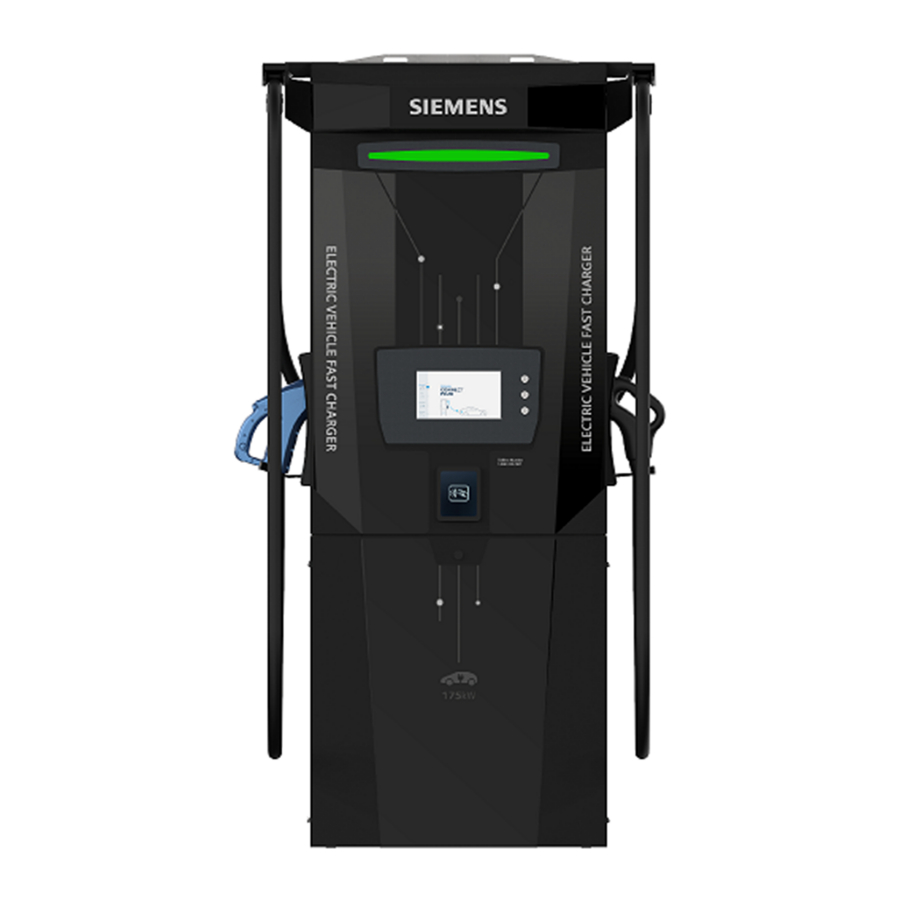
- Page 1 Front Back Installation Manual VersiCharge Ultra 175 ™ 175 kW DC fast charger usa.siemens.com/versicharge...
-
Page 2: Table Of Contents
Table of Contents Important safety instructions. Save these instructions FCC Notice Packaging, handling and receipt Site configuration Baseplate dimensions Installation requirements and equipment Unpacking Installation Wire and commissioning Ethernet port access Fiber optic access Closing checklist VersiCharge Ultra 175 System Installation Checklist... -
Page 3: Important Safety Instructions. Save These Instructions
ø CAUTION Phase Symbol ∿ The VersiCharge Ultra 175 kW DC charger unit must be installed and serviced only by qualified electrical personnel. Alternating Current Supply Symbol To achieve EMC compliance, the chassis of the VersiCharge Ultra 175 fast charger unit must be bonded to Earth locally at the charger. - Page 4 Adaptors shall not be used to connect a vehicle connector to 50/60 Hz a vehicle inlet. The VersiCharge Ultra 175 unit must be connected to a circuit provided with appropriate over-current protection in accor- dance with the National Electrical Code, ANSI/NFPA 70.
-
Page 5: Fcc Notice
(FCC Part 15.105) (FCC Part 15.21) Class A product: Warning: Any changes or modifications not expressively approved by (Siemens) could void the user’s authority to NOTE: operate this equipment This equipment has been tested and found to comply with the limits for a Class A digital device, pursuant to part 15 of the FCC rules. -
Page 6: Packaging, Handling And Receipt
VersiCharge Ultra 175 unit is not damaged. In all cases, the VersiCharge Ultra 175 unit must be transported If there are any problems noted, make a formal complaint to the to the installation site in its original packaging, and only carrier and notify your supplier. -
Page 7: Site Configuration
Ground fixing: UU. If the UU and IPU are configured for use of optical fiber, The VersiCharge Ultra 175 unit is fixed to the ground through the then use optical fiber. If not, use Ethernet (default). baseplate fixing holes with 4 x M16 fasteners or 5/8 inch 4G network capability. - Page 8 VersiCharge Ultra 175™ | Installation Manual Site configuration Servicing distance An additional space of 700mm from the center front and rear of the VerisCharge Ultra 175 unit is required to open the front panel for servicing, as shown in Figure 1.
-
Page 9: Baseplate Dimensions
Installation Manual | VersiCharge Ultra 175™ Baseplate dimensions Note: Do not scale. All dimensions shown in mm. A mounting stencil may be supplied by Siemens at the customer’s request. -
Page 10: Installation Requirements And Equipment
These instructions provide a systematic guide for installing and commissioning the VersiCharge Ultra 175 unit. • Socket set and ratchet The VersiCharge Ultra 175 unit must be installed and serviced by • Torque wrench with 30Nm setting qualified electrical personnel. -
Page 11: Unpacking
Ultra 175 to the lifting apparatus, and gently raise to a upright apparatus. position on the shipping baseplate. Remove/slide out all crate tubes to disassemble the cardboard NOTE: The VersiCharge Ultra 175 unit is 2060mm tall on the crate. shipping baseplate. Once upright, remove all wrapping. Ensure the connection to the lifting apparatus is secure at all times. -
Page 12: Installation
4. Secure to foundation Follow this step to increase visibility and access to the mounting Lift the VersiCharge Ultra 175 unit and place over the prepared holes. If visibility and access is sufficient, go to step 3. Use the foundation. Feed the conduit and wiring through the power 4mm Allen wrench to unscrew the 4 screws that attach the rear in-hole, and secure to the foundation fixing points. - Page 13 5. Remove enclosure access cover CAUTION Remove the enclosure access cover screws with the 4mm Allen wrench to prepare the VersiCharge Ultra 175 for wiring To continue to achieve the NEMA 3R rating the power installation. cabling must be fitted correctly into the cable gland.
-
Page 14: Wire And Commissioning
30 Nm / 22 lb-ft qualified electrical personnel only. The wiring diagram is also available on the inside of the Note: Refer to Siemens VersiCharge Ultra 175 Site Installation Service Hatch. Manual for a table of all torques used during installation. - Page 15 Installation Manual | VersiCharge Ultra 175™ Wire and commissioning Note: For all field wiring terminal connections, refer to the CRITICAL wiring diagram sticker on the reverse of the access hatch cover. If the single-phase wiring is run in a three-core cable (2C+E), 2.
-
Page 16: Ethernet Port Access
VersiCharge Ultra 175™ | Installation Manual Ethernet port access The Ethernet port is situated on the front of the enclosure box. Twist to disengage the base cap and wire in the Cat 6a STP Ethernet cable. Ensure the base cap is securely fitted back into the holder for IP65 protection. -
Page 17: Fiber Optic Access
Installation Manual | VersiCharge Ultra 175™ Fiber optic access If fiber is to be utilized, then a fiber optic interface module is required. If this is the case, the fiber optic module shall be mounted at the bottom of the unit. -
Page 18: Closing Checklist
VersiCharge Ultra 175™ | Installation Manual Closing checklist Follow these steps in order to ready the unit for commissioning: 3. Attach the rear lower panel Lift the panel, slide it over the fixing points and rubber cable flanges on both sides until it is secure under the top panel, and 1. - Page 19 Closing checklist 4. Plug in the parking sensor 5. Attach the front-lower panel The VersiCharge Ultra 175 unit has a parking sensor available for Raise and slide the front-lower panel into the fixing points use on the front, lower panel.
-
Page 20: Versicharge Ultra 175 System Installation Checklist
Installation Manual | VersiCharge Ultra 175™ Notes:... - Page 21 Actual results are dependent on variable conditions. Accordingly, Siemens does not make representations, warranties, or assurances as to the accuracy, currency or completeness of the content contained herein. If requested, we will provide specific technical data or specifications with respect to any customer’s particular applications.