Table of Contents
Advertisement
Quick Links
19
Initial setup guide
Last updated: 9th of Nov 2018
This guide contains extracts from the user manual for the VB50 COFDM Probe. Its intention is to
give the necessary information to install and configure the IP address of the unit in condensed form.
For further information on how to operate the equipment please refer to the user manual directly. It
can be downloaded by accessing the URL: https://bridgetech.tv/vb50-vb60/
Safety points
Read the installation instructions before connecting the chassis unit to the power source.
The VB50 is intended for installation in restricted access areas. A restricted access area can be
accessed only through the use of a special tool, lock and key, or other means of security.
The VB50 must only be used with the included power supply. Do not use the power supply if it
or its cables are damaged.
Only trained and qualified personnel should be allowed to install, replace or service this
equipment.
This equipment must be installed and maintained by service personnel as defined by AS/NZS
3260. Incorrectly connecting this equipment to a general-purpose outlet could be hazardous.
Ultimate disposal of this product should be handled according to all national laws and
regulations.
To prevent the system from overheating, do not operate it in an area that exceeds the
maximum ambient temperature of 45 degrees Celsius. Do not place other objects on top of the
VB50 or closer than 2 inches to the sides and top of the unit as this may cause heat to build up
which could damage the unit. Air needs to flow freely around the sides and top of the unit.
Do not work on the system or connect or disconnect cables during periods of lightning
activity.
The VB50 requires short-circuit (over-current) protection. Ensure that the protective device is
rated not greater than 120 VAC, 15 A; 240 VAC, 16 A.
If SFP modules are used ensure proper precautions are taken to protect eyes against harmful
infrared radiation. Do not look straight into the SFP module or fibers connected to the SFP
module. The SFP modules employed are certified in Laser Class 1.
In particularly dusty environments and if the wall-mount bracket is being used it may be an
advantage to mount the unit in such a way that the connectors face downwards in order to
avoid dust settling onto the RJ45 and SFP connectors.
1-9
Advertisement
Table of Contents

Related Manuals for Bridge Technologies VB50 COFDM


Summary of Contents for Bridge Technologies VB50 COFDM
- Page 1 Last updated: 9th of Nov 2018 This guide contains extracts from the user manual for the VB50 COFDM Probe. Its intention is to give the necessary information to install and configure the IP address of the unit in condensed form.
-
Page 2: Ac Power Supply
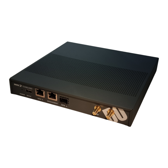
29 The VB50 COFDM Probe The VB50 COFDM Probe is built for real world use. Its steel exterior and fan-less design makes it suitable for permanent placement in a harsh environment. The dedicated and custom design enables high uptime, stability and longevity. -
Page 3: Cooling System
The serial number is located at the back of the unit in the vicinity of where the +12V power inlet is. All serial numbers can also be found on the shipping box. The serial number of the VB50 COFDM Probe is also available via the web GUI under About — License. -
Page 4: Connecting Signal Cables
49 RF: RF input – 50 ohm SMA female connector for monitoring RF signals as found in digital terrestrial networks (COFDM). Supported standards are DVB-T/DVB-T2 and ISDB-T/Tb. 1PPS 1PPS GPS input timing reference - 50 ohm SMA female connector. SERIAL: Serial SETUP port for initial set-up of the Probe using serial protocol emulated over USB. - Page 5 59 Initial set-up of IP address There are two alternative ways of performing an initial configuration of the Probe unit: 1. By using the pre-configured IP address of the Probe management port 2. SETUP via serial console emulated over USB For most users the first method will be the easiest.
- Page 6 69 following: 1. Installing a driver for the USB communication, if not already supported by the operating system 2. Setting the management IP address Most operating systems will have native support for the FT232 driver needed. When a USB cable is connected between a PC and the Probe, the operating system will detect a new USB device.
- Page 7 79 Stop bits: 1 Flow control: None Press Enter a few times to bring up the login prompt. Log in using the user name admin and the password elvis (this password can be changed in the Setup – Security view). A simple text based menu system like the one in figure below should now be displayed.
- Page 8 89 Verify that GUI launches correctly Once the Probe management network interface have been configured, all further configuration takes place using a web browser over HTTP/HTTPS. Launch a web browser application on the management PC. The following web browsers are supported: Microsoft Edge Microsoft Internet Explorer 11 or higher...
-
Page 9: Initial Troubleshooting
Other Sources of Information Following are some additional resources to consider if you need information that is not part of the BRIDGE Technologies technical documentation, or if you have questions that are not related to a particular product. General information To learn more about BRIDGE Technologies products, services, and company news.