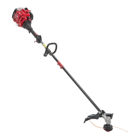
Troy-Bilt TB 35 EC Addendum
Hide thumbs
Also See for TB 35 EC:
- Operator's manual (40 pages) ,
- Operator's manual (40 pages) ,
- Operator's manual (20 pages)
Advertisement
Available languages
Available languages
Quick Links
NOTE: The product may vary slightly from the illustrations contained in these instructions.
WARNING:
Carefully read and understand the operator's
manual of the unit that powers this accessory. Follow all
safety instructions contained therein. Failure to do so can
result in serious injury to the operator and/or bystanders.
WARNING:
To prevent serious injury, never replace the
cutting head while the unit is running. Always allow the unit
to cool before replacing the cutting head. Disconnect the
spark plug wire to prevent the unit from starting
accidentally. Refer to the trimmer operator's manual for
stopping instructions and spark plug information.
WARNING:
To prevent serious injury, wear protective
gloves when swapping cutting heads. Avoid contact with
the line cutting blade on the cutting head shield.
Tools Required:
•
1/2 inch (13 mm) wrench
REMOVING THE BUMP HEAD CUTTING HEAD AND
INSTALLING THE AERO-FLEX
Removing the Bump Head Cutting Head
1. Hold the cutting head in place. Turn the bump knob clockwise to
unscrew it from the cutting head (Fig. 1).
2. Slide the cutting head off of the arbor (Fig. 1).
Installing the Aero-Flex Cutting Head
1. Slide the cutting head base onto the arbor (Fig. 2). Make sure
that the cutting head base fits securely onto the hexagonal
portion of the arbor.
2. Insert the bolt into the center of the cutting head base (Fig. 3).
Turn the bolt counterclockwise with a 1/2 inch (13 mm) wrench
to tighten the bolt securely.
3. Hold one of the line blades so that the loop faces to the right.
Align the loop with one of the posts on the cutting head base
(Fig. 4). Push the loop onto the post securely.
4. Repeat step 3 until all four line blades are installed (two yellow
and two orange). Always alternate between yellow and orange
line blades (Fig. 5). Do not install two line blades of the same
color next to each other.
5. Align the tabs on the cutting head cap with the tab slots on the
cutting head base (Fig. 6). Push the cutting head cap onto the
cutting head base until both tabs snap into place.
WARNING:
Never install less than four line blades. Doing
so could make the unit unstable and hard to control, which
could result in serious personal injury.
769-11738 / 00
ADDENDUM
®
CUTTING HEAD
Fig. 1
Fig. 2
Fig. 3
Line Blade
Loop
Line Blade Slot
Post
Fig. 4
Arbor
Bump Knob
Cutting Head
Cutting Head Base
Arbor
Bolt
Cutting Head
Base
Cutting Head
Base
06/16
Advertisement

Related Manuals for Troy-Bilt TB 35 EC


Summary of Contents for Troy-Bilt TB 35 EC
- Page 1 ADDENDUM NOTE: The product may vary slightly from the illustrations contained in these instructions. WARNING: Carefully read and understand the operator's Arbor manual of the unit that powers this accessory. Follow all safety instructions contained therein. Failure to do so can Bump Knob result in serious injury to the operator and/or bystanders.
- Page 2 REMOVING THE AERO-FLEX ® CUTTING HEAD AND Yellow Line Blade INSTALLING THE BUMP HEAD CUTTING HEAD Removing the Aero-Flex Cutting Head Orange Line Blade 1. Firmly press both tabs inward and pull the cutting head cap away from the cutting head base (Fig. 6). If necessary, use a flat- head screwdriver to lever the tabs.
- Page 3 ANEXO NOTA: El producto puede variar levemente de las ilustraciones contenidas en estas instrucciones. ADVERTENCIA: Lea con atención y familiarícese con el Mandril manual del operador de la unidad que suministra potencia a este accesorio. Tenga en cuenta todas las instrucciones de Perilla de impacto seguridad que incluye.
- Page 4 RETIRO DEL CABEZAL DE CORTE AERO-FLEX ® Cuchilla recta amarilla INSTALACIÓN DEL CABEZAL DE CORTE DEL CABEZAL DE IMPACTO Cuchilla recta Retirar el cabezal de corte Aero-Flex anaranjada 1. Presione firmemente las dos lengüetas hacia adentro y tire del cabezal de corte para separarlo de la base del cabezal de corte (Fig.