HP 3478A Technical Manual
Hide thumbs
Also See for 3478A:
- Service manual (160 pages) ,
- Technical manual (150 pages) ,
- Operating instructions manual (103 pages)
Advertisement
Quick Links
TECHNICAL MANUAL
TECHNICAL MANUAL
OPERATOR'S ORGANIZATIONAL, DIRECT SUPPORT,
OPERATOR'S ORGANIZATIONAL, DIRECT SUPPORT,
AND GENERAL SUPPORT MAINTENANCE MANUAL
AND GENERAL SUPPORT MAINTENANCE MANUAL
DILGITAL MULTIMETER
DILGITAL MULTIMETER
HEWLETT - PACKARD MODEL 3478A
HEWLETT - PACKARD MODEL 3478A
HEADQUARTERS, DEPARTMENT OF THE ARMY
HEADQUARTERS, DEPARTMENT OF THE ARMY
TM 11-6625-3071-14
TM 11-6625-3071-14
5 MARCH 1985
5 MARCH 1985
Advertisement

Related Manuals for HP 3478A


Summary of Contents for HP 3478A
- Page 1 OPERATOR’S ORGANIZATIONAL, DIRECT SUPPORT, AND GENERAL SUPPORT MAINTENANCE MANUAL AND GENERAL SUPPORT MAINTENANCE MANUAL DILGITAL MULTIMETER DILGITAL MULTIMETER HEWLETT - PACKARD MODEL 3478A HEWLETT - PACKARD MODEL 3478A HEADQUARTERS, DEPARTMENT OF THE ARMY HEADQUARTERS, DEPARTMENT OF THE ARMY 5 MARCH 1985...
- Page 2 TM 11-6625-3071-14 TM 11-6625-3071-14...
- Page 3 TM 11-6625-3071-14 TM 11-6625-3071-14 hp-HEWLETT hp-HEWLETT PACKARD PACKARD SAFETY SUMMARY SAFETY SUMMARY The following general safety precautions must be observed during all phases of operation, service, and repair of The following general safety precautions must be observed during all phases of operation, service, and repair of...
- Page 4 TM 11-6625-3071-14 TM 11-6625-3071-14 C/ (D BLANK) C/ (D BLANK)
- Page 5 OPERATOR’S, ORGANIZATIONAL DIRECT SUPPORT, AND GENERAL SUPPORT DIRECT SUPPORT, AND GENERAL SUPPORT MAINTENANCE MANUAL MAINTENANCE MANUAL DIGITAL MULTIMETER HP MODEL 3478A DIGITAL MULTIMETER HP MODEL 3478A Serial Numbers: 2136A00101 and Greater Serial Numbers: 2136A00101 and Greater IMPORTANT NOTICE IMPORTANT NOTICE...
- Page 6 TM 11-6625-3071-14 TM 11-6625-3071-14 TABLE OF CONTENTS TABLE OF CONTENTS Section Section Page Page 0. 0. INTRODUCTION INTRODUCTION 0-1. 0-1. Scope Scope ........................................................0-1 ..0-1 0-2. 0-2. Consolidated Consolidated Index Index of of Army Army Publications Publications and and Blank...
- Page 7 Performance Test Test and 3-70. 3-70. General......... General..........3-8 3-74. 3-74. 3478A 3478A Response Response to to Bus Bus Message Messages. s. 3 3 - - 8 8 Calibration Calibration 1-11. 1-11. Section Section V, V, Replaceable Replaceable Parts..
- Page 8 ...... . 5-3 4-2. 4-2. Recommended Test Equipment Recommended Test Equipment ........4-2 ..4-2 5-4. 5-4. 3478A Mechanical and 3478A Mechanical and 4-3. 4-3. DC Volts DC Volts Test Limits Test Limits ............
- Page 9 ....7-D-10 ...7-D-10 2-5. 2-5. HP-IB HP-IB Connecto Connector r ............2-4 7-F-1. 7-F-1. 3478A 3478A Simplified Simplified Block Block 2-6. 2-6. 3478A 3478A Address Address Switch Switch ......... . 2-4 Diagram ........
- Page 10 S S C C O O P P E E This manual describes the This manual describes the Digital Multimeter, HP Model 3478A and Digital Multimeter, HP Model 3478A and provides instructions for operation and maintenance. provides instructions for operation and maintenance. 0- 0-2. 2.
- Page 11 3478A unless you are qualified to do servicing to the 3478A unless you are qualified to do so. Theory Of Operation, and Schematics are in Section VII. Theory Of Operation, and Schematics are in Section VII.
- Page 12 TM 11-6625-3071-14 TM 11-6625-3071-14 Table 1-1. Specification Table 1-1. Specification ...
- Page 13 TM 11-6625-3071-14 TM 11-6625-3071-14 Table 1-1. Specifications. Cont. Table 1-1. Specifications. Cont.
- Page 14 TM 11-6625-3071-14 TM 11-6625-3071-14 Table 1-1. Specifications. Cont. Table 1-1. Specifications. Cont.
- Page 15 (suffix) identifying a particular instrument and one extension adapter (-hp- Part and one extension adapter (-hp- Part No. 5061-0072) No. 5061-0072) within a series. An -hp- assigned alpha character l within a series. An -hp- assigned alpha character l Option Option 910:...
- Page 16 3478A unless you are qualified to do servicing to the 3478A unless you are qualified to do so. (below the power receptacle). If the (below the power receptacle). If the ...
- Page 17 3478A’s power transformer (see 3478A’s power transformer (see Figure 2-2) Figure 2-2). . 3478A. The -hp- part number shown directly below the 3478A. The -hp- part number shown directly below the individual power plug drawing, is the part number for the individual power plug drawing, is the part number for the c.
- Page 18 Refer to the Remote Operation Chapter in Sec- tion III of kit is designed to permit the 3478A to be kit is designed to permit the 3478A to be mounted in a mounted in a this manual, for more information on ad- dressing and...
- Page 19 If you by model number and full serial number. If you have any questions, contact your nearest -hp- have any questions, contact your nearest -hp- d. d. Mar Mark shipp k shipping co...
- Page 20 Oper erat atio ion - n - paragraph 3-17. paragraph 3-17. completed and the 3478A passes the test, the 3478A’s completed and the 3478A passes the test, the 3478A’s T T i i t t l l e e P P a a r r a a g g r r a a p p h h...
- Page 21 This is the Amps input terminal and is used w erminal and is used with the ith the resets the 3478A to its turn-on state. Any errors in the resets the 3478A to its turn-on state. Any errors in the INPUT LOW terminal. 13 Amp INPUT LOW terminal.
- Page 22 Function, ranging is done anging is done in the Input Circuitry of the 3478A. The result is that the in the Input Circuitry of the 3478A. The result is that the input to the A/D Converter (which changes the...
- Page 23 3478A’s A/D Converter. All ranging is done in the AC to 3478A’s A/D Converter. All ranging is done in the AC to...
- Page 24 The mode is selected due to self-heating. This may cause due to self-heating. This may cause when the 3478A is first turned on or by pressing the when the 3478A is first turned on or by pressing the inaccuracies inaccuracies measurement.
- Page 25 3 3 - - 5 5 1 1 . . G G e e n n e e r r a a l l 3-52. The Shifted Operation of the 3478A is used to 3-52. The Shifted Operation of the 3478A is used to...
- Page 26 Since no more offset readings are taken, the reading Since no more offset readings are taken, the reading rate of the 3478A is faster (up to twice as fast). If a rate of the 3478A is faster (up to twice as fast). If a 3 3 - - 6 6 3 3 .
- Page 27 34 e 3478A 78A’s ’s 3478A related HP-IB information. It is assumed, in the 3478A related HP-IB information. It is assumed, in the response to Bus Messages. The multimeter’s Bus response to Bus Messages. The multimeter’s Bus...
- Page 28 Message is cleared. multimeter’s output (readings) and status information. In multimeter’s output (readings) and status information. In this case, the 3478A is the Talker and the controller is this case, the 3478A is the Talker and the controller is 3-83.
- Page 29 See paragraph 3-115. e paragraph 3-115. the 3478A is set by the Address Switch on its rear panel. the 3478A is set by the Address Switch on its rear panel. Setting the 3478A’s Listen Address also sets its Talk Address.
- Page 30 Programming the the SRQ Mask. SRQ Mask. The SRQ Mask The SRQ Mask must be set for the 3478A to output a Require Service must be set for the 3478A to output a Require Service Message. Message. Setting the S...
- Page 31 C C l l e e a a r r s s S S t t a a t t u u s s R R e e g g i i s s t t e e r r (when sent to the 3478A over the HP-IB) are used to set...
- Page 32 (DCV). This command is the same This command is the same the 3478A is in the 4 1/2 or 3 1/2 Digit mode, the 5th the 3478A is in the 4 1/2 or 3 1/2 Digit mode, the 5th as the "HO” command, except a trigger occurs and the as the "HO”...
- Page 33 0V AC AC, 30 , 30K O K Ohm hm Ra Rang nges is only available over the HP-IB and is used to measure is only available over the HP-IB and is used to measure XXX1 X101 01XX 300V 0V DC...
- Page 34 (% of reading + number of (% of reading + number of counts) counts) it in the environment in which the 3478A is to be calibrated it in the environment in which the 3478A is to be calibrated Range Range...
- Page 35 If the 3478A is to be tested and calibrated at full scale, If the 3478A is to be tested and calibrated at full scale, substitute calibrator that meets the requirements listed substitute calibrator that meets the requirements listed...
- Page 36 + .0005° 5° o or better. o or better. of this section and are to be used to record the 3478A's of this section and are to be used to record the 3478A's performance. performance. It is recommended t...
- Page 37 (.005%o), but the number of counts is different and different and standard is within its limits, it may show the 3478A to be standard is within its limits, it may show the 3478A to be in or out of in or out of its limits.
- Page 38 1 hour warm-up time. Digital Voltmeter (-hp- Model 3456A) Digital Voltmeter (-hp- Model 3456A) If the 3478A has been on for less time, inaccuracies can If the 3478A has been on for less time, inaccuracies can DC Volts Standard (Systron Donner Model...
- Page 39 3478A’s INPUT Terminals and set the multimeter to the 3478A’s INPUT Terminals and set the multimeter to the 30mV Range. 30mV Range. i. i. (Step #9.) Se (Step #9.) Set the 3478A t...
- Page 40 Make sure the DC Volts Make sure the DC Volts the standard to the 3478A as shown in the standard to the 3478A as shown in Figure 4-3. Figure 4-3. Performance Test has been completed, before doing the Performance Test has been completed, before doing the DC Current DC Current Test.
- Page 41 .03V at 20KHz and .3V at 20KHz, Voltmeter from the AC-DC Current Calibrator Remove Voltmeter from the AC-DC Current Calibrator Remove the current calibrator from the 3478A. completes the DC the current calibrator from the 3478A. completes the DC Table 4-5.
- Page 42 Record the readings. readings. troubleshooting. troubleshooting. e. e. (Step #5, 6, (Step #5, 6, and 7.) Set the and 7.) Set the 3478A to the 3V Range. 3478A to the 3V Range. 4-64. 4-64. AC AC Current Current Test Test...
- Page 43 3478A in connections or test leads used to calibrate the 3478A in the 2-Wire Ohms Function must also be used when the 2-Wire Ohms Function must also be used when...
- Page 44 Ω Ω Ω Ω Ω Ω 3478A’s display and record the reading on the Test Card. 3478A’s display and record the reading on the Test Card. connecting the following standard resistors to the connecting the following standard resistors to the multimeter’s input: 300...
- Page 45 Downrange button until the displayed reading Downrange button until the displayed reading Since it is a zero input, the 3478A should now display + Since it is a zero input, the 3478A should now display + agrees...
- Page 46 ± 1000 counts (e.g. reads a value of greater than ± 1000 counts (e.g. the calibration and test signals are applied to the 3478A's the calibration and test signals are applied to the 3478A's reads I ohm on the 30 ohm range).
- Page 47 (CAL) button. (CAL) button. check and make sure the 3478A reading is within the check and make sure the 3478A reading is within the specified limits shown in specified limits shown in Table 4-8. Table 4-8.
- Page 48 30V Range 30V Range the standard to the 3478A as shown in the standard to the 3478A as shown in Figure 4-3. Figure 4-3. are to be made, do the following: are to be made, do the following: 5.
- Page 49 Shift button and ton and then the then the LOCAL LOCAL calibrate the 3478A by doing the procedure in steps f and calibrate the 3478A by doing the procedure in steps f and (CAL) button. (CAL) button. g. g.
- Page 50 (per Table 4-10) Table 4-10). . r. r. (Step #18 and 19.) Set (Step #18 and 19.) Set the 3478A to the 30V Range. the 3478A to the 30V Range. Check the 1/2 and full scale accuracy of the range by Check the 1/2 and full scale accuracy of the range by k.
- Page 51 SGL/TRIG and then the SGL/TRIG (TEST/RESET) button. (TEST/RESET) button. 3478A is to be calibrated in the 2-Wire Ohms Function, 3478A is to be calibrated in the 2-Wire Ohms Function, connect the Standard Resistors to the 3478A’s HI and connect the Standard Resistors to the 3478A’s HI and...
- Page 52 SGL/TRIG and then the SGL/TRIG (TEST/RESET) button. (TEST/RESET) button. o. o. (Step #11 and 12.) Set (Step #11 and 12.) Set the 3478A to the 3M the 3478A to the 3M( Range ( Range b. b. Make sure t...
- Page 53 TM 11-6625-3071-14 TM 11-6625-3071-14...
- Page 54 TM 11-6625-3071-14 TM 11-6625-3071-14...
- Page 55 TM 11-6625-3071-14 TM 11-6625-3071-14...
- Page 56 TM 11-6625-3071-14 TM 11-6625-3071-14...
- Page 57 TM 11-6625-3071-14 TM 11-6625-3071-14 PERFORMANCE TEST CARD PERFORMANCE TEST CARD 1 YEAR LIMITS 1 YEAR LIMITS H H e e w w l l e e t t t t - - P P a a c c k k a a r r d d M M o o d d e e l l 3 3 4 4 7 7 8 8 A A T T e e s s t t P P e e r r f f o o r r m m e e d d B B y y _ _ _ _ _ _ _ _ _ _ _ _ _ _ _ _ _ _ _ _ _ _ _ _ _ _ _ _ _ _ _ _ _ _ _ _ _ _ _ _ _ _ _ ...
- Page 58 TM 11-6625-3071-14 TM 11-6625-3071-14 PERFORMANCE TEST CARD PERFORMANCE TEST CARD 1 YEAR LIMITS 1 YEAR LIMITS H H e e w w l l e e t t t t - - P P a a c c k k a a r r d d M M o o d d e e l l 3 3 4 4 7 7 8 8 A A T T e e s s t t P P e e r r f f o o r r m m e e d d B B y y _ _ _ _ _ _ _ _ _ _ _ _ _ _ _ _ _ _ _ _ _ _ _ _ _ _ _ _ _ _ _ _ _ _ _ _ _ _ _ _ _ _ _ ...
- Page 59 TM 11-6625-3071-14 TM 11-6625-3071-14 PERFORMANCE TEST CARD PERFORMANCE TEST CARD 1 YEAR LIMITS 1 YEAR LIMITS H H e e w w l l e e t t t t - - P P a a c c k k a a r r d d M M o o d d e e l l 3 3 4 4 7 7 8 8 A A T T e e s s t t P P e e r r f f o o r r m m e e d d B B y y _ _ _ _ _ _ _ _ _ _ _ _ _ _ _ _ _ _ _ _ _ _ _ _ _ _ _ _ _ _ _ _ _ _ _ _ _ _ _ _ _ _ _ ...
- Page 60 TM 11-6625-3071-14 TM 11-6625-3071-14 PERFORMANCE TEST CARD PERFORMANCE TEST CARD 1 YEAR LIMITS 1 YEAR LIMITS H H e e w w l l e e t t t t - - P P a a c c k k a a r r d d M M o o d d e e l l 3 3 4 4 7 7 8 8 A A T T e e s s t t P P e e r r f f o o r r m m e e d d B B y y _ _ _ _ _ _ _ _ _ _ _ _ _ _ _ _ _ _ _ _ _ _ _ _ _ _ _ _ _ _ _ _ _ _ _ _ _ _ _ _ _ _ _ ...
- Page 61 TM 11-6625-3071-14 TM 11-6625-3071-14 PERFORMANCE TEST CARD PERFORMANCE TEST CARD 1 YEAR LIMITS 1 YEAR LIMITS H H e e w w l l e e t t t t - - P P a a c c k k a a r r d d M M o o d d e e l l 3 3 4 4 7 7 8 8 A A T T e e s s t t P P e e r r f f o o r r m m e e d d B B y y _ _ _ _ _ _ _ _ _ _ _ _ _ _ _ _ _ _ _ _ _ _ _ _ _ _ _ _ _ _ _ _ _ _ _ _ _ _ _ _ _ _ _ ...
- Page 62 NON-LISTED PARTS alphameric order of their reference designators and alphameric order of their reference designators and indicates the description, -hp- Part Number of each part, indicates the description, -hp- Part Number of each part, 5-7. 5-7. To obtain a part t...
- Page 63 Remove Remove the the top cover by pulling the cover toward the rear of the 3478A cover by pulling the cover toward the rear of the 3478A m. Remove the Remove the front frame (M...
- Page 64 Replaceable Parts Replaceable Parts TM 11-6625-3071-14 TM 11-6625-3071-14 Table 5 Table 5-3. -3. Replaceable Replaceable Parts Parts R R e e f f e e r r e e n n c c e e H H P P P P a a r r t t C C Q Q t t y y D D e e s s c c r r i i p p t t i i o o n n M M f f r r...
- Page 65 Replaceable Parts Replaceable Parts TM 11-6625-3071-14 TM 11-6625-3071-14 Table 5 Table 5-3. -3. Replaceable Replaceable Parts Parts R R e e f f e e r r e e n n c c e e H H P P P P a a r r t t C C Q Q t t y y D D e e s s c c r r i i p p t t i i o o n n M M f f r r...
- Page 66 Replaceable Parts Replaceable Parts TM 11-6625-3071-14 TM 11-6625-3071-14 Table 5 Table 5-3. -3. Replaceable Replaceable Parts Parts R R e e f f e e r r e e n n c c e e H H P P P P a a r r t t Q Q t t y y D D e e s s c c r r i i p p t t i i o o n n M M f f r r...
- Page 67 Replaceable Parts Replaceable Parts TM 11-6625-3071-14 TM 11-6625-3071-14 Table 5 Table 5-3. -3. Replaceable Replaceable Parts Parts R R e e f f e e r r e e n n c c e e H H P P P P a a r r t t C C Q Q t t y y D D e e s s c c r r i i p p t t i i o o n n M M f f r r...
- Page 68 Replaceable Parts Replaceable Parts TM 11-6625-3071-14 TM 11-6625-3071-14 Table 5 Table 5-3. -3. Replaceable Replaceable Parts Parts R R e e f f e e r r e e n n c c e e H H P P P P a a r r t t Q Q t t y y D D e e s s c c r r i i p p t t i i o o n n M M f f r r...
- Page 69 TM 11-6625-3071-14 TM 11-6625-3071-14 Table 5-4. Table 5-4. 3478A Mechanical a 3478A Mechanical and Miscellaneous Par nd Miscellaneous Parts ts R R e e f f . . P P a a r r t t D D e e s s . .
- Page 70 TM 11-6625-3071-14 TM 11-6625-3071-14 SECTION VI SECTION VI BACKDATING BACKDATING 6-1. INTRODUCTION 6-1. INTRODUCTION 6-2. 6-2. This section This section has has information information which which adapts adapts this this manual to instruments with serial numbers below the manual to instruments with serial numbers below the ones shown on ones shown on the title the title page.
- Page 71 This section of the manual has infor e manual has information on how mation on how to troubleshoot and repair the 3478A multimeter with the to troubleshoot and repair the 3478A multimeter with the Any interruptions of the protective grounding ...
- Page 72 Main Power Fuse. Main Power Fuse. To replace To replace the main the main power power indicates that the 3478A has failed its internal ROM self indicates that the 3478A has failed its internal ROM self fuse, fuse, first first remove...
- Page 73 Once the failure Once the failure has been det has been determined, go t ermined, go to the o the the 3478A displays a certain reading (with no input the 3478A displays a certain reading (with no input recommended recommended group. group.
- Page 74 Inoperative Keyboard. Inoperative Keyboard. An Inoperative Inoperative Keyboard is when part or all of the 3478A’s keyboard is Keyboard is when part or all of the 3478A’s keyboard is b. b. A/D Slope Error. A/D Slope Error. This failure ca...
- Page 75 + + 1 1 4 4 . . 4 4 V V t t o o + + 1 1 5 5 . . 6 6 V V determines the general area of the 3478A that causes determines the general area of the 3478A that causes...
- Page 76 3478A is calibrated using zero and positive full scale (or 3478A is calibrated using zero and positive full scale (or DC/Ohms Input DC/Ohms Input Amplifier.
- Page 77 Constant Zero Readings on Readings on All Ranges All Ranges f. f. If the display If the displayed reading on the 347 ed reading on the 3478A is + 3V, the 8A is + 3V, the 7-A-26. 7-A-26. A const...
- Page 78 Turn the 3478A off 3478A off. . c. c. If the reading If the reading on the 3478A on the 3478A is quiet with Autoze is quiet with Autozero ro b. b. Move jumpers JM502 Move jumpers JM502, JM503, an...
- Page 79 AC to DC AC to DC Converter, Converter, make sure the 3478A’s DC Volts and DC Current make sure the 3478A’s DC Volts and DC Current make sure relay K104 (see Schematic 1) is good and is make sure relay K104 (see Schematic 1) is good and is...
- Page 80 AC to DC Conver DC Converter is ter is d. d. Turn the 3478A on Turn the 3478A on and check for the and check for the following following calibrated with an input voltage at a frequency of 1KHz, calibrated with an input voltage at a frequency of 1KHz, signatures.
- Page 81 3478A and is symptoms shooting information for the 3478A and is symptoms troubleshooting procedures (go to troubleshooting procedures (go to paragraph 7-32 paragraph 7-32 for a for a oriented oriented (i.e.,...
- Page 82 3478A’s HI INPUT Terminal. 3478A’s HI INPUT Terminal. across the resistor is developed and the 3478A across the resistor is developed and the 3478A measures measures zero...
- Page 83 Function only, U102 may , U102 may be defective. be defective. Before replacing Before replacing apply -10V dc to the 3478A’s INPUT Terminals. apply -10V dc to the 3478A’s INPUT Terminals. U102, make sure U102, make sure the A/D Co the A/D Controller (U462) is ntroller (U462) is good.
- Page 84 Refer to Schematic 3. U201. U201. a. a. Turn the Turn the 3478A off 3478A off. . 7. 7. If the volta If the voltage at pin 6 of U201 is + ge at pin 6 of U201 is +8V, replace 8V, replace U102.
- Page 85 This Service Group has the has the A/D Convert A/D Converter and er and Logic Circuitry troubleshooting information for the 3478A. Logic Circuitry troubleshooting information for the 3478A. The instrument contains CMOS Integrated Circuits The instrument contains CMOS Integrated Circuits ...
- Page 86 U5O1 pin 27: P6H5 U5O1 pin 27: P6H5 Data Lines may be good, but the 3478A may be in- Data Lines may be good, but the 3478A may be in- U501 pin 28: PF57 U501 pin 28: PF57 operative.
- Page 87 TM 11-6625-3071-14 TM 11-6625-3071-14 3478A 3478A Figure Figure 7-D-3. 7-D-3. Flowchart Flowchart B B 7-D-5 7-D-5...
- Page 88 TM 11-6625-3071-14 TM 11-6625-3071-14 3478A 3478A Figure Figure 7-D-4. 7-D-4. Flowchart Flowchart C C 7-D-6 7-D-6...
- Page 89 RAM, the data in he data in the RAM will be lost and the 3478A will need to be the RAM will be lost and the 3478A will need to be 2.If pin 4 of U514 is low, replace U514.
- Page 90 Error. . When an When an "A:D SLOPE "A:D SLOPE ERR" ERR" is displayed on the 3478A, the most likely cause is the is displayed on the 3478A, the most likely cause is the b. b. If t If the RE...
- Page 91 TM 11-6625-3071-14 TM 11-6625-3071-14 3478A 3478A Figure Figure 7-D-6. 7-D-6. Flowchart Flowchart D D 7-D-9 7-D-9...
- Page 92 "HF52" a 52" and t nd the line, press the 3478A’s blue Shift button and then the line, press the 3478A’s blue Shift button and then the SA probe is toggling, the Main Controller (U501) may be SA probe is toggling, the Main Controller (U501) may be SGL/TRIB (TEST/RESET) bu SGL/TRIB (TEST/RESET) button.
- Page 93 JM702 for the -15V supply he -15V supply. . If the sup- If the sup- troubleshoot the 3478A’s Power Supplies and Reference troubleshoot the 3478A’s Power Supplies and Reference ply is now good, troubleshoot the Floating Common ply is now good, troubleshoot the Floating Common Circuitry.
- Page 94 TM 11-6625-3071-14 TM 11-6625-3071-14 3478A 3478A c. c. If bo If both + 1 th + 10V an 0V and -1 d -10V vo 0V volta ltages a ges are go re good an od and d 1. 1. Che...
- Page 95 3478A is in remote and addressed to talk). 3478A is in remote and addressed to talk). a a . . S S e e t t - - u u p p . . The 3478A receives range and function The 3478A receives range and function...
- Page 96 TM 11-6625-3071-14 TM 11-6625-3071-14 3478A 3478A Figure 7-F-1. 3478A Simplified Figure 7-F-1. 3478A Simplified Block Diagram Block Diagram zero zero measurement measurement (see (see step step calibration calibration c. c. Oh Ohm m s F s Fun unct ctio ion. n.
- Page 97 7-F-11. General. The purpose of the Input Circuitry is to The purpose of the Input Circuitry is to condition the dc input signals to the 3478A to provide full condition the dc input signals to the 3478A to provide full 1 for the explanation.
- Page 98 TM 11-6625-3071-14 TM 11-6625-3071-14 3478A 3478A Figure 7-F-2. Figure 7-F-2. Simplified Schematic Of Simplified Schematic Of The Input Switching Circu The Input Switching Circuitry itry 7-F-4 7-F-4...
- Page 99 After the z After the zero measure- ero measure- ment, the input to the 3478A is applied to the Input ment, the input to the 3478A is applied to the Input (S6ADC and S6CDC (S6ADC and S6CDC are in U102) are in U102).
- Page 100 TM 11-6625-3071-14 TM 11-6625-3071-14 3478A 3478A the positive the positive terminal of terminal of Buffer U202. Buffer U202. The reference out The reference out- - put, which is applied to the positive terminal of the Out- put, which is applied to the positive terminal of the Out-...
- Page 101 + 12V or + 8.4V its output at either + 12V or + 8.4V (on the 30M (on the 30M convert the 3478A’s ac inputs (volts or current) to dc convert the 3478A’s ac inputs (volts or current) to dc volts.
- Page 102 TM 11-6625-3071-14 TM 11-6625-3071-14 3478A 3478A verter. verter. All ac ranging All ac ranging is done in is done in the AC t the AC to DC Con- o DC Con- a. a. The The first first amplif amplifier ier stage...
- Page 103 A/D Controller (U462). (U462). 7-F-33. 7-F-33. The A/D conversion The A/D conversion method used by method used by the 3478A the 3478A is called Multi-Slope II and has two operating states: is called Multi-Slope II and has two operating states: Runup Runup and and Rundown.
- Page 104 7-F-37. Detailed E Detailed Explanation xplanation of of Runup. Runup. Figure 7-F-9 Figure 7-F-9 illustrates the 3478A runup operation in the 4 1/2 digit illustrates the 3478A runup operation in the 4 1/2 digit mode. mode. Refer to Refer to the figure...
- Page 105 TM 11-6625-3071-14 TM 11-6625-3071-14 3478A 3478A Figure 7-F-9. Figure 7-F-9. Runup Slopes (4 ½ Digit Model) Runup Slopes (4 ½ Digit Model) hypothet hypothetical input ical input value. value. The dashed The dashed lines are lines are for a for a e.
- Page 106 TM 11-6625-3071-14 TM 11-6625-3071-14 3478A 3478A Figure 7-F-10. Figure 7-F-10. Runup Slopes for Zero Runup Slopes for Zero Inputs (41/2 Inputs (41/2 Digit Model) Digit Model) slopes. slopes. For a perfect zero For a perfect zero reading, the number reading, the number of S + 4...
- Page 107 7-F-41. 7-F-41. Digit Digit Generation. Generation. When the 3478A is in the 4 When the 3478A is in the 4 remaining voltage on the integrator is determined by the remaining voltage on the integrator is determined by the...
- Page 108 3478A’s reading. significant digits of the 3478A’s reading. integrator. integrator. When Current S-4 is r...
- Page 109 TM 11-6625-3071-14 TM 11-6625-3071-14 3478A 3478A 7-F-49. 7-F-49. A/D A/D Converter and Converter and Reference Circuitry Reference Circuitry. . The A/D Converter Circuitry consists of the A/D Hybrid A/D Converter Circuitry consists of the A/D Hybrid (U403), A/D Integrator (U401 and associated circuitry),...
- Page 110 7-F-50. 3478A 3478A Logic Logic Circuitry Circuitry 7-F-51. General. 7-F-51. General. The 3478A Logic Circuitry can be The 3478A Logic Circuitry can be divided into two circuit areas: Chassis Common Cir- divided into two circuit areas: Chassis Common Cir- 7-F-15 7-F-15...
- Page 111 TM 11-6625-3071-14 TM 11-6625-3071-14 Figure 7-F-17. Figure 7-F-17. 3478A Simplified Refe 3478A Simplified Reference Circuitry rence Circuitry 7-F-16 7-F-16...
- Page 112 - ion - par paragr agraph 7 aph 7-F- -F-81. CPU when the 3478A is turned on and CPU when the 3478A is turned on and when +SV power when +SV power f. f. Front/ nt/Rea Rear Swi r Switch...
- Page 113 2 at U512 pin 17) is high. 17) is high. The line is high when the The line is high when the 3478A is turned on. 3478A is turned on. Line CEI (Chip Enable I at U512 Line CEI (Chip Enable I at U512 pin 19) can be high or pin 19) can be high or low.
- Page 114 CMOS RAM, the constants must remain in stored in the CMOS RAM, the constants must remain in the RAM when the 3478A is turned off (or power the RAM when the 3478A is turned off (or power 1.
- Page 115 INT goes high on checking the line until INT goes high or the 3478A is or the 3478A is The switch positions are determined by the CPU when The switch positions are determined by the CPU when configured to another trigger mode.
- Page 116 Digital to Analog Converter alog Converter Operation Operation. The . The 3478A’s A/D Converter requires a 3478A’s A/D Converter requires a certain offset voltage certain offset voltage 7-F-76. 7-F-76. The main parts of The main parts of the Floating Common...
- Page 117 CR714, respectively. The diodes conduct The diodes conduct if the raw if the raw 3478A is turned on, the CMOS RAM receives its supply 3478A is turned on, the CMOS RAM receives its supply (unregulated) volta (unregulated) voltage is too ge is too large.
- Page 118 7-G-2. 7-G-2. This Service Group This Service Group has the 347 has the 3478A’s Block 8A’s Block standing on how to use the schematics. standing on how to use the schematics.
- Page 119 "handshake" technique which permits data transfer The 3478A does not respond to a Parallel Pol The 3478A does not respond to a Parallel Poll. l. (asynchronously) at the rate of the (asynchronously) at the rate of the slowest active device...
- Page 120 Active Controller and a System two types of controllers, an Active Controller and a System device(s) or all the devices on the HP-IB to return to their device(s) or all the devices on the HP-IB to return to their Controller.
- Page 121 Require Service: A device can send this : A device can send this subset which the 3478A implements is specified in Table subset which the 3478A implements is specified in Table message at any time to signify the device needs some message at any time to signify the device needs some A-1 .
- Page 122 TM 11-6625-3071-14 TM 11-6625-3071-14 Table A-2. A-2 HP-IB Worksheet Table A-2. A-2 HP-IB Worksheet ...
- Page 123 Repair Parts and Special Tools List for Repair Parts and Special Tools List for Digital Multimeter, HP Model 3478A. Digital Multimeter, HP Model 3478A. T T M M 7 7 5 5 0 0 - - 2 2 4 4 4 4 - - 2 2...
- Page 124 The appendix lists integral components of and basic issue items for Digital Multimeter, HP Model 3478A to help The appendix lists integral components of and basic issue items for Digital Multimeter, HP Model 3478A to help you inventory items required for safe and...
- Page 125 TM 11-6625-3071-14 TM 11-6625-3071-14 area of the major item before moving in to an adjacent area. area of the major item before moving in to an adjacent area. e. e. Usab able le on on Co Code de. . No Not t ap appl plic icab able le.
- Page 126 TM 11-6625-3071-14 TM 11-6625-3071-14 Section II Section II INTEGRAL COMPONENTS OF INTEGRAL COMPONENTS OF END ITEM END ITEM ( ( 1 1 ) ) ( ( 2 2 ) ) ( ( 3 3 ) ) ( ( 4 4 ) ) ( ( 5 5 ) ) ( ( 6 6 ) ) ( ( 7 7 ) )
- Page 127 This appendix provides a summary of the m This appendix provides a summary of the maintenance operations for the Digital Mu aintenance operations for the Digital Multimeter, HP Model 3478A. ltimeter, HP Model 3478A. It It authorizes categories of maintenance for specific maintenance functions on...
- Page 128 TM 11-6625-3071-14 TM 11-6625-3071-14 q. q. Install. Install. The act of emplac The act of emplacing, seating, or fixing ing, seating, or fixing into position an item, into position an item, part, module (com part, module (component or assemb ponent or assembly) in a ly) in a manner to allow the manner to allow the proper functioning of the equipment or...
- Page 129 TM 11-6625-3071-14 TM 11-6625-3071-14 b. b. Colum Column 2, Comp n 2, Component onent/Asse /Assembly. mbly. Colum Column 2 conta n 2 contains the n ins the noun nam oun names of com es of componen ponents, as ts, assembl semblies, ies, subassemblies, and modules for which maintenance is...
- Page 130 TM 11-6625-3071-14 TM 11-6625-3071-14 D-4. D-4. Tool and Test Tool and Test Equipment Requirements Equipment Requirements (Sec III) (Sec III) a. a. Tool and Test Equipment Tool and Test Equipment Reference Code. Reference Code. The numbers in th The numbers in this column coincide with the is column coincide with the numbers used in t numbers used in the tools and equipment column of the MAC.
- Page 131 TM 11-6625-3071-14 TM 11-6625-3071-14 SECTION II MAINTENANCE ALLOCATION CHART SECTION II MAINTENANCE ALLOCATION CHART DIGITAL MULTIMETER HP3478A DIGITAL MULTIMETER HP3478A ( ( 1 1 ) ) ( ( 2 2 ) ) ( ( 3 3 ) ) ( ( 4 4 ) ) ( ( 5 5 ) ) ( ( 6 6 ) ) G G r r o o u u p p...
- Page 132 TM 11-6625-3071-14 TM 11-6625-3071-14 SECTION-III SECTION-III TOOL AND TOOL AND TEST EQUIPMENT TEST EQUIPMENT REQUIREMENTS REQUIREMENTS DIGITAL MULTIMETER HP3478A DIGITAL MULTIMETER HP3478A SECTION III SECTION III TOOL AND TOOL AND TEST EQUIPMENT TEST EQUIPMENT REQUIREMENTS REQUIREMENTS T T O O O O L L O O R R T T E E S S T T M M A A I I N N T T E E N N A A N N C C E E N N A A T T I I O O N N A A L L / / T T O O O O L L E E Q Q U U I I P P M M E E N N T T C C A A T T E E G G O O R R Y Y...
- Page 133 TM 11-6625-3071-14 TM 11-6625-3071-14 SECTION SECTION IV. IV. REMARKS REMARKS DIGITAL MULTIMETER HP3478A DIGITAL MULTIMETER HP3478A REFERENCE REFERENCE C C O O D D E E R R E E M M A A R R K K S S T T e e s s t t , , c c a a l l ib ibr r a a t t e e , , a a n n d r d re e p p a a ir ir b b y y U U S S A A T T S S G a G at t g g e e n n e e r r a a l l s s u u p p p p o o r r t t .
- Page 134 By Order of the Secretary of the Army: By Order of the Secretary of the Army: JOHN JOHN A. A. WICKHAM WICKHAM JR. General, United States Army General, United States Army Official: Official: Chief of Staff Chief of Staff DONALD DONALD J.
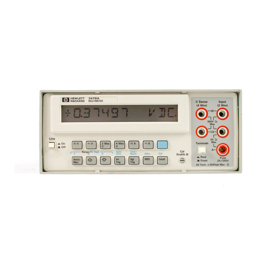
- Page 135 TM 11-6625-3071-14 TM 11-6625-3071-14 Figure 5-1. 3478A Front Panel View Figure 5-1. 3478A Front Panel View Figure 5-3. 3478A Bottom View Figure 5-3. 3478A Bottom View Figure 5-4. 3478A Left Side View Figure 5-4. 3478A Left Side View Figure 5-2. 3478A Rear Panel Vie ...
- Page 136 TM 11-6625-3071-14 TM 11-6625-3071-14 Figure 5-5. Bottom View with Cover Removed Figure 5-5. Bottom View with Cover Removed Figure 5-7. Front Panel Bracket View Figure 5-7. Front Panel Bracket View Figure 5-6. Top View with Cover Removed Figure 5-6. Top View with Cover Removed Figure 5-8.
- Page 137 Calibrati he Calibration RAM. on RAM. The 3478A The 3478A must be recalibrated, after doing the must be recalibrated, after doing the test. test.
- Page 138 7-D-18. Before troubleshooting Before troubleshooting for inoperative for inoperative HP-IB, HP-IB, make sure the 3478A is operating correctly from the make sure the 3478A is operating correctly from the front panel. front panel. Repair the fr Repair the front panel operation...
- Page 139 TM 11-6625-3071-14 TM 11-6625-3071-14 Figure 7-G-2. Figure 7-G-2. 3478A Block 3478A Block Diagram Diagram 7-G-3 7-G-3 TM 11-6625-3071-14 TM 11-6625-3071-14...
- Page 140 TM 11-6625-3071-14 TM 11-6625-3071-14 Component Locator for Input Circuitry and Ohms Current Source Component Locator for Input Circuitry and Ohms Current Source 7-G-4 7-G-4 TM 11-6625-3071-14 TM 11-6625-3071-14...
- Page 141 TM 11-6625-3071-14 TM 11-6625-3071-14 Figure 7-G-3. Figure 7-G-3. Input Input Circuitry Circuitry and Ohms and Ohms Current Source Current Source 7-G-5 7-G-5 TM 11-6625-3071-14 TM 11-6625-3071-14...
- Page 142 TM 11-6625-3071-14 TM 11-6625-3071-14 F-G-6 F-G-6 TM 11-6625-3071-14 TM 11-6625-3071-14 2 2 Figure 7-G-4. Figure 7-G-4. AC to DC Convert AC to DC Converter er 7-G-7 7-G-7 TM 11-6625-3071-14 TM 11-6625-3071-14...
- Page 143 TM 11-6625-3071-14 TM 11-6625-3071-14 2 2 Figure 7-G-4. Figure 7-G-4. AC to DC Convert AC to DC Converter er 7-G-7 7-G-7 TM 11-6625-3071-14 TM 11-6625-3071-14 Component Component Locator for A/D Converte Locator for A/D Converter and Control Logic r and Control Logic 7-G-8 7-G-8 TM 11-6625-3071-14...
- Page 144 TM 11-6625-3071-14 TM 11-6625-3071-14 Component Component Locator for A/D Converte Locator for A/D Converter and Control Logic r and Control Logic 7-G-8 7-G-8 TM 11-6625-3071-14 TM 11-6625-3071-14 Figure 7-G-5. Figure 7-G-5. A/D Converter and C A/D Converter and Control Logic ontrol Logic ...
- Page 145 TM 11-6625-3071-14 TM 11-6625-3071-14 Figure 7-G-5. Figure 7-G-5. A/D Converter and C A/D Converter and Control Logic ontrol Logic 7-G-9 7-G-9 TM 11-6625-3071-14 TM 11-6625-3071-14 7-G-10 7-G-10 TM 11-6625-3071-14 TM 11-6625-3071-14...
- Page 146 TM 11-6625-3071-14 TM 11-6625-3071-14 7-G-10 7-G-10 TM 11-6625-3071-14 TM 11-6625-3071-14 Figure 7-G-6. Power Supplies Figure 7-G-6. Power Supplies 7-G-11/(7-G-12 blank) 7-G-11/(7-G-12 blank)
- Page 147 TM 11-6625-3071-14 TM 11-6625-3071-14 Figure 7-G-6. Power Supplies Figure 7-G-6. Power Supplies 7-G-11/(7-G-12 blank) 7-G-11/(7-G-12 blank)
- Page 149 PIN NO.: NO.: 057444 057444...