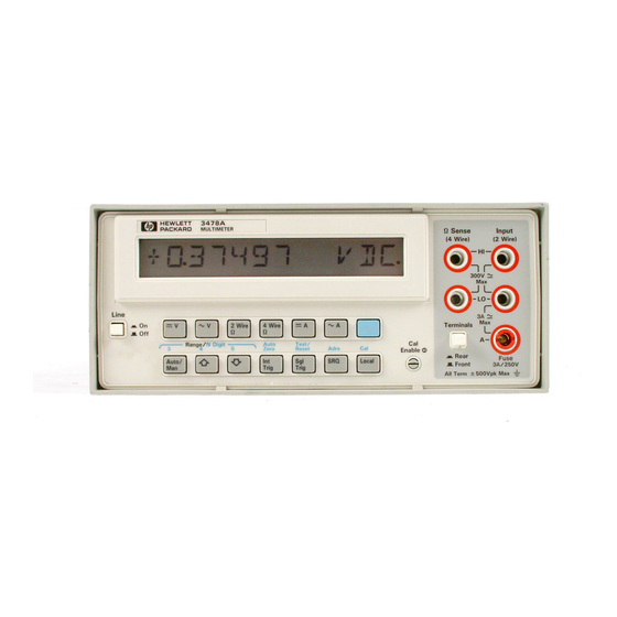
HP 3478A Technical Manual
Dilgital multimeter
Hide thumbs
Also See for 3478A:
- Service manual (160 pages) ,
- Technical manual (149 pages) ,
- Operating instructions manual (103 pages)
Table of Contents
Troubleshooting

Related Manuals for HP 3478A


Summary of Contents for HP 3478A
- Page 1 TM 11-6625-3071-14 TECHNICAL MANUAL OPERATOR’S ORGANIZATIONAL, DIRECT SUPPORT, AND GENERAL SUPPORT MAINTENANCE MANUAL DILGITAL MULTIMETER HEWLETT - PACKARD MODEL 3478A HEADQUARTERS, DEPARTMENT OF THE ARMY 5 MARCH 1985...
- Page 2 TM 11-6625-3071-14...
- Page 3 TM 11-6625-3071-14 hp-HEWLETT PACKARD SAFETY SUMMARY The following general safety precautions must be observed during all phases of operation, service, and repair of this instrument Failure to comply with those precautions or with specific warnings elsewhere in this manual violates safety standards of design, manufacture, and intended use of the instrument Hewlett Packard Company assumes no liability for the customer’s failure to comply with these requirements.
- Page 4 TM 11-6625-3071-14 C/ (D BLANK)
-
Page 5: Section Page
Washington, DC, 5 March 1985 OPERATOR’S, ORGANIZATIONAL DIRECT SUPPORT, AND GENERAL SUPPORT MAINTENANCE MANUAL DIGITAL MULTIMETER HP MODEL 3478A Serial Numbers: 2136A00101 and Greater IMPORTANT NOTICE If the Serial Number of your instrument is lower than the one on this title page, the manual contains revisions that do not apply to your instrument. - Page 6 TM 11-6625-3071-14 TABLE OF CONTENTS Section Page INTRODUCTION 0-1. Scope .............................0-1 0-2. Consolidated Index of Army Publications and Blank Forms ............0-1 0-3. Maintenance Forms, Records, and Reports ...................0-1 0-4. Reporting Equipment Improvement Recommendations (EIR) ............0-1 0-5. Administrative Storage........................0-1 0-6. Destruction of Army Electronics Materiel ..................0-1...
-
Page 7: Table Of Contents
3-69. Remote Operation ......3-8 3-70. General..........3-8 1-9. Section IV, Performance Test and 3-74. 3478A Response to Bus Messages . 3-8 Calibration 1-11. Section V, Replaceable Parts... 1-1 3-92. 3478A Addressing ......3-10 3-96. Talk-Only Mode (No Controller) ..3-10 1-13. - Page 8 Page 3-1. Shifted Operations ......... 3-6 4-8. DC Volts Calibration and Test ....... 4-13 3-2. 3478A Error Messages ........3-7 4-9. DC Current Calibration and Test ....4-15 3-3. 3478A Bus Capabilities........3-8 4-10. AC Volts Calibration and Test ....... 4-17 3-4.
- Page 9 7-D-7. JM403 SA Connection.....7-D-10 2-5. HP-IB Connector ......2-4 7-F-1. 3478A Simplified Block 2-6. 3478A Address Switch ..... 2-4 Diagram ........... 7-F-2 3-1. 3478A Front and Rear Panel 7-F-2. Simplified Schematic of the Features .......... 3-2 Input Switching Circuitry ....7-F-4 3-2.
-
Page 10: Scope
INTRODUCTION 0-1. SCOPE This manual describes the Digital Multimeter, HP Model 3478A and provides instructions for operation and maintenance. 0-2. CONSOLIDATED INDEX OF ARMY PUBLICATIONS AND BLANK FORMS Refer to the latest issue of DA Pam 310-1 to determine whether there are new editions, changes or additional publications pertaining to the equipment. -
Page 11: General Information
1-16. 3478A’s Troubleshooting Procedures, servicing to the 3478A unless you are qualified to do so. Theory Of Operation, and Schematics are in Section VII. The troubleshooting information is in the form of Service 1-1. INTRODUCTION Groups which are symptoms oriented (i.e., what is the... - Page 12 TM 11-6625-3071-14 Table 1-1. Specification...
- Page 13 TM 11-6625-3071-14 Table 1-1. Specifications. Cont.
- Page 14 TM 11-6625-3071-14 Table 1-1. Specifications. Cont.
-
Page 15: Options
Option 908: Rack Mount Kit includes one rack flange second part (suffix) identifying a particular instrument and one extension adapter (-hp- Part No. 5061-0072) within a series. An -hp- assigned alpha character l Option 910: additional set of Operators and Service between the prefix and suffix identifies the country which Manuals. -
Page 16: Installation
3478A unless you are qualified to do so. (below the power receptacle). If the instrument is incompatible with the 2-3. -
Page 17: Power Cords And Receptacles
TM 11-6625-3071-14 a. Loosen the screw on the rear of the 3478A’s top e. Reinstall the top cover. cover and remove the cover. 2-9. POWER CORDS AND RECEPTACLES b. Locate the Line Select wire and the line 2-10. Figure 2-3 illustrates the different power plug terminals. -
Page 18: Rack Mounting
Figure 2-5 for the factory address setting of the switch. instructions for rack mounting is contained in the kit. The kit is designed to permit the 3478A to be mounted in a Refer to the Remote Operation Chapter in Sec- tion III of... -
Page 19: Repackaging For Shipment
Seal the carton with strong tape or metal In any correspondence, identify the instrument bands. by model number and full serial number. If you have any questions, contact your nearest -hp- d. Mark shipping container "DELICATE INSTRU- Sales/Service office. MENT", "FRAGILE", etc. -
Page 20: Operation
Input Terminals Cleaning 3-15 displayed for abour l/4 second. When the test is b. Front Panel Operation - paragraph 3-17. completed and the 3478A passes the test, the 3478A’s Title Paragraph remote (HP-IB) address will be displayed for about one... -
Page 21: 3478A Front And Rear Panel Features
The Test/Reset key performs an internal self test, then 6. This is the Amps input terminal and is used with the resets the 3478A to its turn-on state. Any errors in the INPUT LOW terminal. 13 Amp fuse protected) self test are noted in the display. -
Page 22: Front Panel Operation
Function for dc volts measurements by pressing the =v button. 3-20. In the DC Volts Function, ranging is done in the Input Circuitry of the 3478A. The result is that the input to the A/D Converter (which changes the voltage to digital information) has the same value in all ranges for Figure 3-2. -
Page 23: Ac Volts Measurements
The AC to DC Converter changes the ac input voltage to dc volts, which is then measured by the 3478A’s A/D Converter. All ranging is done in the AC to DC Converter, applying the same voltage value to the A/D Converter for all full scale inputs. -
Page 24: Dc Current Measurements
Resistor) value to change slightly, range when this mode is selected. The mode is selected due to self-heating. This may cause when the 3478A is first turned on or by pressing the inaccuracies measurement. AUTO/MAN button (if in Manual Range). If Autorange is... -
Page 25: Shifted Operation
SHIFTED OPERATION 3-51. General 3-52. The Shifted Operation of the 3478A is used to expand the capabilities of the multimeter using the same number of front panel pushbuttons. This is done by using the bottom row of front panel buttons for two different operations, shifted and unshifted. -
Page 26: Autozero
Since no more offset readings are taken, the reading rate of the 3478A is faster (up to twice as fast). If a 3-63. Calibration range, function, or digit change is made, or an at- tempt is made to calibrate the 3478A, a new offset reading is 3-64. -
Page 27: Miscellaneous Operations
3-114 Directions for mechanical interface connections to the Front Panel SRQ 3-115 HP-IB are given in Section II of this manual. Familiarize Fast Trigger 3-116 yourself with the front panel operation (local) before attempting to use the multimeter in remote (HP-IB). -
Page 28: Status Byte
This includes the Message is cleared. multimeter’s output (readings) and status information. In this case, the 3478A is the Talker and the controller is 3-83. Require Service (SRQ). The Require Service the Listener. Message (SRQ Message) is independent of all other HPIB activity and is sent on a single line called the SRQ 3-77. -
Page 29: 3478A Addressing
"listen" and "talk" address. The address of pressed. See paragraph 3-115. the 3478A is set by the Address Switch on its rear panel. Setting the 3478A’s Listen Address also sets its Talk Address. Invalid Calibration - When this bit is set, an attempt to calibrate the 3478A has failed. -
Page 30: 3478A Hp-Ib Programming
(e.g. "IF" causes a Syntax Error). 3-103. Programming the SRQ Mask. The SRQ Mask must be set for the 3478A to output a Require Service Message. Setting the SRQ Mask will not set the bits in the Status Byte;... -
Page 31: A Program Codes
Home Commands. The Home Commands Clears Status Register (when sent to the 3478A over the HP-IB) are used to set Set SRO Mask (Mdd, where dd is the octal code of the 3478A into a predefined operating state. the bits) program code is "Hn", where n is the number which,... - Page 32 (D.DDDDD, DD.DDDD, or DDD.DDD). If b. HI Command (DCV). This command is the same the 3478A is in the 4 1/2 or 3 1/2 Digit mode, the 5th as the "HO” command, except a trigger occurs and the resultant output can be read.
-
Page 33: Advanced Programming
TM 11-6625-3071-14 3478A 3-116. Fast Trigger. This trigger mode can only be selected over the HP-IB. It is the same as the Single Table 3-7. Binary Status Byte Definition Trigger, except the delays in the AC Volts Function, AC Byte #... -
Page 34: Performance Test And Calibration
It is recommended that the Digital Voltmeter be calibrated in the same temperature environment and leave DC Carrot Function (accuracy = ±(% of reading + number of counts) it in the environment in which the 3478A is to be calibrated Range 90 Day Limits 1 Year Limits and tested (e.g. -
Page 35: Ac Volts Test And Calibration
It is recommended to acquire in series, to form 300, 3000, etc. If the 3478A is to be the recommended calibrator with the HP-IB (IEEE 488) tested and calibrated at 1/3 scale, use only one each of option 05 for future computerized Performance Tests the recommended standard resistors. -
Page 36: Dc Current Test And Calibration
4-25. Performance Test Cards are provided at the end requirement is + .0005°o or better. of this section and are to be used to record the 3478A's b. 10K ohm and 100K ohm Standard Resistors. performance. It is recommended to fill out the cards and Use the Guildline Model 9330/10K or 9330A/O1K for the refer to them while doing the test. -
Page 37: Specification Breakdown
Although in both instances the Digit Display Mode is selected, the percentage is the standard is within its limits, it may show the 3478A to be same (.005%o), but the number of counts is different and in or out of its limits. -
Page 38: Performance Test
Each step on the test card corresponds to a step in the test procedure. d. (Step #3, 4, 5, and 6.) Set the 3478A to the 300mV, Because of this, each step number on the test card is 3V, 30V, and 300V Range by pressing the Uprange shown in parenthesis (e.g., Step #1.) in the procedure. -
Page 39: Dc Volts Accuracy Test And Calibration
3478A’s INPUT Terminals and set the multimeter to the 30mV Range. i. (Step #9.) Set the 3478A to the 3V Range and set the DC Volts Standard for an accurate output of + f. Set the DC Volts Standard for zero volts output. Set 300mV. -
Page 40: Dc Current Test
Current Test Card and in Table 4-4. Each step on the test card also corresponds to a step in the procedure d. (Step #3.) Set the 3478A to the 3A Range. Check with each step number shown in parenthesis in the and record the reading. -
Page 41: Ac Volts Test
Make sure the reading on the Digital Voltmeter b. (Step #2.) Set the 3478A to the AC Volts Function. exactly + IV. Readjust the DC Volts Standard necessary. c. Set the AC Calibrator for a .03V at 20KHz output. -
Page 42: Ac Current Test
Section VII for Volts Performance Test Card. Record the readings. troubleshooting. e. (Step #5, 6, and 7.) Set the 3478A to the 3V Range. 4-64. AC Current Test Check the 1/10, 1/2, and full scale accuracy of the range by applying 0.3V at 20KHz, 1.5V at 20KHz, and 3V at... -
Page 43: Ohms Test.4-10
AC-DC Current Calibrator to the IA Range. Check and record the 3478A’s reading. 4-72. If the 3478A is to be tested in the 2-Wire Ohms Function, all test resistors are applied to the 3478A’s j. Remove the AC Calibrator from the AC-DC Current INPUT Terminals. -
Page 44: Combined Calibration And Performance Tests
The following paragraphs have the 3478A’s Combined Calibration Procedures and Performance c. (Step #3, 4, 5, 6, 7, and 8.) Set the 3478A to the Tests. The Performance Tests are included in the 3001, 3K1], 3Knl, 300Knl, 3Mn, and 30M1l Range by procedures since they are normally performed after pressing the Uprange button once for each range. -
Page 45: Calibrating The 3478A
(or 1/3 scale) value by more than + 7%. The calibration is performed as a. Set the 3478A to the DC Volts Function and the 3V follows: Range. Make sure the instrument is not in Autorange. -
Page 46: Calibration Messages
Test for full scale (or in some cases 1/3 scale) and zero panel CAL ENABLE switch is not in the enable position inputs are not included. This is because the 3478A is (the slot of the switch is horizontal) when attempting to normally calibrated using full scale (or 1/3 scale) and calibrate the multimeter. - Page 47 2. Use the Digital Voltmeter as the standard and the DC Volts Standard as a stable power supply. 6. (Step #10.) Apply -3V to the 3478A by setting the DC Volts Standard for a 3V output. Check the reading. i. Set the DC Volts Standard’s output for + 30mV and note the reading on the Digital Voltmeter.
-
Page 48: Dc Current Calibration And Test
Digital Voltmeter from the 3478A. s. (Step #15 and 16.) Short the 3478A’s HI and LO z. If the DC Common Mode Rejection Test is to be INPUT Terminals. Set the instrument to the 30V Range. -
Page 49: Ac Volts Calibration And Test
3478A by doing the procedure in steps f and (CAL) button. Using the 3478A’s Uprange and/or Downrange p. (Step #4.) Set the 3478A to the 3A Range and the buttons, adjust the reading on the multimeter until it AC-DC Calibrator to the IA Range. -
Page 50: Ac Volts Calibration And Test
.3V at 20KHz to the multimeter. respectively. Check the readings. l. (Step #4, 5, and 6.) Set the 3478A to the 3V Range. (Step #20.) Set the 3478A to the 300V Range. Check the 1/10, 1/2, and full scale accuracy of the range Check the full scale accuracy of the range by applying by applying 0.3V at 20KHz, 1.SV at 20KHz, and 3V at... -
Page 51: Ac Current Calibration And Test
Standard Resistors to the 3478A’s HI and b. Make sure the front panel CAL ENABLE Switch is LO INPUT Terminals. If the 3478A is to be calibrated in set to the calibration enable position (the slot of the the 4-Wire Ohms Function, connect the Standard switch is in the vertical position). -
Page 52: Ohms Calibration And Test
Press the blue Shift button and then the LOCAL (CAL) button. j. Press the SGL/TRIG button once. k. (Step #3 and 4.) Set the 3478A to the 300(2 Range and calibrate the range using zero and full scale (or 1/3 scale) inputs. - Page 53 TM 11-6625-3071-14...
- Page 54 TM 11-6625-3071-14...
- Page 55 TM 11-6625-3071-14...
- Page 56 TM 11-6625-3071-14...
- Page 57 TM 11-6625-3071-14 PERFORMANCE TEST CARD 1 YEAR LIMITS Hewlett-Packard Model 3478A Test Performed By______________________ Digital Multimeter Date_____________ Serial Number_____________ Reference Temperature__________________ AC Volts Test Step# Input to Set-Up and High Reading Test Test 3478A Configuration Limit Limit Pass Fail Open...
- Page 58 TM 11-6625-3071-14 PERFORMANCE TEST CARD 1 YEAR LIMITS Hewlett-Packard Model 3478A Test Performed By______________________ Digital Multimeter Date_____________ Serial Number_____________ Reference Temperature__________________ AC Current Test Step# Input to Set-Up and High Reading Test Test 3478A Configuration Limit Limit Pass Fail Open...
- Page 59 TM 11-6625-3071-14 PERFORMANCE TEST CARD 1 YEAR LIMITS Hewlett-Packard Model 3478A Test Performed By______________________ Digital Multimeter Date_____________ Serial Number_____________ Reference Temperature__________________ Ohms Test Step# Input to Set-Up and High Reading Test Test 3478A Configuration Limit Limit Pass Fail Open Press TEST/RESET...
- Page 60 TM 11-6625-3071-14 PERFORMANCE TEST CARD 1 YEAR LIMITS Hewlett-Packard Model 3478A Test Performed By______________________ Digital Multimeter Date_____________ Serial Number_____________ Reference Temperature__________________ Ohms Test Step# Input to Set-Up and High Reading Test Test 3478A Configuration Limit Limit Pass Fail Open Press TEST/RESET...
- Page 61 TM 11-6625-3071-14 PERFORMANCE TEST CARD 1 YEAR LIMITS Hewlett-Packard Model 3478A Test Performed By______________________ Digital Multimeter Date_____________ Serial Number_____________ Reference Temperature__________________ Ohms Test Step# Input to Set-Up and High Reading Test Test 3478A Configuration Limit Limit Pass Fail Open Press TEST/RESET...
-
Page 62: Replaceable Parts
Table 5-3 lists the parts in 5-6. NON-LISTED PARTS alphameric order of their reference designators and indicates the description, -hp- Part Number of each part, together with any applicable notes, and provides the 5-7. To obtain a part that is not listed, include: following: a. -
Page 63: 3478A Disassembly Procedure
(MP13). c. Turn the 3478A right side up. Remove the top cover by pulling the cover toward the rear of the 3478A m. Remove the front frame (MP13) by pulling the and away from the multimeter. - Page 64 Replaceable Parts TM 11-6625-3071-14 Table 5-3. Replaceable Parts Reference HP Part C Qty Description Mfr Part Number Designation Number Code 03478-66501 PC ASSEMBLY-MOTHER BOARD 28480 13478-66501 A1BT701 1420-0278 BATTERY 3V .95A-HR LI/S-DIOX W-FLEX 28480 1420-0278 A1C101 0160-4438 CAPACITOR-FXD 470PF +-2.5% 160VDC P0LYP...
- Page 65 A1H703 1205-0318 HEAT SINK SGL TO-220-CS 28480 1205-0318 A1J504 1200-0583 SOCKET-IC 24-C0NT DIP DIP-SLDR 28480 1200-0583 A1J702 1251-4743 CONNECTOR-AC PWR HP-9 MALE REC-FLG THRMP 28480 1251-4743 A1J527 1200-0853 SOCKET-IC 16 C0NT DIP DIP-SLDR 28480 1200-0853 A1JM403 1258-0141 JUMPER-REM 28480 1258-0141...
- Page 66 Replaceable Parts TM 11-6625-3071-14 Table 5-3. Replaceable Parts Reference HP Part Description Mfr Part Number Designation Number Code A1R403 0698-4539 RESISTOR 402K 1% .125W F TC=D+-100 28480 0698-4539 A1R404 0757-0472 RESISTOR 200K 1% .125W F TC=0+-100 24546 C4-1/8-T0-2003-F A1R405 0757-0465 RESISTOR 100K 1% .125W F TC=0+-100...
- Page 67 Replaceable Parts TM 11-6625-3071-14 Table 5-3. Replaceable Parts Reference HP Part C Qty Description Mfr Part Number Designation Number Code A1U465 1820-2258 IC FF CM0S D-TYPE POS-EDGE-TRIG COM 04713 MC14174BCP A1U466 1820-0935 IC CNTR CMOS BIN NEG-EDGE-TRIG 14-B1T 0192B CD4020BE...
- Page 68 Replaceable Parts TM 11-6625-3071-14 Table 5-3. Replaceable Parts Reference HP Part Description Mfr Part Number Designation Number Code A1 MISCELLANEOUS PARTS 1600-0273 SHIELD-RF 28480 1600-0273 CHASSIS MOUNTED PARTS C764 0160-4571 CAPACITOR-FXD .1UF +80-20% 50VDC CER 28480 0160-4571 S760 03478-61901 POWER SWITCH ASSY...
-
Page 69: 3478A Mechanical And Miscellaneous Parts
TM 11-6625-3071-14 Table 5-4. 3478A Mechanical and Miscellaneous Parts Ref. Part Des. Number Qty. Description 0370-0603 Pushbutton (Power Switch) 0370-0604 Pushbutton (Front/Rear Switch) 03478-60201 Front Panel Assembly 5060-9905 Side Cover 5061-1164 Binding Post 5060-9839 Top Cover 03478-00202 Rear Panel 0380-1270... -
Page 70: Backdating
TM 11-6625-3071-14 SECTION VI BACKDATING 6-1. INTRODUCTION 6-2. This section has information which adapts this manual to instruments with serial numbers below the ones shown on the title page. Since this manual does directly apply to instruments having serial numbers listed on the title page, no change information is given here. -
Page 71: Service
Calibration, maintenance, or repair of the instrument with covers removed while any power or 7-14. The 3478A has two fuses, one fuse is the main voltage is applied, should be avoided as much as power fuse and the other one is to protect the instrument possible. -
Page 72: Troubleshooting
Control ROM Fails (U.C. ROM FAIL). This a. Main Power Fuse. To replace the main power indicates that the 3478A has failed its internal ROM self fuse, first remove power from the 3478A. With a test. The Control ROM (U502) is the most likely cause. -
Page 73: Dc/Ohms Input Amplifier
7-29. The correct Service Group is selected according to c. Floating Reading. A floating reading is when failure. Once the failure has been determined, go to the the 3478A displays a certain reading (with no input applied) which does not change, after an input is applied recommended group. - Page 74 Failures). Inoperative Keyboard. An Inoperative Keyboard is when part or all of the 3478A’s keyboard is b. A/D Slope Error. This failure can be caused by inoperative. This can be caused by the keyboard itself or the A/D Converter or the A/D Controller and shows up as the Main Controller Circuitry.
- Page 75 -14.4V to -15.6V two different levels of troubleshooting. The first level +15V JM703 +14.4V to +15.6V determines the general area of the 3478A that causes failure second level specific b. Check and make sure the Reference Supplies troubleshooting information for the area that fails.
- Page 76 Before replacing U102, make sure the A/D Controller (U462) is good. Go to paragraph 7-A-33 a. Set the 3478A to the DC Volts Function and the for the SA procedure to check U462, before replacing the 3V Range.
- Page 77 If the displayed reading on the 3478A is still a floating reading, replace U101. 7-A-25. Constant Zero Readings on All Ranges f. If the displayed reading on the 3478A is + 3V, the 7-A-26. A constant zero reading is normally caused Input Hybrid (U102) may be at fault.
- Page 78 TM 11-6625-3071-14 Hybrid or the DC/Ohms Input Amplifier. Do the following: 7-A-33. CHECKING THE A/D CONTROLLER (U482) a. Set the 3478A to the DC Volts Function and the 3V Range. 7-A-34. Do the following to check the A/D Controller. Refer to Schematic 3.
-
Page 79: Ac Volts And Ac Current Troubleshooting
7-B-16 to check U462. If K104 is good, do the following procedure. CAUTION a. Set the 3478A to the AC Volts Function and the The instrument contains CMOS Integrated 3V Range. Circuits (e.g. U102) which are extremely... - Page 80 Ground Pin (next to C203) 7-B-9. Since the 3478A’s AC to DC Converter is d. Turn the 3478A on and check for the following calibrated with an input voltage at a frequency of 1KHz, signatures. inaccuracy can result from poor frequency response.
-
Page 81: Ohms Troubleshooting
Do the following procedure. CAUTION a. Set the 3478A to the 2-Wire Ohms Function and the 3K ohm Range. The instrument contains CMOS Integrated Connect a 3K ohm Resistor to the 3478A’s Circuits (e.g. - Page 82 Set the 3478A to the 2-Wire Ohms Function and 2. If the Ohms Function is now operating, check the 3K ohm Range.
- Page 83 To check the circuitry operation for positive input procedure. voltages, do the following: a. Set the 3478A to the 2-Wire Ohms Function and 1. Set the 3478A to the 2-Wire Ohms Function the 3K ohm Range. and the 3K ohm Range.
- Page 84 If the Ohms Current Source is still inoperative, replace U203 and then U102. Figure 7-C-1. JM403 SA Connection 7-C-22. 4-WIRE OHMS TROUBLESHOOTING Turn the 3478A on and check the following 7-C-23. The only difference between the two ohms signatures:...
-
Page 85: Circuitry
It is especially important that grounded tools and wrist straps be used when 7-D-3. The 3478A Logic Circuitry can be separated into handling or troubleshooting these components. two major circuitry: Chassis Common Logic Circuitry and Floating Common Logic Circuitry. The Chassis Common 7-D-5. -
Page 86: Flowchart
HP-IB is inoperative. It may not be necessary to check for an HP-IB failure if the two previous symptoms b. Move jumpers JM502 and JM503 to the "D" were are noted. If only an HP-IB failure is noted, go to position. paragraph 7-D-17 for troubleshooting. - Page 87 TM 11-6625-3071-14 3478A Figure 7-D-3. Flowchart B 7-D-5...
- Page 88 TM 11-6625-3071-14 3478A Figure 7-D-4. Flowchart C 7-D-6...
- Page 89 1.Check for a low at pin 4 of U514. from it. One caution when checking the RAM, the data in the RAM will be lost and the 3478A will need to be 2.If pin 4 of U514 is low, replace U514.
- Page 90 If it has not been performed, do the following: d. Turn the 3478A on and check for the following signatures: a. Set the 3478A to the DC Volts Function and 3V U462 pin 32: 7ACA Range. U462 pin 33: 20FO U462 pin 34: 666H b.
- Page 91 TM 11-6625-3071-14 3478A Figure 7-D-6. Flowchart D 7-D-9...
- Page 92 RESET line toggles from high to low to high. g. If the SA probe is not toggling (the signature can d. If the RESET line toggles and the 3478A is still be the same or different), the isolation circuitry is defec- in- operative, replace U462.
-
Page 93: Power Supplies
7-E-12. A high supply is most likely caused by the regulators (U702 or U703) 7-E-4. The Floating Common Section of the 3478A has three power supplies which are: + 5V, -15V, and + 15V. 7-E-13.REFERENCE CIRCUITRY The Chassis Common Section has one + 5V supply. - Page 94 TM 11-6625-3071-14 3478A c. If both + 10V and -10V voltages are good and 1. Check for a quiet -10V at pin 2 of U402. the buffered + 10V is is low, lift jumper JM201 (see Schematic 1). If the + 10V is now good, replace U102. If 2.
- Page 95 The Main Controller also Model 3478A Multimeter. The general description ex- sends information to the display to show the selected plains the purpose of each operating block of the 3478A Simplified Block Diagram (shown in Figure 7-F-I). The function and range.
- Page 96 TM 11-6625-3071-14 3478A Figure 7-F-1. 3478A Simplified Block Diagram c. Ohms Function. If the Ohms Function is zero measurement (see step calibration constant(s). selected, the Ohms Current Source supplies a known dc current to the unknown resistance. A voltage drop proportional to the unknown resistance and the current is e.
-
Page 97: Ac To Dc Converter
7-F-11. General. The purpose of the Input Circuitry is to 1 for the explanation. condition the dc input signals to the 3478A to provide full scale 10V dc input voltages to the A/D Converter, for full scale inputs to the 3478A (the explanation for ac inputs a. - Page 98 TM 11-6625-3071-14 3478A Figure 7-F-2. Simplified Schematic Of The Input Switching Circuitry 7-F-4...
- Page 99 RI01, R102, and S6ADC and S6CDC (S6ADC and S6CDC are in U102). The path is used to ment, the input to the 3478A is applied to the Input Amplifier and the capacitor is charged to the input connect the LO OHMS SENSE Input Terminal (low ohms voltage.
- Page 100 TM 11-6625-3071-14 3478A the positive terminal of Buffer U202. The reference out- put, which is applied to the positive terminal of the Out- put FET Control Amp U203, is divided down to + 8V, irrespective of range, by feedback resistors RR3 and RR4 in conjunction with R206.
- Page 101 7-F-26. The purpose of the AC to DC Converter is to its output at either + 12V or + 8.4V (on the 30M convert the 3478A’s ac inputs (volts or current) to dc volts. The converter output is + 3.00000V dc for all full- scale ac inputs with the output applied to the A/D Con- Table 7-F-1.
- Page 102 TM 11-6625-3071-14 3478A verter. All ac ranging is done in the AC to DC Con- a. The first amplifier stage (U301A) is an inverting verter. amplifier with gains of X.00, X. 1, or XI (dependent on the ac range and function selected).
- Page 103 Reference (U461 and associated circuitry), and the A/D Hybrid (U403). The A/D Converter operation is controlled by the A/D Controller (U462). 7-F-33. The A/D conversion method used by the 3478A is called Multi-Slope II and has two operating states: Runup and Rundown. The 3478A’s most significant...
- Page 104 3478A’s reading is calculated. 7-F-37. Detailed Explanation of Runup. Figure 7-F-9 illustrates the 3478A runup operation in the 4 1/2 digit mode. Refer to the figure (and Schematic 3) for the runup explanation in the following steps. The solid lines (in the figure) showing the runup sequence is for a Figure 7-F-8.
- Page 105 TM 11-6625-3071-14 3478A Figure 7-F-9. Runup Slopes (4 ½ Digit Model) hypothetical input value. The dashed lines are for a e. When time T2 is completed, an S + 4 current is larger hypothetical input value. applied for 30 ALE cycles (36 ALE cycles for the 50Hz a.
- Page 106 TM 11-6625-3071-14 3478A Figure 7-F-10. Runup Slopes for Zero Inputs (41/2 Digit Model) slopes. For a perfect zero reading, the number of S + 4 resistor and paths Y1 and Y2 to -Vref. Current also flows slopes will be the same as the number of S-4 slopes.
-
Page 107: Slopes
When rundown starts, the polarity of the 7-F-41. Digit Generation. When the 3478A is in the 4 remaining voltage on the integrator is determined by the 1/2 and 5 1/2 Digit mode, the first two significant digits A/D Controller (U462). - Page 108 Both the slope and zero. This is then used to calculate the three least the integrator voltage together could saturate the significant digits of the 3478A’s reading. integrator. When Current S-4 is removed, no current (an 7-F-46. Integrator Offset Compensation.
- Page 109 TM 11-6625-3071-14 3478A 7-F-49. A/D Converter and Reference Circuitry. The A/D Converter Circuitry consists of the A/D Hybrid (U403), A/D Integrator (U401 and associated circuitry), A/D Controller (U462), and a DAC (U465 and associated circuitry). Since the Voltage Reference Cir- cuitry (U461,...
- Page 110 (S-4, S + 4, etc.). Refer to 7-F-50. 3478A Logic Circuitry 7-F-51. General. The 3478A Logic Circuitry can be divided into two circuit areas: Chassis Common Cir- 7-F-15...
- Page 111 TM 11-6625-3071-14 Figure 7-F-17. 3478A Simplified Reference Circuitry 7-F-16...
-
Page 112: Power-On Circuitry
Schematic 3 and 4. The Power-On Circuitry resets the e. CPU Reset Operation - paragraph 7-F-81. CPU when the 3478A is turned on and when +SV power Front/Rear Switch Position - paragraph 7-F-82. supply is low. The step by step operation is as follows: 7-F-55. -
Page 113: Reset Circuitry
7-F-61. RAM Addressing. The RAM can only be addressed as long as line CE2 (Chip Enable 2 at U512 pin 17) is high. The line is high when the 3478A is turned on. Line CEI (Chip Enable I at U512 pin 19) can be high or low. -
Page 114: List
Data when its R/W line (Read/Write at U5 button is pressed and turns the corresponding SRQ 12 pin 20) is low. This can only happen if the 3478A’s switch on. This connects Port P11 to P17 and makes Cal Enable Switch (located on the front panel) is on and P11 high when P17 is high. - Page 115 CPU checks the state of the INT line. If the line is high, Status Bit, set the 3478A to the Talk-Only Mode, and to the 3478A is triggered. If the line is low, the CPU keeps set the multimeter to the selected power line frequency.
- Page 116 (U462) whenever needed. This is normally done when the Digital to Analog Converter, and to send set-up the 3478A is turned on. The operation is as follows. (Range and Function) information to the Input Hybrid U102 (see paragraph 7-F-13 for its operation and Counter U466 increments each time it is purpose).
- Page 117 CR714, respectively. The diodes conduct if the raw (unregulated) voltage is too large. Capacitors C702, 3478A is turned on, the CMOS RAM receives its supply voltage (+ SV) from regulator transistor Q701. The raw C703, and C706 are filter capacitors. Temperature...
-
Page 118: Schematics
Power Supplies (Schematic 4) ......7-G-6 Diagram and Schematics. In addition, general 7-G-1. INTRODUCTION schematics notes are also included to gain an under- standing on how to use the schematics. 7-G-2. This Service Group has the 3478A’s Block Figure 7-G-1. General Schematic Notes 7-G-1/(7-G-2 blank) - Page 119 HP-IB. c. Device: A unit that is compatible with the IEEE A-5. The HP-IB is a parallel bus of 16 active signal lines Standard 488-1978. grouped into three sets, according to function, to interconnect up to 15 instruments.
-
Page 120: Interface Connection And Bus Structure
Clear: The Clear message causes the listening two types of controllers, an Active Controller and a System device(s) or all the devices on the HP-IB to return to their Controller. The Active Controller is the current controlling predefined device-dependent state. -
Page 121: A-2. Hp-Ib Worksheet
The message will terminate all controller and for each HP-IB device. The bus capability bus communication but does not implement the CLEAR for the 3478A has already b, en filled in. Refer to your message. controller manual and the manual(s) of your other device(s) for their Bus Message capabilities. - Page 122 TM 11-6625-3071-14 Table A-2. A-2 HP-IB Worksheet...
- Page 123 (TAMMS). TM 11-6625-3071-24P Organizational, Direct Support and General Support Maintenance Manual, Including Repair Parts and Special Tools List for Digital Multimeter, HP Model 3478A. TM 750-244-2 Procedures for Destruction of Electronics Materiel to Prevent Enemy Use (Electronics Command). B-1/(B-2 blank)
- Page 124 COMPONENTS OF END ITEM LIST Section 1. INTRODUCTION C-1. Scope The appendix lists integral components of and basic issue items for Digital Multimeter, HP Model 3478A to help you inventory items required for safe and efficient operations, C-2. General This components of End Item List is divided into the following sections: a.
- Page 125 TM 11-6625-3071-14 area of the major item before moving in to an adjacent area. Usable on Code. Not applicable. Quantity Required (Qty Reqd). This column lists the quantity of each item required for a complete major item. Quantity. This column is left blank for use during the inventory. Under the Revd column, list the quantity you actually receive on your major item.
- Page 126 TM 11-6625-3071-14 Section II INTEGRAL COMPONENTS OF END ITEM ILLUSTRATION NATIONAL DESCRIPTION LOCATION USUABLE QUANTITY STOCK REQD FIG. ITEM NUMBER PART NUMBER FSCM CODE RCVD DATE DIGITAL MULTIMETER, HP3478A C-3/(C-4 blank)
- Page 127 Section 1. INTRODUCTION C-1. General This appendix provides a summary of the maintenance operations for the Digital Multimeter, HP Model 3478A. It authorizes categories of maintenance for specific maintenance functions on repairable items and components and the tools and equipment required to perform each function. This appendix may be used as an aid in planning maintenance operations.
- Page 128 TM 11-6625-3071-14 q. Install. The act of emplacing, seating, or fixing into position an item, part, module (component or assembly) in a manner to allow the proper functioning of the equipment or system. h. Replace. The act of substituting a serviceable like type part, subassembly, or module (component or assembly) for an unserviceable counterpart.
- Page 129 TM 11-6625-3071-14 b. Column 2, Component/Assembly. Column 2 contains the noun names of components, assemblies, subassemblies, and modules for which maintenance is authorized, c. Column 3, Maintenance Functions. Column 3 lists the functions to be performed on the item listed column 2. When items are listed without maintenance functions, it is solely for purpose of having the group numbers in the MAC and RPSTL coincide.
- Page 130 TM 11-6625-3071-14 D-4. Tool and Test Equipment Requirements (Sec III) a. Tool and Test Equipment Reference Code. The numbers in this column coincide with the numbers used in the tools and equipment column of the MAC. The numbers indicate the applicable tool or test equipment for the maintenance functions.
- Page 131 TM 11-6625-3071-14 SECTION II MAINTENANCE ALLOCATION CHART DIGITAL MULTIMETER HP3478A Group Maint. Maint. category Tool/ number Component/assembly function equipment Remarks DIGITAL MULTIMETER Inspect HP3478A Test 1-4, 6-9 Test Calibrate Replace Repair Repair MOTHERBOARD PCB, Inspect 03478-66501 Replace Repair Test...
- Page 132 TM 11-6625-3071-14 SECTION-III TOOL AND TEST EQUIPMENT REQUIREMENTS DIGITAL MULTIMETER HP3478A SECTION III TOOL AND TEST EQUIPMENT REQUIREMENTS TOOL OR TESTMAINTENANCE NATIONAL/ TOOL EQUIPMENT CATEGORY NOMENCLATURE NATO STOCK NUMBER REF CODE NUMBER DIGITAL VOLTMETER, 6625-00-022-7894 AN/GSM-64B DC VOLTAGE STANDARD, SYSTRON DONNER M107 AC CALIBRATOR, FLUKE MODEL 5200A AND MODEL 5215A...
- Page 133 TM 11-6625-3071-14 SECTION IV. REMARKS DIGITAL MULTIMETER HP3478A REFERENCE CODE REMARKS Test, calibrate, and repair by USATSG at general support. Repair consists of replacement of subassemblies and mainframe components as required. Cable assembly W502 and battery BT701 are throw-away items. D-7/(D-8 blank)
- Page 134 By Order of the Secretary of the Army: JOHN A. WICKHAM JR. General, United States Army Chief of Staff Official: DONALD J. DELANDRO Brigadier General, United States Army The Adjutant General Distribution: To be distributed in accordance with special list.
-
Page 135: 3478A Front Panel View
TM 11-6625-3071-14 Figure 5-1. 3478A Front Panel View Figure 5-3. 3478A Bottom View Figure 5-4. 3478A Left Side View Figure 5-2. 3478A Rear Panel View 5-9/(5-10 blank) -
Page 136: Front Panel Bracket View
TM 11-6625-3071-14 Figure 5-5. Bottom View with Cover Removed Figure 5-7. Front Panel Bracket View Figure 5-6. Top View with Cover Removed Figure 5-8. Front Panel Assembly 5-11/(5-12BLANK) - Page 137 TM 11-6625-3071-14 Figure 7-D-2. Flow chart A 7-D-3...
- Page 138 Connect and set the Signature Analyzer as follows: 7-D-18. Before troubleshooting for inoperative HP-IB, make sure the 3478A is operating correctly from the front panel. Repair the front panel operation first, before troubleshooting for an Hp-IB failure. To troubleshoot an HP-IB failure, go to Flowchart C.
- Page 139 TM 11-6625-3071-14 Figure 7-G-2. 3478A Block Diagram 7-G-3...
- Page 140 TM 11-6625-3071-14 Component Locator for Input Circuitry and Ohms Current Source 7-G-4...
- Page 141 TM 11-6625-3071-14 Figure 7-G-3. Input Circuitry and Ohms Current Source 7-G-5...
- Page 142 TM 11-6625-3071-14 F-G-6...
- Page 143 TM 11-6625-3071-14 Figure 7-G-4. AC to DC Converter 7-G-7...
- Page 144 TM 11-6625-3071-14 Component Locator for A/D Converter and Control Logic 7-G-8...
- Page 145 TM 11-6625-3071-14 Figure 7-G-5. A/D Converter and Control Logic 7-G-9...
- Page 146 TM 11-6625-3071-14 7-G-10...
- Page 147 TM 11-6625-3071-14 Figure 7-G-6. Power Supplies 7-G-11/(7-G-12 blank)
- Page 149 PIN NO.: 057444...
- Page 150 This fine document... Was brought to you by me: Liberated Manuals -- free army and government manuals Why do I do it? I am tired of sleazy CD-ROM sellers, who take publicly available information, slap “watermarks” and other junk on it, and sell it. Those masters of search engine manipulation make sure that their sites that sell free information, come up first in search engines.