
Related Manuals for JDS Uniphase cOPM-A1


Summary of Contents for JDS Uniphase cOPM-A1
- Page 1 Optical Power Meter Operating Manual BN 2297/02 BN2297/98.12 2008.11 English...
- Page 2 ITU-T and/or ETSI. © Copyright 2008 JDSU Deutschland GmbH. All rights reserverd. JDSU and JDSU logo are trademarks of JDS Uniphase Corporation. Other trademarks are the property of their respective holders.
-
Page 3: Table Of Contents
NTRODUCTION cOPM-A1 Optical Power Meter ....1 Operating manual update ....2 Symbols used in this operating manual . - Page 4 Accessories ......50 ......51 NDEX JDSU cOPM-A1...
-
Page 5: Introduction
The Compact Photonic Tools are stackable, so you can assemble individual test sets. Common features The cOPM-A1 offers a new portfolio of point solutions for fiber optic test applications. The cOPM-A1 Optical Power Meter is optimized for a number of applications ranging from general lab use to test and process automation for passive optical components. -
Page 6: Operating Manual Update
NTRODUCTION Innovative features Auto dark current The cOPM-A1 removes the need for manual dark current measurements through innovative analogue circuit design. Typical power meters must be routinely and manually terminated to measure residual current from the photodiode. If this termination is not performed,or performed poorly, significant errors can result for low power measurements. -
Page 7: Symbols Used In This Operating Manual
This safety instruction is given if the danger is due to laser radiation. Information specifying the laser class is also given. Very important instruction Follow this instruction carefully; e.g. Make sure you protect yourself and others from exposure to laser light. JDSU cOPM-A1... - Page 8 Cross references Text in blue Cross references are indicated in blue type. When using the PDF version, just click on the blue text to skip to the cross reference. Instrument keys [Store] Instrument keys are indicated within square brackets. cOPM-A1 JDSU...
-
Page 9: Afety Nformation
⇒ Please make sure the device is not operated outside the permitted ambient conditions. ⇒ Observe the specified measurement range. ⇒ Always make sure that the device is in proper working order before switching it on. JDSU cOPM-A1... -
Page 10: Laser Safety
Laser radiation can cause irreparable damage to the eye and skin. WARNING The maximum permitted power for the cOPM-A1 means that the optical input signals can reach Hazard Level 4, depending on the device type. Bear this in mind when using the cOPM-A1. -
Page 11: Snt-121A Adapter
If condensation cannot be avoided, such as when the SNT-121A Adapter is cold and is moved to a warm room, wait until the SNT-121A Adapter Unit is dry before plugging it into the AC power line. JDSU cOPM-A1... -
Page 12: Etting Tarted
If there is damage, do not attempt to operate the device. Doing so can cause further damage. In case of damage, please contact your local JDSU Sales Company. Addresses can be found at www.jdsu.com. cOPM-A1 JDSU... - Page 13 Do not operate the device until it has reached its specified temperature range and wait until it has cooled down if the device was stored at a high temperature (see „Ambient temperature”, page 48). JDSU cOPM-A1...
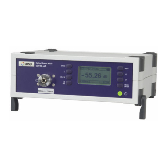
- Page 14 ETTING TARTED Device overview Fig. 1 Frontal view cOPM-A1 JDSU...
- Page 15 Press to: • select relative level power measurement • and hold to set the reference level Press to switch the device on and off. Press to: • scroll up/down in the menus • change values in the menus JDSU cOPM-A1...
-
Page 16: Power Supply
• via the USB control interface Operation from AC power NOTICE: Only the SNT-121A Adapter must be used to operate the cOPM-A1 from AC power. To fit the AC line plug adapter: 1. Select the appropriate AC line plug adapter. - Page 17 (see Fig. Fig. 4 SNT-121A: Changing the AC line plug adapter. To operate the cOPM-A1 from AC power: 1. Connect the SNT-121A DC power cord to the cOPM-A1 DC power socket. (The socket is located on the back panel.) 2. Plug the SNT-121A into the AC line socket.
- Page 18 Although the USB interface is primarily intended for remote control, it can also be used to power the cOPM-A1. To power the cOPM-A1 via the USB interface: ⇒ Just connect a standard USB cable to any USB socket of a PC or USB hub.
-
Page 19: Asic Peration
Display elements Fig. 5 Measurement display External power supply The cOPM-A1 is powered by the external AC adapter when this symbol is shown. Power supply via USB The device is powered via the USB interface for remote operation. -
Page 20: Navigating In The Menus
⇒ Press [MENU ENTER] to open the MAIN menu. The MAIN menu opens. To select a menu item: 1. Press [▲▼] to highlight an item. 2. Press [MENU ENTER] to select the item. To leave a menu without making any changes: ⇒ Press [PREV]. cOPM-A1 JDSU... -
Page 21: Configuring The Device
Select Auto-λ Activate/deactivate “Automatic Wavelength Detection”. Edit Contrast Adjust display contrast. Set Factory Set the device parameters and Default settings to their default values as defined by JDSU. This does not affect any stored measurement results. JDSU cOPM-A1... - Page 22 To edit the λ-Table: 1. Press Edit λ-Table in the CONFIGURATION menu. The EDIT λ-TABLE menu opens (displayed wavelengths may vary according to model and settings). 2. Highlight the entry to be edited and press [MENU ENTER]. A window opens: cOPM-A1 JDSU...
- Page 23 Auto-λ is a special feature developed by JDSU that allows you to identify wavelengths automatically. To do this, the signal is modulated at a certain frequency (by a light source equipped with Auto-λ, such as a JDSU OLS-55/-56), which can be detected by a JDSU cOPM-A1. JDSU cOPM-A1...
- Page 24 Display in Auto-λ mode When Auto-λ mode is activated and different wavelengths are detected, the power levels measured at these wavelengths are displayed simultaneously. Display in Auto-λ mode showing the detected Fig. 6 wavelengths and their power levels. cOPM-A1 JDSU...
- Page 25 The FACTORY DEFAULT menu opens: 2. Press [MENU ENTER] to set the factory defaults. – or – Press any key to exit from the menu without making any changes. Note: Setting the factory default values does not affect your stored measurement results. JDSU cOPM-A1...
- Page 26 1 hour. The device is without any power if • neither the SNT-121A Adapter is connected, • nor a USB connection is established and • no batteries are fitted or the batteries are discharged. cOPM-A1 JDSU...
- Page 27 1. Select Firmware Update in the CONFIGURATION menu. The FIRMWARE UPDATE menu opens: 2. Press [▼] to open the next window. – or – Press [PREV] to cancel. 3. Press [MENU ENTER] to start the update. – or – Press [PREV] to cancel. JDSU cOPM-A1...
- Page 28 (adapter/charger, batteries, USB connection). Selecting a language 1. Select Select Language in the CONFIGURATION menu. The SELECT LANGUAGE menu opens: 2. Press [▲▼] to highlight the language you want and press [MENU ENTER] to select it. cOPM-A1 JDSU...
-
Page 29: Operation
The wavelengths that can be selected by pressing this key are an extract of those contained in the internal wavelength table (λ-Table). Note: See „Editing the Lambda-Table”, page 18 details of how to edit this table. JDSU cOPM-A1... -
Page 30: Displaying Absolute Power Level
Note: The reference level must be stored for each wavelength separately and is saved even when the power is off. Editing the reference level The reference level can be also edited manually. 1. Select Edit Ref. Level in the MAIN menu. cOPM-A1 JDSU... -
Page 31: Displaying Modulated Signals
2. Press [▲▼] to change the value. 3. Press [MENU ENTER] to accept the setting. Displaying modulated signals The cOPM-A1 automatically detects the modulation frequency of light signals modulated at the fixed frequencies of 270 Hz, 1 kHz and 2 kHz.The detected frequency is shown in the lower center display pane. -
Page 32: Emory Anagement
• Measured values stored in pre-defined memory locations. Result memory structure The cOPM-A1 is equipped with a data memory which is structured according to the typical device under test, i.e. a cable made up from several fibers. This hierarchical structure predetermines the memory locations which generally contain the following data: •... -
Page 33: Saving Results Successively
Group 015, Meas 005, these values must be specified in advance (see „Selecting the store location”, page 32). If you attempt to store data at memory locations that are already occupied by the results of previous measurements, a warning will be displayed: JDSU cOPM-A1... -
Page 34: Displaying Stored Results
The last results stored are displayed. Stored results example: Group 025, Meas 004: 3 wavelengths detected, relative measurement mode with measured levels and reference values. To select another Measurement in the current Group: ⇒ Press [▲▼] to increase/decrease the Meas #. cOPM-A1 JDSU... - Page 35 The current Group and Meas 001 will be displayed: 3. Press [▲▼] to increase/decrease the Group #. 4. Press [MENU ENTER]. MEAS # will be highlighted. 5. Press [▲▼] to increase/decrease the Meas #. ⇒ Press [MENU ENTER] to exit from the menu. JDSU cOPM-A1...
-
Page 36: Selecting The Store Location
6. Press [▲▼] to edit the Group #. 7. Press [MENU ENTER]. Meas # is highlighted. 8. Press [▲▼] to edit the Meas #. 9. Press [PREV] to exit from the menu. ⇒ Press [Store] to store the results. cOPM-A1 JDSU... -
Page 37: Clearing The Memory
EMORY ANAGEMENT Clearing the memory You can store up to 350 data sets in the cOPM-A1. Each data set can contain up to 3 measurements in Auto λ mode (in conjunction with a JDSU OLS-55 light source). Each data set contains the wavelength, the relative power level and reference value or the absolute power level, and the date / time when it was stored. - Page 38 1. Press [▲▼] to select Clear All. 2. Press [MENU ENTER] to clear all memory data. 3. Press [PREV] to exit the menu. Note: If you now store results, they will be stored at memory location Group 001 and Meas 001. cOPM-A1 JDSU...
-
Page 39: Maintenance
3. Wipe off the plug end surface using cleaning sticks soaked in isopropanol. This cleaning method is very effective and leaves no residues. 4. Blow out the test adapter with clean compressed air (available in spray cans, e.g. Anti Dust Spray). JDSU cOPM-A1... -
Page 40: Cleaning The Instrument
Water and cleaning fluids The device may be damaged or destroyed if water or cleaning fluids CAUTION get inside it. Make sure that water or cleaning fluids do not get inside the instrument. cOPM-A1 JDSU... -
Page 41: Remote Control
EMOTE ONTROL Communication interface The cOPM-A1 is equipped with a USB interface for remote control via a PC. The driver files needed on the PC for this can be download from www.jdsu.com/ test_and_measurement. The following table lists the parameter types used in remote control. -
Page 42: Commands
(not alphabetically). This sort order reflects a fairly standard application of the device. Overview Utility commands *IDN? *OPC? :SYST:PERM:POW :DISP:CONT :DISP:CONT? :SYST:LANG :SYST:LANG? :SYST:DATE :SYST:DATE? :SYST:TIME :SYST:TIME? Power Metercommands :SYST:CAL:WAV:MAX? :SYST:CAL:WAV:MIN? :SYST:CAL:WAV:TAB :SYST:CAL:WAV:TAB? :SYST:CAL:WAV :SYST:CAL:WAV? :DISP:UNIT :DISP:UNIT? :REF:STAT :REF:STAT? :REF:VAL :REF:VAL? :WAV:AUTO cOPM-A1 JDSU... - Page 43 Unit / Info *IDN? Returns the unique identification of the device. Response type: <STRING_RESPONSE_DATA> e.g. JDSU Germany GmbH, cOPM-A1/01,A-0106,V03.30 *OPC? Returns “1” as soon as all operations in progress have been completed. :SYST Ensures the device is switched on :PERM permanently i.e.
- Page 44 • FR: French :SYST Returns the current language. :LANG? EN or DE or FR :SYST Sets the date (yy,mm,dd). :DATE e.g. :SYST:DATE 07,11,30 :SYST Returns the date (yy,mm,dd). :DATE? e.g. 07,11,30 :SYST Sets the time (hh,mm,ss). :TIME e.g. :SYST:TIME 23,59,59 cOPM-A1 JDSU...
- Page 45 :SYST:CAL:WAV:TAB 820,850, 980,1280,1300,1310,1480,1510, 1550,1625 Returns the contents of the λ-Table. :SYST :CAL Response type: <NR1,NR1,...> :WAV :TAB? :SYST Selects the calibration wavelength from the λ-Table. :CAL :WAV See :SYST:CAL:WAV:TAB? for more details. Parameter type: <NR1> e.g. :SYST:CAL:WAV 1310 JDSU cOPM-A1...
- Page 46 • 1: relative value :REF Sets the value for the specified :VAL wavelength (to which the power level reading is referred) in relative mode. Parameter type: <NR1>,<NRf> e.g. :REF:VAL 1310,-34.50 sets the reference value for 1310 nm to -34.50 dBm. cOPM-A1 JDSU...
- Page 47 :FREQ? incoming signal. • “0” otherwise :FETC Returns • “0”, if the incoming signal is not :INT modulated or Auto-λ modulation :FREQ? frequency is detected. • the modulation frequency [Hz] otherwise Response type: <NR1> JDSU cOPM-A1...
- Page 48 Returns number of measurements :USED? stored. :MEM Selects the group (1...350) where the :GROU measurement is stored, deleted or recalled. Parameter type: <NR1> e.g. :MEM:GROU 10 :MEM Returns the group where the :GROU? measurement is stored, deleted or recalled. e.g. 10 cOPM-A1 JDSU...
- Page 49 Stores the current measurement :STOR under the current measurement :MEAS group and number. Note: If this command is repeated immediately (i.e. with no other commands, such as :MEM:REC:MEAS? in between), the identifier increments by 1 for the next store operation. JDSU cOPM-A1...
- Page 50 :ALL? Format for each measurement: see :MEM:REC:MEAS? :MEM Deletes the current measurement. :DEL :MEAS :MEM Deletes all measurements in the :DEL specified group (1...350). :GROU e.g. :MEM:DEL:GROU 20 :MEM Deletes all measurement results from :DEL the memory. :ALL cOPM-A1 JDSU...
-
Page 51: Specifications
75% RH, 9 to 50 µm Display Display type Graphical display, 64 x 128 pixels, monochrome, Memory Memory capacity 1000 measurement results, 350 data sets Data readout / remote via USB interface (INF file control for Windows XP included) JDSU cOPM-A1... - Page 52 1) When connected to the AC power plug Ambient temperature Nominal range of use -10 to +55 °C Air humidity Humidity Non-condensing Dimensions and weight Dimensions (w x h x d) 250 x 88 x 210 mm Weight 1.6 kg cOPM-A1 JDSU...
-
Page 53: Integrating Sphere Specifications
Nominal line voltage range 100 to 240 VAC Nominal line frequency range 47 to 63 Hz Power consumption max. 8.5 W Output 12 V / 1.25 A Temperature range 0 to +40°C Condensation – even occasional – is not tolerable. JDSU cOPM-A1... -
Page 54: Ordering Information
RDERING NFORMATION cOPM-A1, Power meter with InGaAs BN 2297/02 Diode Calibration report BN 2297/90.01 Accessories 2 mm InGaAs MAP Power Meter AC101 FC detector adapter 2297/00.01 AC103 SC detector adapter 2297/00.03 On Request AC100 AC100 Detector cap AC102 ST detector adapter... -
Page 55: Index
NDEX NDEX AC line plug adapter 12 Maintenance 35 Accessories 50 Memory Management 28 Auto-Lambda mode 19 Memory position 32 Auto-Zeroing 26 Memory structure 28 Menu Configuration 17 Cleaning Menu navigation 16 optical connections 35 Modulated signal, displaying the instrument 36 the test port 35 Clearing the memory 33 Common features 1... - Page 56 NDEX Time 22 Updating the firmware 23 Wavelength, selecting a 25 oOPM-A1 JDSU...
- Page 57 JDSU Environmental Management Program Superb performance and high quality have always characterized JDSU datacom and telecom measurement technology products. In this same world-class tradition, JDSU has an established, proactive program of environmental management. Environmental management is an integral part of JDSU’s business philosophy and strategy requiring the development of long-term, productive solutions to problems in the key areas of economics, technology, and ecology.
- Page 58 Environmental management partnerships JDSU encourages our customers and suppliers who take this responsibility seriously to join JDSU in establishing their own environmental management programs. Recycling used products This product complies with the European Union Waste Electrical and Electronic Equipment directive (WEEE), 2002/96/EC. This product should not be disposed of as unsorted municipal waste and should be collected separately and disposed according to your national regulations.