Table of Contents
Advertisement
Quick Links
Instruction Manual
D450319T012
September 2016
Type 63EGLP Relief Valve
WaRninG
!
Failure to follow these instructions or
to properly install and maintain this
equipment could result in an explosion
and/or fire causing property damage and
personal injury or death.
Fisher™ relief valves must be
installed, operated and maintained
in accordance with federal, state and
local codes, rules and regulations
and Emerson Process Management
Regulator Technologies, inc.
(Emerson) instructions.
if a leak develops or if the outlet
continually vents process fluid, service
to the unit may be required. Failure
to correct trouble could result in a
hazardous condition. Call a gas service
person to service the unit. Only a
qualified person shall install or service
the unit.
introduction
Scope of the Manual
This instruction manual provides instructions for
the installation, maintenance and parts ordering
information for a Type 63EGLP relief valve with a
Type 6358EBLP or 6358EBHLP pilot.
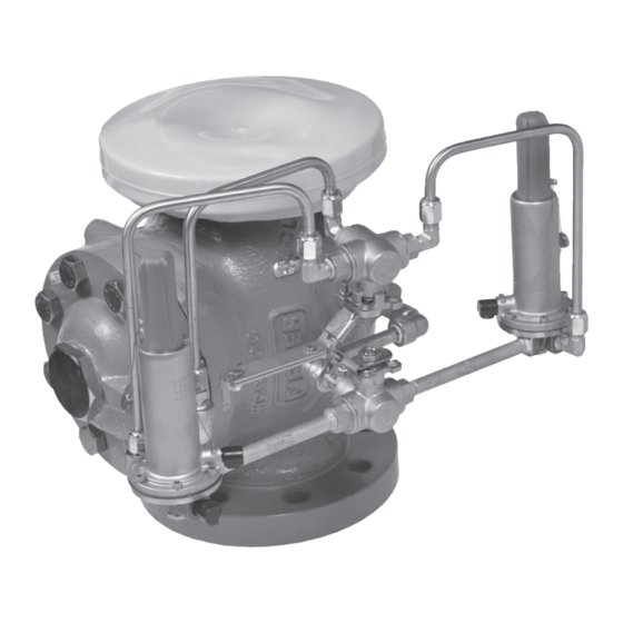
Type 63EGLP
P1673_1
Figure 1. Type 63EGLP Bulk Plant Relief Valve
6358EBLP_1
Figure 2. Type 6358EBLP Pilot
Advertisement
Table of Contents

Related Manuals for Emerson Fisher 63EGLP Series


Summary of Contents for Emerson Fisher 63EGLP Series
- Page 1 Fisher™ relief valves must be installed, operated and maintained in accordance with federal, state and local codes, rules and regulations and Emerson Process Management Regulator Technologies, inc. P1673_1 (Emerson) instructions. if a leak develops or if the outlet Figure 1.
-
Page 2: Specifications
Type 63EGLP Specifications Specifications for the Type 63EGLP construction is listed on Specifications section and Tables 1 to 3. The specifications for a given construction as it originally comes from the factory are stamped on nameplates located on the main valve body. The pilot set pressure appears on the pilot spring case. available Constructions Main Valve Port Diameter: Type 63EGLP with two Type 6358EBLP Pilots... - Page 3 Type 63EGLP Table 1. 63EGLP Series Bulk Plant Relief Valves Flow Rate FLOW RaTE, REPLaCEMEnT SET PRESSuRE SCFM / SCMM OF aiR TyPE nuMBER COnTainER COnnECTiOn PiLOT TyPE nuMBER psig Per uL -132 PED Category iV ® 63EGLP-250 17.2 6358EBLP-250 38,794 / 1099 63EGLP-EB1 85 to 140...
- Page 4 Type 63EGLP aCTiVE aCTiVE inaCTiVE PiLOT PiLOT inaCTiVE PiLOT PiLOT SPRinG VaLVE DiaPHRaGM HanDLE aSSEMBLy HanDLE aSSEMBLy PiLOT DiSCHaRGE Main VaLVE DiSCHaRGE Main SPRinG VaLVE PLuG BULK STORAGE TANK BULK STORAGE TANK TyPE 63EGLP aT nORMaL COnDiTiOn TyPE 63EGLP aT OVERPRESSuRE COnDiTiOn (BOTH Main VaLVE anD aCTiVE PiLOT aRE CLOSED) (aCTiVE PiLOT DiSCHaRGES LOaDinG PRESSuRE, Main VaLVE DiSCHaRGES ExCESS inLET PRESSuRE)
-
Page 5: Principle Of Operation
Type 63EGLP HOLLOW PaSSaGE in VaLVE PLuG STEM DiaPHRaGM aSSEMBLy uPPER PORTiOn OF VaLVE PLuG FixED RESTRiCTiOn LOWER PORTiOn TO Main VaLVE OF VaLVE PLuG DiaPHRaGM TO ExHauST PORT ExPanDED ViEW OF THE TyPE 6358EBLP RELiEF PiLOT DiaPHRaGM aSSEMBLy anD VaLVE PLuG inLET PRESSuRE OuTLET (ExHauST) PRESSuRE aTMOSPHERiC PRESSuRE... - Page 6 Type 63EGLP PORT a (ExHauST) PORT C (LOaDinG) PORT D (COnTROL) PORT a (ExHauST)—THE Main VaLVE LOaDinG PRESSuRE iS DiSCHaRGED TO THE Main VaLVE OuTLET OR TO aTMOSPHERE PRESSuRE. PORT C (LOaDinG)—a LOaDinG PRESSuRE SiGnaL iS SEnT FROM THiS PORT TO THE Main VaLVE DiaPHRaGM CaSinG. PORT D (COnTROL)—THE Main VaLVE inLET PRESSuRE iS SEnSED aT THiS PORT.
-
Page 7: Startup And Adjustment
5. Apply wire seal or other adjustment protection if available. Due to the care Emerson takes in meeting all manufacturing requirements (heat treating, Shutdown dimensional tolerances, etc.), use only replacement parts manufactured or furnished by Emerson. - Page 8 Type 63EGLP CauTiOn WaRninG To avoid personal injury and a small amount of vapor release equipment damage, isolate the valve may occur during steps 2 through 4. from all pressure. Cautiously release if the main valve or alternate pilot pressure from the valve before continuously vents while conducting attempting disassembly.
- Page 9 Type 63EGLP 7. Clean the exposed pipe nipple and apply new 1. The Type 6358EBLP pilot ships preassembled thread sealant before threading the new pilot onto with a 1/4 in.-by-Compression elbow (key 43, the nipple. Make sure the pipe wrench is utilized Figure 9) in Port C oriented in the same direction to secure the pipe nipple.
- Page 10 Type 63EGLP 7. Apply thread sealant to exposed end of the off trapped pressure. After purging the inactive 6 in. Male NPT pipe nipple. To install the new pilot, pilot, finger tighten the compression fitting, then thread pilot Port D onto the pipe nipple until snug, use appropriate wrench to turn the nuts to 1/4 turn.
-
Page 11: Parts Ordering
Type 63EGLP W2772_1 W3012_1 FLiPPinG THE BODy FLanGE OVER anD unSCREWinG OF CaGE FROM LiFTinG THE EnTiRE TRiM PaCKaGE anCHORinG iT On THE VaLVE BODy BODy FLanGE Figure 6. Replacing Trim Parts on Site Using Body as Holding Fixture note be wrapped around the cage or a soft bar may be inserted through the windows of a standard cage. -
Page 12: Parts List
Type 63EGLP Parts List Types 6358EBLP and 6358EBHLP Pilot (Figure 8) Main Valve (Figure 7) Description Part number Pilot Body, CF8M Stainless steel 39A5972x012 Description Part number Spring Case, Stainless steel 27B9722x012 Main Valve Parts kit (included are keys 4, 12, Body Plug, Stainless steel 1B7975x0052 14, 15, 17, 20 and 21) - Page 13 Type 63EGLP 35A3174-A COMPLETE STEEL Main VaLVE aSSEMBLy 25A3169_B TRiM PaCKaGE aSSEMBLy Figure 7. Type 63EGLP Main Valve Trim Package...
- Page 14 Type 63EGLP 48B3430 48B3431_A TyPE 6358EBLP PiLOT inTERiOR ViEW TyPE 6358EBHLP PiLOT inTERiOR ViEW 48B3430_A TyPE 6358EBLP PiLOT WiTH DiaPHRaGM LiMiTER FOR 180 TO 350 psig / 12.4 TO 24.1 bar SET PRESSuRE RanGE inTERiOR ViEW aPPLy SEaLanT (S) Figure 8. Types 6358EBLP and 6358EBHLP Pilot Assemblies...
-
Page 15: Front View
Type 63EGLP TYPE 6358EBLP PILOT ASSEMBLY TYPE 6358EBLP PILOT ASSEMBLY FRONT VIEW ERAA03024 BACK VIEW (ALL PARTS EXCEPT PILOTS FROM TYPE 63EGX7) Figure 9. Mounting Parts Assembly... - Page 16 D450319T012 © 2013, 2016 Emerson Process Management Regulator Technologies, Inc. All rights reserved. 09/16. Emerson Process Management The Emerson logo is a trademark and service mark of Emerson Regulator Technologies Electric Co. All other marks are the property of their prospective owners.