Table of Contents
Advertisement
Quick Links
Instruction Manual
D100248X012
February 2020
Types 66R and 66RR Relief Valves
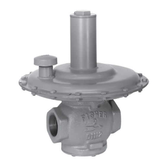
W1935
TYPE 66R RELIEF VALVE
Introduction
Scope of the Manual
This manual describes and provides instructions, installation,
and parts list for Type 66R direct-operated relief valve* and
for Type 66RR pilot-operated relief valve* complete with
Type T208RR pilot. Instructions and parts list for other
Fisher™ equipment used with these relief valves are found
in separate manuals.
Product Description
Types 66R and 66RR throttling relief valves (Figure 1) are
used to help protect a system against overpressure, or to
maintain an inlet or backpressure. The Type 66R direct-
operated construction is used for set pressure ranges of
2 in. w.c. to 5 psig / 5 mbar to 0.34 bar, while the Type 66RR
pilot-operated construction with the Type T208RR pilot is used
for set pressure ranges of 4 in. w.c. to 7 psig / 10 mbar to
0.48 bar.
*Relief valve defined in ANSI standard B95.1-1972. Not all codes or regulations permit these valves to be used as final overpressure protection devices.
Figure 1. Typical Constructions
Principle of Operation
Type 66R Relief Valve
Refer to Figure 2. Inlet pressure registers under the diaphragm
and is opposed by the spring. When the inlet pressure
increases above the spring setting, the valve plug opens in
a throttling manner and relieves the inlet pressure. As inlet
pressure drops back to set pressure, the spring closes the
valve plug.
Type 66RR Relief Valve
Refer to Figure 2. Inlet pressure registers on the bottom
of the pilot diaphragm through the upstream control line
and bleeds through a fixed restriction in the pilot to provide
loading pressure that helps the main valve spring keep the
main valve plug tightly shut off. When inlet pressure exceeds
the setting of the pilot spring, the pilot diaphragm moves
upward, opening the pilot valve disk and relieving some of
the pressure from the top of the main valve diaphragm. At
the same time, the inlet pressure increase registers on the
bottom of the main valve diaphragm.
Types 66R and 66RR
W1908
TYPE 66RR RELIEF VALVE
Advertisement
Table of Contents

Related Manuals for Emerson FISHER 66R


Summary of Contents for Emerson FISHER 66R
- Page 1 Instruction Manual Types 66R and 66RR D100248X012 February 2020 Types 66R and 66RR Relief Valves W1908 W1935 TYPE 66R RELIEF VALVE TYPE 66RR RELIEF VALVE Figure 1. Typical Constructions Introduction Principle of Operation Scope of the Manual Type 66R Relief Valve This manual describes and provides instructions, installation, Refer to Figure 2.
-
Page 2: Specifications
Types 66R and 66RR Specifications Refer to Specifications for Types 66R and 66RR constructions listed on page 2. Some specifications for a given relief valve as it originally comes from the factory are stamped on nameplates located on the Type 66R relief valve body or Type 66RR main valve body. - Page 3 Types 66R and 66RR PILOT CONTROL FIXED SPRING RESTRICTION PILOT VALVE DISK DIAPHRAGM TYPE T208RR MAIN VALVE PILOT DIAPHRAGM VALVE STEM VALVE M1041 PLUG SKIRT VALVE PLUG SKIRT INLET PRESSURE OUTLET PRESSURE MAIN VALVE ATMOSPHERIC PRESSURE LOADING PRESSURE TYPE 66R TYPE 66RR Figure 2.
- Page 4 Types 66R and 66RR 8. Each unit is factory-set for the set pressure specified CONTROL LINE on the order. If no setting is specified, set pressure is factory set at the mid-range of the Type 66R spring GAS TO (key 6, Figure 6) or the Type 66RR pilot control spring FUEL (key 6, Figure 8).
-
Page 5: Maintenance
Types 66R and 66RR Maintenance 5. Remove the spring seat washer (key 36) if used, lower spring seat (key 17), stiffener plate (key 39) if used, Relief valve parts are subject to normal wear and must upper diaphragm plate (key 4), diaphragm (key 5), be inspected and replaced as necessary. - Page 6 Types 66R and 66RR 7. Secure the diaphragm case with the washers (key 34) 16. Complete the relief valve adjustment according to the and cap screws (key 20), tightening the cap screws with “Startup” section. an even crisscross pattern. With a high-temperature Fluorocarbon (FKM) diaphragm, use a new case Type 66RR Relief Valve Pilot gasket (key 66, not shown), and install it on top of the...
-
Page 7: Parts Ordering
Types 66R and 66RR 2. Remove the adjusting screw (key 35) and change the 4. To replace the lever assembly (key 16), remove the control spring (key 6) to match the desired spring range. machine screws (key 17). To replace the stem (key 14) or stem seal O-ring (key 30), also perform Body Area 3. -
Page 8: Parts List
Types 66R and 66RR Parts List Description Part Number O-ring Type 66R Relief Valve (Figure 6) or Nitrile (NBR) NPS 2 / DN 50 body 1D785306992 Type 66RR Main Valve Body (Figure 7) NPS 3 / DN 80 body 1D785406992 NPS 4 / DN 100 body 1D785506992 Description... - Page 9 Types 66R and 66RR Description Part Number Description Part Number Lower Diaphragm Plate, Zinc-plated steel Closing Cap (1 required without and 3 required with Type 66R thru 3 psig / 0.21 bar sealing diaphragm) set pressures and all Type 66RR, Die-cast zinc 1A589544022 NPS 2 / DN 50 body 1D475725062...
- Page 10 Types 66R and 66RR Key 2, Spring Case Assembly Key 6, Spring BODY SIZE, SPRING CASE ASSEMBLY CONSTRUCTION RELIEF SET PRESSURE RANGE SPRING PART NUMBER NPS / DN PART NUMBER Type 66R 2 to 8 in. w.c. / 5 to 20 mbar 1D7614X0012 1D765427012 Type 66RR...
- Page 11 Types 66R and 66RR 40A6361-B DETAIL OF OPTIONAL CAST IRON CONTRUCTION WITH SEALING DIAPHRAGM AND TAPPED DIAPHRAGM CASE 30A6359-B B1433 CLOSING CAP AND ADJUSTING SCREW DETAIL FOR 3 TO 5 psig / 0.21 to 0.34 bar CONSTRUCTION COMPLETE STANDARD ASSEMBLY WITH INTERNAL REGISTRATION Figure 6.
- Page 12 Technologies, Inc. All rights reserved. 02/20. Emerson Automation Solutions The Emerson logo is a trademark and service mark of Emerson Electric Co. All other marks are the property of their prospective owners. Fisher™ is a mark owned by Fisher Controls International LLC, a...