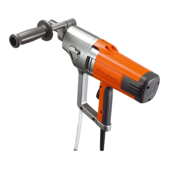
Husqvarna DM 230 Workshop Manual
Hide thumbs
Also See for DM 230:
- Operator's manual (100 pages) ,
- Safety instructions (4 pages) ,
- Price list (48 pages)
Table of Contents
Advertisement
Advertisement
Table of Contents

Related Manuals for Husqvarna DM 230


Summary of Contents for Husqvarna DM 230
- Page 1 Workshop manual DM 230 HUSQVARNA CONSTRUCTION PRODUCTS...
-
Page 2: Table Of Contents
CONTENTS Page HUSQVARNA LITERATURE 2. COMPONENTS, WORK TIPS DM 230 SPECIAL FUNCTION COMPONENTS 4. DISMANTLING IN BASIC MODULES 5. GEAR HOUSING – INTERMEDIATE SHAFT 6. GEAR HOUSING – SPINDLE SHAFT 7. GEAR HOUSING – BEARING REPLACEMENT 8. CARBON BRUSHES 9. CIRCUIT BOARD 10. - Page 3 LITERATURE Workshop manual The workshop manual covers virtually all work in the workshop that involves the DM 230. Some very simple and rather obvious repair work has been omitted. Disposition The initial section with the titles “Special function components” and “Dismantling in basic modules”...
-
Page 4: Components, Work Tips
COMPONENTS, WORK TIPS Components 1. Drill spindle 2. Gear knob 3. Gear housing 4. Gear box cover 5. Leakage duct (fault indicator) 6. Spirit level 7. Electric motor 8. Inspection cover to carbon brushes 9. SmartStart™ 10. Power switch lock 11. -
Page 5: Special Function Components
SPECIAL FUNCTION COMPONENTS Basic modules The machine can be separated into three basic modules: 1. The gear housing with three gear selection positions. 2. The gear box cover that separates the oil-filled gear housing from the opposite side where the water to the drill spindle is supplied. -
Page 6: Dismantling In Basic Modules
DISMANTLING IN BASIC MODULES Gear housing/electric motor Virtually all service work requires the separation of the gear housing from the electric motor. Oil change Oil changes are made through the hole in the electric motor's drive shaft in the gear box cover. Separation Separation Motor/gear housing... - Page 7 DISMANTLING IN BASIC MODULES Separation Separation Gear box cover/gear Gear box cover/gear housing housing 1. Remove the two screws. 1. Remove the two screws. 2. Pull off the gear box cover from the 2. Pull off the gear box cover. gear housing.
-
Page 8: Gear Housing - Intermediate Shaft
GEAR HOUSING – INTERMEDIATE SHAFT Function The gear housing contains a transmission that reduces the high speed of the electric motor to a lower speed on the spindle shaft. The transmission has been constructed on two shafts: intermediate shaft (A) and spindle shaft (B). The electric motor powers the top gear wheel on the intermediate shaft. - Page 9 GEAR HOUSING – INTERMEDIATE SHAFT Spring washers The spring washers provide the brake force to the slip clutch when the nut has been fitted and tightened with the correct torque. It is particularly important for this function that the washers are correctly turned and that they are intact.
-
Page 10: Gear Housing - Spindle Shaft
GEAR HOUSING – SPINDLE SHAFT Spindle shaft The spindle shaft is powered by the intermediate shaft which in turn is powered by the electric motor. The complete spindle shaft contains a number of moving parts, including axially moving gear wheel for gear function. The transmission in this machine is rarely the cause of any problems. - Page 11 GEAR HOUSING – SPINDLE SHAFT Remove the wedge. In order to remove the lock ring, you need small lock ring pliers of make: Milbar/Imperial IR-15R or equivalent. Start by turning the lock ring to ensure the opening is accessible by pliers in the gear wheel.
-
Page 12: Gear Housing - Bearing Replacement
GEAR HOUSING – BEARING REPLACEMENT Bearings The lower bearing of the spindle shaft is forced fitted to the gear housing and on the shaft. Circlips on the shaft secure the position. It is easiest and best to replace the bearing using a hydraulic press. If this is unavailable, you can remove and fit with a low force fit by utilising differences in temperature. - Page 13 GEAR HOUSING – BEARING REPLACEMENT Tools Dismantling The following tools are required for dismantling the gear housing's bearing: 1. Internal bearing extractor to grip behind the bearings. 2. Use a counter stay device where there is a dolly. 3. A slide hammer is an alternative to the counter stay device if there is no dolly available.
-
Page 14: Carbon Brushes
CARBON BRUSHES Replacing the carbon brushes The two carbon brushes transfer electric current to the motor's rotor. A cable from the stator is connected to the screw in the holder. The carbon brush cable is connected to the same screw. The carbon brushes are wear parts that must be checked regularly. -
Page 15: Circuit Board
CIRCUIT BOARD Circuit board The circuit board at the rear of the motor controls the motor's functions. Ensure the cable runs and connections are correct when reassembling: 1. Green cable – connects to earth point in the handle. 2. Grey cable – connects to stator winding. 3. -
Page 16: Rotor
ROTOR Functional test Preparations Remove the inspection cover to the carbon brushes. Remove the screw to the circuit board and fold this to the side to enable you to rotate the motor with a screwdriver. Remove the screws for the cable attachment to the carbon brushes. Put the cable connections to the stator to one side ensuring these have no contact. - Page 17 Start by fitting the bearing in the bearing the bearing holder. holder. Select a tool that covers the outer ball race e.g. Husqvarna 502 50 82-01 Fit the bearing unit on the (intended for the oil seals in power rotor shaft. Use a tool that cutters).
-
Page 18: Stator
STATOR Functional test Breaks in the stator winding are easily identified by carrying out the functional test described below. In general, short-circuited windings can also be identified, particularly if the short circuit excludes current in several winding turns. If the short circuit only excludes a few turns, the measurement is unlikely to record this. -
Page 19: Tools
TOOLS ● = Service operation The tools listed below are available from Husqvarna. The special tools below are needed for service work to DM 230 but are not sold by Husqvarna. 510 22 11-01 Lock ring pliers Special socket Make: Milbar/Imperial IR-15R. - Page 20 www.husqvarnacp.com 115 13 18-26 English 2008-11...