Table of Contents
Troubleshooting

Related Manuals for NETGEAR MS510TXM


Summary of Contents for NETGEAR MS510TXM
- Page 1 Hardware Installation Guide 8-Port Multi-Gigabit/10G Ethernet (Ultra60 PoE++) Smart Managed Pro Switch with 2 SFP+ Ports Models MS510TXM MS510TXUP NETGEAR, Inc. January 2021 350 E. Plumeria Drive 202-12153-01 San Jose, CA 95134, USA...
- Page 2 See the regulatory compliance document before connecting the power supply. For NETGEAR’s Privacy Policy, visit https://www.netgear.com/about/privacy-policy. By using this device, you are agreeing to NETGEAR’s Terms and Conditions at https://www.netgear.com/about/terms-and-conditions. If you do not agree, return the device to your place of purchase within your return period.
-
Page 3: Table Of Contents
Contents Chapter 1 Introduction Overview....................6 Features....................6 Safety instructions and warnings............8 Chapter 2 Hardware Overview Hardware overview of model MS510TXM........12 Front panel model MS510TXM............12 LEDs model MS510TXM...............13 Back panel model MS510TXM.............13 Hardware overview of model MS510TXUP........14 Front panel model MS510TXUP..........14 LEDs model MS510TXUP..............15 Back panel model MS510TXUP...........16... - Page 4 8-Port Multi-Gigabit/10G Ethernet (Ultra60 PoE++) Smart Managed Pro Switch with 2 SFP+ Ports Step 8: Apply power and check the LEDs........31 Step 9: Manage the switch..............32 Chapter 5 Troubleshooting Troubleshooting chart...............36 PoE troubleshooting suggestions............37 Additional troubleshooting suggestions.........38...
-
Page 5: Chapter 1 Introduction
This hardware installation guide complements the installation guide that came with your switch and applies to the following NETGEAR switch models: • MS510TXM: 8-Port Multi-Gigabit/10G Ethernet Smart Managed Pro Switch with 2 SFP+ Ports • MS510TXUP: 8-Port Multi-Gigabit/10G Ethernet Ultra60 PoE++ Smart Managed... -
Page 6: Overview
8-Port Multi-Gigabit/10G Ethernet (Ultra60 PoE++) Smart Managed Pro Switch with 2 SFP+ Ports Overview The switch provides eight Gigabit Ethernet multispeed copper ports and two dedicated SFP+ fiber uplink ports that support 10G and 1G. Four of the multispeed copper ports support both 1G and 2.5G and each of the other four multispeed copper ports supports 1G, 2.5G, 5G, and 10G. - Page 7 • Two fans for model MS510TXM and three fans for model MS510TXUP with variable-speeds that can lower the noise level during low temperatures. • Acoustic noise at 25°C is equal to or less than 25 dBA for model MS510TXM and 33 dBA for model MS510TXUP.
-
Page 8: Safety Instructions And Warnings
Before connecting the product to outdoor cables or devices, see https://kb.netgear.com/000057103 for additional safety and warranty information. Failure to follow these guidelines can result in damage to your NETGEAR product, which might not be covered by NETGEAR’s warranty, to the extent permissible by applicable law. - Page 9 8-Port Multi-Gigabit/10G Ethernet (Ultra60 PoE++) Smart Managed Pro Switch with 2 SFP+ Ports We recommend that only a trained technician services components inside these compartments. • If any of the following conditions occur, unplug the product from the power outlet, and then replace the part or contact your trained service provider: Depending on your product, the power adapter, power adapter cable, power cable, extension cable, or plug is damaged.
- Page 10 8-Port Multi-Gigabit/10G Ethernet (Ultra60 PoE++) Smart Managed Pro Switch with 2 SFP+ Ports If your product uses a power adapter: If you were not provided with a power adapter, contact your local NETGEAR reseller. The power adapter must be rated for the product and for the voltage and current marked on the product electrical ratings label.
-
Page 11: Chapter 2 Hardware Overview
Hardware Overview This chapter describes the switch hardware features. The chapter includes the following sections: • Hardware overview of model MS510TXM • Hardware overview of model MS510TXUP • Switch hardware interfaces... -
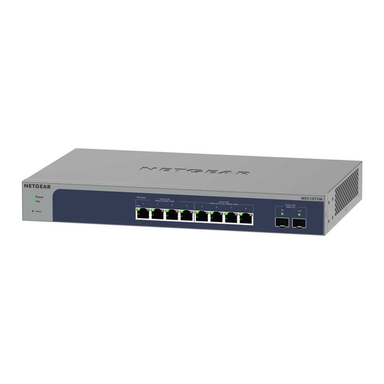
Page 12: Hardware Overview Of Model Ms510Txm
Description System LEDs Power LED and Fan LED. For more information about the LEDs, see LEDs model MS510TXM on page 13. Reset button Recessed multi-function Reset button (see Multi-function Reset button on page 18). Ports 1, 2, 3, and 4 Four independent 2.5GBASE-T RJ-45 ports that also support 100/1000BASE-T. -
Page 13: Leds Model Ms510Txm
Solid green: The switch is powered on and operating normally. If you changed the management mode of the switch to NETGEAR Insight, the switch is not yet added to an Insight managed network or not yet connected to the Insight cloud management server. -
Page 14: Hardware Overview Of Model Ms510Txup
8-Port Multi-Gigabit/10G Ethernet (Ultra60 PoE++) Smart Managed Pro Switch with 2 SFP+ Ports Figure 2. Back panel model MS510TXM Hardware overview of model MS510TXUP Model GS510TXUP provides eight Gigabit Ethernet Ultra60 PoE++ (802.3bt) multispeed copper ports and two dedicated SFP+ fiber uplink ports that support 10G and 1G. Four of the multispeed copper ports support 2.5G, 1G, and 100M and each of the other four... -
Page 15: Leds Model Ms510Txup
Solid green: The switch is powered on and operating normally. If you changed the management mode of the switch to NETGEAR Insight, the switch is not yet added to an Insight managed network or not yet connected to the Insight cloud management server. -
Page 16: Back Panel Model Ms510Txup
8-Port Multi-Gigabit/10G Ethernet (Ultra60 PoE++) Smart Managed Pro Switch with 2 SFP+ Ports Table 4. LEDs on the front panel of model MS510TXUP (Continued) Description Ports 1–4, left LEDs Off: No link is established. Link, speed, and Solid green: A valid link at a speed of 2.5 Gbps is established. activity Blinking green: The port is transmitting or receiving packets at 2.5 Gbps. -
Page 17: Switch Hardware Interfaces
8-Port Multi-Gigabit/10G Ethernet (Ultra60 PoE++) Smart Managed Pro Switch with 2 SFP+ Ports Switch hardware interfaces The following sections describe the hardware interfaces on the switch. RJ-45 ports for 100/1000M and 2.5G/5G/10G BASE-T Ethernet connectivity All RJ-45 copper ports support autosensing. When you insert a cable into an RJ-45 port, the switch automatically ascertains the maximum speed. -
Page 18: Transceiver Modules And Cables For Sfp+ Fiber Ports
(SFP) gigabit interface converters (GBICs, also referred to as transceiver modules) and direct attach cables (DACs) for fiber connectivity. GBICs and DACs are sold separately from the switch. The switch supports the following NETGEAR SFP and SFP+ transceiver modules and cables: • Short-reach fiber transceiver modules: AGM731F: SFP transceiver 1000BASE-SX, SFP multimode LC GBIC •... -
Page 19: Poe Port Capacities And Budget For Model Ms510Txup
• Reset the switch to factory default settings and reset the registration status: This option can be useful if you want to register the switch under a different name or account. This option requires you to first contact NETGEAR support at netgear.com/support so that the NETGEAR registration status on the NETGEAR server can be reset. - Page 20 328 feet (100 meters). If a powered device (PD) receives insufficient PoE power from the switch, consider using a shorter cable. For more information about PoE, see the user manual, which you can download by visiting netgear.com/support/download. Hardware Overview Hardware Installation Guide...
-
Page 21: Chapter 3 Applications
Applications The switch is designed to provide flexibility in configuring multispeed network connections. This chapter shows application examples with 10G, 5G, 2.5G, and 1G connections and, for model MS510TXUP, multispeed PoE++ connections. The chapter includes the following sections: • Multispeed PoE++ and PoE+ access points and cameras •... -
Page 22: Multispeed Poe++ And Poe+ Access Points And Cameras
8-Port Multi-Gigabit/10G Ethernet (Ultra60 PoE++) Smart Managed Pro Switch with 2 SFP+ Ports Multispeed PoE++ and PoE+ access points and cameras Model MS510TXUP supports 8 PoE++ ports. The switch can supply up to 60W PoE++ (802.3bt) to each port up to its total maximum PoE power budget of 295W across all active PoE++ ports. -
Page 23: Multispeed Backbone Switching
8-Port Multi-Gigabit/10G Ethernet (Ultra60 PoE++) Smart Managed Pro Switch with 2 SFP+ Ports If the power requirements for attached devices exceed the total power budget of the switch, the PoE power to the device on the highest-numbered active PoE port is disabled to make sure that the devices connected to the higher-priority, lower-numbered PoE ports are supported first. -
Page 24: 10G Network Storage And Redundancy
8-Port Multi-Gigabit/10G Ethernet (Ultra60 PoE++) Smart Managed Pro Switch with 2 SFP+ Ports 10G network storage and redundancy You can use two switches in a data redundancy configuration to provide 10G redundant connections for 10G storage platforms and 10G servers. Each system consists of one switch, one server, and one storage platform. -
Page 25: Chapter 4 Installation
Installation This chapter describes the installation procedures for the switch. Switch installation involves the steps described in the following sections: • Step 1: Prepare the site • Step 2: Protect against electrostatic discharge • Step 3: Unpack the switch • Step 4: Install the switch •... -
Page 26: Step 1: Prepare The Site
8-Port Multi-Gigabit/10G Ethernet (Ultra60 PoE++) Smart Managed Pro Switch with 2 SFP+ Ports Step 1: Prepare the site Before you install the switch, make sure that the operating environment meets the site requirements that are listed in the following table. Table 8. -
Page 27: Step 3: Unpack The Switch
8-Port Multi-Gigabit/10G Ethernet (Ultra60 PoE++) Smart Managed Pro Switch with 2 SFP+ Ports You can also take the following steps to prevent damage from electrostatic discharge (ESD): • When unpacking a static-sensitive component from its shipping carton, leave it in the antistatic package until you are ready to install it. -
Page 28: Step 4: Install The Switch
Four additional large screws of a different size to attach the brackets to the rack, allowing you to select the most suitable set of screws for the rack. • Installation guide. 5. If any item is missing or damaged, contact your local NETGEAR reseller for replacement. Step 4: Install the switch You can install the switch in a standard 19-inch (48.26-centimeter) network equipment... -
Page 29: Install The Switch On A Flat Surface
For more information about transceiver moduels and direct attach cables (DACs), see Transceiver modules and cables for SFP+ fiber ports on page 18. Contact NETGEAR or your NETGEAR reseller to purchase these modules and cables. If you do not want to install an SFP module, skip the following procedure. -
Page 30: Step 6: Connect Devices To The Switch
Failure to do so can damage the switch. Note: Before connecting this switch to outdoor cables or devices, see https://kb.netgear.com/000057103 for safety and warranty information. The following procedure describes how to connect devices to the switch’s RJ-45 ports. -
Page 31: Step 7: Check The Installation
8-Port Multi-Gigabit/10G Ethernet (Ultra60 PoE++) Smart Managed Pro Switch with 2 SFP+ Ports cable that is terminated with an RJ-45 connector. For more information, see RJ-45 ports for 100/1000M and 2.5G/5G/10G BASE-T Ethernet connectivity on page 17. Note: Ethernet specifications limit the cable length between the switch and the attached device to 328 feet (100 meters). -
Page 32: Step 9: Manage The Switch
For more information about the device UI, see the user manual, which you can download from netgear.com/support/download. Note: If you plan to use the NETGEAR Insight app or Insight Cloud portal to manage the switch, we recommend that you do not use the device UI to change settings that are Insight manageable because they would not be synchronized with Insight or to the network location and other devices to which you assigned the switch. - Page 33 8-Port Multi-Gigabit/10G Ethernet (Ultra60 PoE++) Smart Managed Pro Switch with 2 SFP+ Ports • NETGEAR Insight app and Insight Cloud portal: If you set the management mode of the switch to NETGEAR Insight Mobile App and Insight Cloud Portal, you can use the following applications to manage the switch remotely:...
- Page 34 8-Port Multi-Gigabit/10G Ethernet (Ultra60 PoE++) Smart Managed Pro Switch with 2 SFP+ Ports Any changes that you make using the Directly Connect to Web Browser Interface management mode are not saved to the cloud server. Installation Hardware Installation Guide...
-
Page 35: Chapter 5 Troubleshooting
Troubleshooting This chapter provides information about troubleshooting the switch. The chapter includes the following sections: • Troubleshooting chart • PoE troubleshooting suggestions • Additional troubleshooting suggestions... -
Page 36: Troubleshooting Chart
8-Port Multi-Gigabit/10G Ethernet (Ultra60 PoE++) Smart Managed Pro Switch with 2 SFP+ Ports Troubleshooting chart The following table lists symptoms, possible causes, and possible solutions for problems that might occur. Table 9. Troubleshooting chart Symptom Possible Cause Possible Solution The Power LED is off. Power is not supplied to •... -
Page 37: Poe Troubleshooting Suggestions
8-Port Multi-Gigabit/10G Ethernet (Ultra60 PoE++) Smart Managed Pro Switch with 2 SFP+ Ports PoE troubleshooting suggestions Here are some tips for correcting PoE problems that might occur: • Make sure that the PoE Max LED is off. If the PoE Max LED is solid yellow, disconnect one or more PoE devices to prevent PoE oversubscription. -
Page 38: Additional Troubleshooting Suggestions
• Switch integrity: If necessary, verify the integrity of the switch by restarting it. To restart the switch, disconnect the power from the switch and then reconnect the power. If the problem continues, contact NETGEAR technical support. For more information, visit the support website at netgear.com/support/.