Advertisement
Table of Contents
- 1 Table of Contents
- 2 Unit Features
- 3 Control Panel
- 4 Installation Instructions
- 5 Wiring
- 6 Operating Instructions
- 7 Discharge Air Flow
- 8 Maintenance and Cleaning
- 9 Obtaining Service
- 10 Normal Operating Sounds and Conditions
- 11 Configuration Settings
- 12 Configuration Chart
- 13 Diagnostic Maintenance & Status Report
- 14 Diagnostic Codes
- Download this manual
I
NSTALLATION
Standard and Remote Applications with LED Control
ATTENTION INSTALLING PERSONNEL
As a professional installer you have an obligation to know the
product better than the customer. This includes all safety pre-
cautions and related items.
Prior to actual installation, thoroughly familiarize yourself with
this Instruction Manual. Pay special attention to all safety warn-
ings.
Often during installation or repair it is possible to place yourself
in a position which is more hazardous than when the unit is in
operation.
IO-723A
February 2011
5151 San Felipe, Suite 500
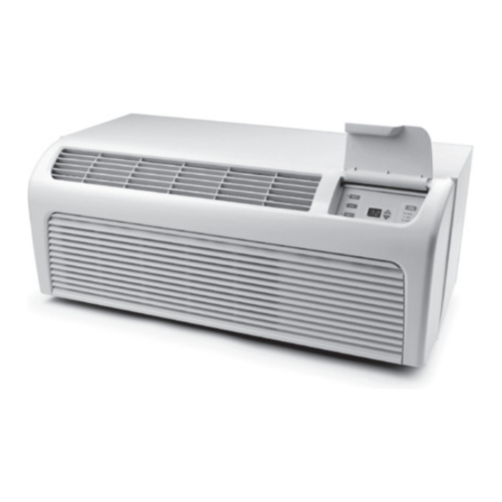
PACKAGE TERMINAL
AIR CONDITIONER/HEAT PUMP
I
NSTRUCTIONS
This manual must be left with the owner of the equipment.
is a registered trademark of Maytag Corporation or its related companies and is used under
license to Goodman Company, L.P., Houston, TX. All rights reserved.
•
© 2009, 2011 Goodman Company, L.P.
& O
Remember, it is your responsibility to install the product safely
and to know it well enough to be able to instruct a customer in
its safe use.
Safety is a matter of common sense...a matter of thinking before
acting. Most dealers have a list of specific good safety
practices...follow them.
The precautions listed in this Installation Manual are intended as
supplemental to existing practices. However, if there is a direct
conflict between existing practices and the content of this manual,
the precautions listed here take precedence.
Houston, TX 77056 •
'
M
WNER
S
ANUAL
www.amana-ptac.com
Advertisement
Table of Contents

Related Manuals for Amana DigiSmart PTC074E25AXXX


Summary of Contents for Amana DigiSmart PTC074E25AXXX
- Page 1 Maytag Corporation or its related companies and is used under license to Goodman Company, L.P., Houston, TX. All rights reserved. • Houston, TX 77056 • © 2009, 2011 Goodman Company, L.P. & O ’ WNER ANUAL www.amana-ptac.com...
-
Page 2: Table Of Contents
Contents Unit Features ... 2 Installation Instructions ... 5 Wiring ... 7 Operating Instructions ... 8 Maintenance and Cleaning ... 12 Obtaining Service ... 14 Normal Operating Sounds and Conditions ... 14 Configuration Settings ... 14 Configuration Chart ... 15 Diagnostic Maintenance &... -
Page 3: Control Panel
• Automatic freeze protection - Whenever power is sup- plied to the unit and the master switch is in the ON posi- tion, automatic freeze protection is active. If the unit senses temperature below 40°F, the fan motor and elec- tric strip heat are turned on. - Page 4 • Energy Management System Features Temperature Setback - This option can save energy dol- lars for unrented or unoccupied rooms by automatically setting back the operational temperatures. This mode of operation is selected through the configuration routine (see Configuration Settings section). NOTE: Temperature setback does not work with a wired remote thermostat.
-
Page 5: Installation Instructions
INSTALLATION INSTRUCTIONS To ensure that the unit operates safely and efficiently, it must be installed, operated and maintained according to these instal- lation and operating instructions and all local codes and ordi- nances or, in their absence, with the latest edition of the National Electric Code. - Page 6 Inside Outside Wall Sleeve Outside Wall Proper Sleeve Tilt OUTDOOR GRILLE An outside grille must be installed to direct air flow for proper unit operation and also protect the outdoor coil. The grille must be installed before installing the chassis. Refer to the Installa- tion Instructions supplied with the outdoor grille kit for a complete description of the installation procedure.
-
Page 7: Wiring
Slide the chassis into the wall sleeve until the chassis flanges contact the front edge of the wall sleeve. Screws Wall Sleeve (3 on each side of unit) Chassis Chassis Installation View 2 Secure the chassis to the wall sleeve using three screws on each side of the chassis to ensure a proper seal between the chassis and the wall sleeve. -
Page 8: Operating Instructions
VOLTAGE MEASUREMENTS Once the unit is properly wired, measure the unit supply voltage. Voltage must fall within the voltage utilization range given in Table 2. Operating Voltage Unit Voltage Voltage Utilization Range Rating Minimum 230/208 103.5 Table 2 - Operating Voltage OPERATING INSTRUCTIONS USERS CONTROLS A 7 button touch key pad, located behind the control door,... - Page 9 REMOTE CONTROL INPUTS The C, R, GL, W2, Y/W1, B/O, and GH terminals provide control inputs for a “manufacturer-approved” remote wall mounted thermostat. The “B” terminal can be configured to become “O” if needed see Configuration Settings For remote control thermo- stat operation, refer to the Remote Thermostat Operation section.
-
Page 10: Discharge Air Flow
Vent Door Shipping Screw Vent Control Lever Rotate the vent control lever to either open or close the damper. Vent Open Vent Door Lever Positions Hydronic Heat Installations To avoid the risk of freezing the steam or water coil during prolonged shut down periods, the vent door must be left closed when the outdoor temperature might fall below freezing. - Page 11 Do not install the thermostat where it may be affected by the following: • Dead spots behind doors, in corners or under cabinets • Hot or cold drafts from air ducts • Radiant heat from the sun, appliances, or fireplaces •...
-
Page 12: Maintenance And Cleaning
Maximum Wire Length Wire Size Maximum Length (AWG) Allowed 400 ft 600 ft 900 ft 1500 ft 2000 ft Table 5 - Maximum Wire Length for Remote Control Connection MAINTENANCE AND CLEANING WARNING OME LOCAL CONDITIONS AND ENVIRONMENTS CAN CAUSE FUNGI AND OTHER PTAC MATERIAL TO GROW INSIDE THE UNIT. - Page 13 Cabinet Front The cabinet front and discharge air grille can be cleaned with a water dampened cloth. Under no circumstances should hydro- carbon-based cleaners (e.g. acetone, benzene, naphtha gaso- line, etc.) or ammonia based cleaners be used to clean the front or air grilles.
-
Page 14: Obtaining Service
OBTAINING SERVICE In the event this unit requires repair or servicing beyond what is covered in this manual, contact an authorized service organiza- tion. To obtain an authorized servicer, contact your sales representa- tive or agency. NORMAL OPERATING SOUNDS AND CONDITIONS Water trickling sounds Water is picked up and distributed over the coil. -
Page 15: Configuration Chart
CONFIGURATION SETTINGS CHART Configuration Code Fan Operation Reverse Cycle Operation Room I.D. Digit 1 & 2 Room I.D. Digit 3 & 4 Wired or Wireless Occupancy Temp. Limiting Cool Temp. Limiting Heat English / Metric Temp Sensorless Un-Occ. Time 1st Un-Occ. Set Back Temp. 1st Un-Occ. -
Page 16: Diagnostic Maintenance & Status Report
DIAGNOSTIC MAINTENANCE & STATUS REPORT The Diagnostic Maintenance & Status Report provides detailed information on PTAC control operation and operational status including present modes, failures, airflow restriction warnings, operating temperatures, and past failures. The lower right hand dot on the center display flashes in this mode. In some cases the green LED located in the lower left hand corner of the touchpad below the OFF key will also be lit. -
Page 17: Diagnostic Codes
DIAGNOSTIC CODES CODE Freeze Protection Engaged. The room temperature measured by the wireless remote thermostat or indoor ambient thermistor active sensor falls below 40°F. Front Desk switch is closed. All outputs are switched off. Un-Configured Service Board - All operation held awaiting configuration Emergency Hydronic Engaged. - Page 18 THIS PAGE INTENTIONALLY LEFT BLANK...
- Page 19 THIS PAGE INTENTIONALLY LEFT BLANK...
- Page 20 Maytag Corporation or its related companies and is used under license to Goodman Company, L.P., Houston, TX. All rights reserved. • www.amana-ptac.com 5151 San Felipe, Suite 500 Houston, TX 77056 • © 2009, 2011 Goodman Company, L.P.