Table of Contents
Advertisement
Quick Links
Advertisement
Table of Contents

Related Manuals for Datavideo RMC-300A

Summary of Contents for Datavideo RMC-300A
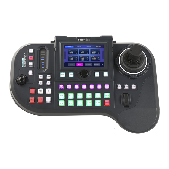
- Page 1 UNIVERSAL REMOTE CONTROL PANEL RMC-300A Instruction Manual...
-
Page 2: Table Of Contents
Video Mode ........................19 White Balance ....................... 19 Video Setting ......................... 20 Audio Setting ......................... 21 Serial Port Settings ......................22 RMC-300A........................23 Manage Device ......................... 23 System ..........................25 Language ........................25 Information ........................25 Serial Port ........................25... - Page 3 Datavideo Technologies will try to give correct, complete and suitable information. However, Datavideo Technologies cannot exclude that some information in this manual, from time to time, may not be correct or may be incomplete. This manual may contain typing errors, omissions or incorrect information.
-
Page 4: Fcc Compliance Statement
AC adapter. If you are not sure of the type of power available, consult your Datavideo dealer or your local power company. 8. Do not allow anything to rest on the power cord. Do not locate this unit where the power cord will be walked on, rolled over, or otherwise stressed. -
Page 5: Warranty
Warranty Standard Warranty Datavideo equipment is guaranteed against any manufacturing defects for one year from the date of purchase. The original purchase invoice or other documentary evidence should be supplied at the time of any request for repair under warranty. -
Page 6: Three Year Warranty
PC components are covered for 1 year. The three-year warranty must be registered on Datavideo's official website or with your local Datavideo office or one of its authorized distributors within 30 days of purchase. Disposal For EU Customers only - WEEE Marking This symbol on the product or on its packaging indicates that this product must not be disposed of with your other household waste. -
Page 7: Product Introduction
1.1 Features Remote Control via RS-422 or DVIP port Able to control up to 24 Datavideo PTZ/block cameras with 7 presets for each camera RGB keyboard for easy identification of keyboard functions User friendly UI on 5” touch screen for easy camera setup ... -
Page 8: System Diagram
1.2 System Diagram... -
Page 9: Connections And Controls
2. Connections and Controls In this chapter, we will first describe the rear panel ports for establishing connections with external devices. In the second section, we will discuss panel operations. 2.1 Rear Panel DVIP Control The DVIP port connects the camera controller directly to the PC or a network router via any RJ-45 cables, allowing the controller to control up to 24 cameras. - Page 10 DC In plug to the socket. 8 Serial Communication Ports On rear panel of the RMC-300A, there are 8 RJ-45 communication ports designed for establishing direction connection with PTZ cameras. The communication protocol used here is RS-422, allowing you to connect the controller to RS-422 ports of PTZ cameras (example: PTC-150) using any RJ-45 cables.
-
Page 11: Operation Panel
2.2 Operation Panel Camera Control VR Knob – Zoom ZOOM – Twist the joystick clockwise (to the right) or anti- clockwise (to the left) to zoom in or out the selected PTZ camera. Note: Make sure the LOCK button is not enabled. If the LOCK button LED is ON, the joystick is locked;... - Page 12 Joystick – PAN / TILT PAN – Move the joystick left or right to pan the selected PTZ camera from left to right or vice versa. TILT – Move the joystick up or down to tilt the selected PTZ camera up or down. PTZ Speed Selection Buttons The speed at which the selected camera moves can be chosen by pressing one of the three speed buttons (Fast,...
- Page 13 STR (Memory) Button Press the STR button to enter the RMC-300A into STORE MODE. When activated, this allows the current camera position to be stored in a chosen Preset Button by pressing the corresponding preset button. Press again to exit STORE MODE.
- Page 14 Press the AUTO IRIS button to enable auto iris adjustment of the selected camera. The 5 inch color touch screen displays the 4-in-1 OSD menu of camera, switcher, recorder and RMC-300A. The knob allows the user to manually adjust the camera’s shutter speed, focus, iris and gain.
-
Page 15: Switcher Control
SHUTTER Button IRIS Button Press to enable manual Press to enable manual adjustment of the shutter adjustment of the lens iris. speed. Note: Make sure the AUTO IRIS button is deactivated. FOCUS Button GAIN Button Press to enable manual Press to enable manual adjustment of the focus. -
Page 16: Camera Preset / Switcher Multi-Functional Composite Keys
Camera Preset / Switcher Multi-Functional Composite Keys The above composite keys allow you to save and recall PTZ settings in/from camera presets or activate the corresponding switcher functions as labelled. In this section, the Camera Preset buttons (PST 1/8 – PST 7/14) will be referred to as the PST button, the User Memory buttons (USER 1 and USER 2) for accessing the switcher’s system settings will be referred to as the USER button, the Keyer function buttons (KEYER 1 –... -
Page 17: Camera Selection Composite Keys 1/13 - 12/24
Camera Selection Composite Keys 1/13 – 12/24 Each Camera Selection Composite Key allows you to select up to two camera numbers as labelled. To switch between cameras 1-12 and cameras 13-24, simply press the Camera Shift button on the touch screen. Keyboard Brightness Control Keyboard Brightness Slider The LED style slider adjusts the keyboard brightness (currently... -
Page 18: Osd Menu
Locate and turn on the device’s power switch at the rear panel, after which the 5 inch color touch screen should display the 4-in-1 OSD menu of camera, switcher, recorder and RMC-300A. Note: The Switcher and Recorder functions are currently unavailable. -
Page 19: Camera Settings
Keys, which should illuminate light blue (the color of the Preset Shift button), indicating that the keys are activated for selection of presets 8 to 14. Camera Settings Tap camera icon to open the camera configuration page. The options are described below. Shutter Displays the camera’s shutter speed such as 1/30. -
Page 20: Video Setting
MWB Pro stands for manual white balance professional, allowing the user to manually adjust white balance by dragging red and green gain sliders on the configuration page. Video Setting Tap to open the camera video configuration page. Note: For PTC-150 and PTC-200 PTZ cameras, only video mode, video orientation and 3DNR are allowed for configuration;... -
Page 21: Audio Setting
Video Mode Currently unavailable. Video Orientation You can select the following video orientations as shown in the diagram below. Selecting OFF disables this option. Other Video Settings (Currently unavailable) 3DNR Contrast Sharpness Saturation Exposure Hue ... -
Page 22: Serial Port Settings
Serial Port Settings Tap the gear icon on the “Camera” page to open the serial port configuration page. Gear Icon Descriptions of the displayed options are outlined below. Please note that the “Serial Port Configs” page is currently unavailable. Baud Rate: Available rates are listed as follows. ... -
Page 23: Rmc-300A
3.2 RMC-300A The RMC-300A’s system configuration interface is illustrated below. Manage Device Once you are in the device management page, you should be able to see function keys for SCAN, LOAD and SAVE. - Page 24 Scan: After the Scan button is clicked, you will see a progress bar indicating the status of the scan. Once the scan is complete, all of the connected devices within the same network environment will be shown according to the order of the IP addresses. Load: System will load the latest pre-saved order of the devices.
-
Page 25: System
System On the System page, you will see the following function buttons. Language Currently unavailable. Information Tap to view the device information and upgrade device firmware. Serial Port Tap to enable/disable serial ports. -
Page 26: Network Setting
ON: Cameras 1 – 8 are reserved for RS-422 connections. Note: Cameras connected via DVIP while the serial port is enabled will be numbered from 9 – 24 as cameras connected to the serial ports take the priority over numbers from 1 – 8. OFF: Cameras 1 –... -
Page 27: Camera Tally
Model Name: RMC-300A (cannot be modified) DHCP: If enabled, the IP address will be automatically assigned by the router; if disabled, tap the following options to open a number keyboard and enter relevant settings. IP Address Network Mask ... -
Page 28: Joystick Speed Mode
The screen saver can be automatically activated after the device is idle for a period of time. The slider sets the time to activate the screen saver which is basically a black screen on the 5” LCD display. To deactivate the screen saver and wake up RMC-300A, simply tap any point on the screen. -
Page 29: Device Setup
4. Device Setup In this chapter, we will show you how you can connect the RMC-300A controller to multiple cameras via DVIP or RS-232 connection and operate cameras using your RMC-300A controller. Please note that you will be prompted of an error message if connection to the camera fails. - Page 30 First, connect the RMC-300A and Datavideo cameras to a router via DVIP ports using Ethernet cables. If the RMC-300A and the cameras are already set to DHCP, their IP addresses will be automatically assigned by the router. If the connection mode is set to static IP, you will then need to manually configure the network settings.
-
Page 31: Dhcp
DHCP Enable DHCP mode if you would like your device IP address be assigned dynamically by the router. Connect the RMC-300A to the router via the DVIP port. Static IP To connect using Static IP, simply disable DHCP mode and manually configure the following according to your network environment: ... - Page 32 4.2 RS-422 There are 8 RS-422 ports on the rear panel of RMC-300A. Each port can only connect one camera at a time. The diagram below best illustrates the connection between the RMC- 300A and multiple cameras via RS-422.
- Page 33 You can use a custom made RJ-45 cable to connect the RMC-300A to any Datavideo camera. Please make the connection cable according to the pinout information described below. RMC-300A Controller PTZ Camera Orange/White Orange/White Orange Orange Green/White Green/White Blue Blue...
- Page 34 After you’ve enabled the serial port, go back to the “Camera” page on the touch screen and tap the gear icon to open the Serial Port configuration page as shown below. Note: The “Serial Port Configs” page is currently unavailable. Below are descriptions of various RS-422 configuration options: Baud Rate: Available rates are listed as follows.
-
Page 35: Firmware Update
2. Plug the USB disk containing the latest firmware file into the USB 2.0 Firmware Upgrade Port, then turn ON the RMC-300A. 3. After the RMC-300A has been powered ON successfully, then at the top right corner of the UI on the LCD screen, tap RMC-300A then System. - Page 36 4. On the System page, tap the version number in Information. 5. On the Information page, tap the Update button.
- Page 37 6. While the firmware is being updated, you will be prompted as shown below. 7. Reboot your RMC-300A after the firmware has been successfully updated.
-
Page 38: Dimensions
6. Dimensions RMC-300A Unit: Millimeters (mm) -
Page 39: Specifications
7. Specifications Model Name RMC-300A Product Name Universal Remote Control Panel Maximum Camera Control Preset (Position) 14 for each camera Control Protocol DVIP, DHCP Client Connection to Camera RS-422, Ethernet Input/Output USB 2.0 x 2 10/100 Mbps Ethernet (RJ-45 connector) x 1... -
Page 40: Service And Support
Mar-19.2021 Version E3 Datavideo Technologies Co., Ltd. All rights reserved 2020...