Table of Contents
Advertisement
I
NTRODUCTION
Futaba CGY760R/CGY755 is gyro, 3-axis Stabilization System combining AVCS
gyro and head speed governor in one box designed for flybarless helicopters. Its cut-
ting edge MEMS (Micro Electro Mechanical System) sensor design, ultra high-speed
processing speed, and advanced PID control algorithm put it a league of it's own
ahead of all ahead of all other heading hold gyros in size, weight and performance.
CGY760R has a receiver function.
CGY755 has no receiver function.
This manual is for both CGY760R with receiver
function and CGY755 without receiver function.
If your gyro is CGY755, ignore the description of the receiver
function in this dotted box.
• No part of this manual may be reproduced in any form without prior permission.
• The contents of this manual are subject to change without prior notice.
• This manual has been carefully written. Please write to Futaba if you feel that any corrections
or clarifications should be made.
• Futaba is not responsible for the use of this product.
Setting
GPB-1
Setting
GPB-1
Receiver・Gyro・Governor
CGY760R
Receiving
Battery
Gyro・Governor
CGY755
Receiver
Battery
Receiving
Advertisement
Table of Contents

Related Manuals for FUTABA CGY760R


Summary of Contents for FUTABA CGY760R
-
Page 1: Introduction
• No part of this manual may be reproduced in any form without prior permission. • The contents of this manual are subject to change without prior notice. • This manual has been carefully written. Please write to Futaba if you feel that any corrections or clarifications should be made. - Page 2 20 cm de distance entre la source de rayonnement et votre corps. Declaration of Conformity (for EU) Hereby, Futaba Corporation declares that the radio equipment type is CGY760R/ CGY755 in compliance with Directive 2014/53/EU. The full text of the EU declara- tion of conformity is available at the following internet address: http://www.rc.futaba.co.jp/english/dl/declarations.html...
-
Page 3: Table Of Contents
• WRITE Screen ---------------------------------------------------------------------------------- 92 • S.BUS SERVO SETTING Screen ----------------------------------------------------------- 93 • VIA TRAINER FUNCTION --------------------------------------------------------------- 104 • 3D VIA TRAINER Screen FUNCTION LIST ----------------------------------------- 105 • GPB-1 SOFTWARE UPDATE ------------------------------------------------------------ 106 • MOUNTING OF CGY760R/CGY755 WITH SCREWS ------------------------------110 • Specifications -----------------------------------------------------------------------------------111... -
Page 4: Warranty And Repair Service (In U.s.a.)
If any difficulties are encountered while setting up or operating your gyro, please consult the instruction manual first. For further assistance you may also refer to your hobby dealer or contact the Futaba Service Center at the e-mail address, fax or tele- phone number listed below: Phone:1-256-461-9399, FAX:1-256-461-1059 E-Mail: service@futabaUSA.com... -
Page 5: Features
• Compatible with 1520 μS Analog (70 Hz), 1520 μS Digital (280 Hz), and 760 μS Digital (560 Hz) tail rotor servos. • Feed Forward Option allows the CGY760R/CGY755 to consider other control functions during operation. This results in more accurate corrections and precise operation. -
Page 6: Applicable Systems
• Feed Forward Option allows the CGY760R/CGY755 to consider other control functions during operation. This results in precise governing of the head speed. • Governor or Revolution Limiter mode selectable. • Supports gear ratios from 1.00 through 50.00. • Cutting edge control algorithm provides more consistent RPM governing. -
Page 7: Contents
ONTENTS Your CGY760R/CGY755 includes the following components: Type of set • CGY760R / GPB-1 / Governor set • CGY760R / GPB-1 set • CGY760R • GPB-1 SET CONTENTS GPB-1 Program Box *CGY connection cable X --- X *Transmitter connection cable... - Page 8 GPB-1 Gyro Program Box When setting up the gyro and the governor, connect it to the CGY760R/ CGY755 and use it. Do not install it on the helicopter. CGY760R : Has receiver function Mounting Pads (3) CGY755 : No receiver function...
-
Page 9: Replacement And Optional Items
CGY Connection Cable : 350 mm It is used to connect the CGY760R/CGY755 and the Gyro Program Box GPB-1. Receiver Connection Cable : 100 mm It is used to connect the CGY755 and the receiver. *Not included with CGY760R. Transmitter Connection Cable... -
Page 10: Precautions
Be sure that the two antennas are placed at 90 degrees to each other. 90˚ *The CGY760R has two antennas. In order to maximize sig- nal reception and promote safe modeling Futaba has ad- opted a diversity antenna system. This allows the receiver... - Page 11 Always check the transmitter and receiver battery voltage to ensure they have enough remaining capacity to complete the flight. Confirm that the CGY760R/CGY755 is operating in the correct mode. ABOUT BATTERIES: WARNING Newer high-end servos and other radio equipment are capable of...
- Page 12 (or similar) to prevent damage. ABOUT VIBRATION ISOLATION AND WATERPROOFING: The CGY760R/CGY755 is fixed with a dedicated mounting pad with good condition and the helicopter performs sufficient anti-vibration measures so as not to receive strong vibration at the time of flight.
- Page 13 The servo type parameters within the CGY760R/CGY755 must match the type of servo you are using. Incorrect setting may damage the CGY760R/CGY755 or the servos, possibly resulting in a loss of control during flight. Always allow the gyro to adjust to the surrounding environmental temperature before flight.
- Page 14 WARNING Never turn off the CGY760R/CGY755 while the GX (gyro) LED is blinking green at high speed (about 5/sec). *If the power is turned off while high-speed blinking, a data error will occur and all data will be initialized.
- Page 15 MACHINE MAINTENANCE: WARNING Even though the CGY760R/CGY755 is a high performance gyro and governor, it will be necessary to ensure that the helicopter mechanics are also in optimum operating condition. Please use the guidelines below and address all issues before installing and flying the CGY.
-
Page 16: Mounting / Part Name / Connecting
*The CGY760R/CGY755 should be mounted on a rigid platform, at least 6 in. [152 mm] away from a Nitro Engine. It is not necessary to mount the gyro near the main shaft of the model but it is very important that the mounting area chosen is rigid. -
Page 17: Mounting The Cgy(Cgy760R/Cgy755)
Mounting The CGY The CGY760R/CGY755 can be mounted in the orientation shown below unless it is installed so that the roll and pitch detection axis are aligned with the model. However, if there is a deviation of , equal to, or greater than 1/2 degrees, performance will degrade. In this step, please pay special attention to ensure optimum flight performance. - Page 18 Gyro Set Dir--- 4 AIL ----------N AIL ----------R ELE ---------N ELE ---------N RUD --------R RUD --------N AIL ----------R AIL ----------N ELE ---------R ELE ---------R RUD --------R RUD --------N Gyro Set Dir--- 5 *Depending on the type of mounting plate, it is also possible to mount as shown in the figure.
- Page 19 *Clean the oil on the bottom of the CGY760R/CGY755 and the machine mounting part with a solvent cleaner or the like. *The CGY760R/CGY755 is also designed to be screwed to the gyro mount. For sug- gested mounting methods, please refer to page 110 of this manual.
-
Page 20: Link Method With Transmitter (Fasstest / T-Fhss)
Link Method With Transmitter (FASSTest / T-FHSS) For CGY760R 1. Connect the CGY760R and GPB-1 and set the same mode set in as the transmitter linking the CGY760R communication mode on the "Receiver" screen. (See page 36) 2. Keep the transmitter and receiver close to each other and turn on the receiver with the transmitter in the link mode. -
Page 21: Connecting The Cgy
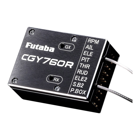
Indicates an error has occurred. For example, the gyro is not Blinking functioning correctly. If normal operation does not return after cycling the power off/on once again and/or replacing the battery, please contact our customer service department. For CGY760R RX (Receiver) LED State Solid green Normal operation. - Page 22 * When connecting the receiver, connect the battery only to CGY. S.BUS2 Tool *This diagram shows the various connections between the CGY760R/CGY755 and receiver, servo, or sensors. *S.BUS2 is a system that supports bidirectional communication from a telemetry sensor to a receiver by extending the conventional S.BUS.
-
Page 23: S.bus Channel Setting
Head Gain channels connected. When any of these functions are not used, it is necessary to set the channel number to "INH" within the CGY’s S.BUS menu. Do- ing so disables the function and enables the user of the value set in the CGY760R/ CGY755 menu accordingly. - Page 24 Magnet Operating Side Check Bring the magnet near the end of the sensor and check the operating side. * This is the side at which the displayed value increases in the "Revolution sensor test- ing" menu within the "Governor Basic Setting" section earlier in this manual. Install the magnet with this side facing the sensor.
- Page 25 3. Tighten the sensor stay together with the engine mounting flange. (Temporary assembly) 4. Select the mounting method so that the sensor does not touch the frame, or other parts of the model. Temporarily mount the sensor and select the magnet mounting position. 5.
- Page 26 Throttle Servo Linkage Precautions · To effectively use the governor, observe the following precautions when connecting the servo linkage. · Make the servo operating range as wide as possible. Make the throw of the transmit- ter EPA (ATV) function and AFR function as close as possible to 100%. ·...
-
Page 27: First Map
It is used to connect the CGY760R/CGY755 and the Gyro Program Box GPB-1. CAUTION Be sure to connect and disconnect the CGY760R/CGY755 and GPB-1 con- nection cable with the power off. Opening Screen When GPB-1 starts up with power on, the opening screen is displayed first. - Page 28 Each menu screen is displayed from the home screen. Home screen Press and hold the [Esc/Page] key Press and hold the [Esc/Page] key Press the [Enter] key Press the [Enter] key Press and hold the [ /+] key Press and hold the [ /-] key Pressing [ /+] and [ /-] keys simultaneously BASIC MENU screen...
-
Page 29: Home Screen
CREEN Home Screen Display On the home screen, basic information such as swash type, gyro operation mode, sensitivity and governor ON / OFF, engine operating time etc, are displayed. Home screen 1. Swash plate type Displays the swash plate type set in "SWH. BASIC" menu. 2. - Page 30 • If you set a condition switch channel, using the AFR function on that channel set a flat point curve for each flight condition. Then you can utilize all 5 flights conditions. Switch Channel Rate Neutral -100% -75% -25% 100% Cond3 Cond1 Cond2...
- Page 31 8. Engine running time Displays the running time of the engine. Up to 9,999 hours are displayed. Use the [ +] or [ -] key to move the cursor to the operation time display and press and hold [Enter] key to reset the display. The operation time is stored in memory even when the power is turned off until it is reset.
-
Page 32: Gpb-1 Screen
GPB-1 Screen This is the menu option for setting the GPB-1 display, etc. Pressing [ /+] and [ /-] keys GPB-1 screen simultaneously Home screen Press and hold the [Esc/Page] key Press the [Enter] key Press and hold the [Esc/Page] key DISPLAY screen Press the [ /+] or [ /-] key SOUND screen... - Page 33 DISPLAY (display setting of GPB-1) Set the contrast and brightness of the screen of the GPB-1 and the lighting time of the backlight. DISPLAY screen (1) CONTRAST Move the cursor to "CONTRAST" with the [ +] or [ -] key and press the [Enter] key to enter the setting mode.
- Page 34 SOUND (Key beep sound of GPB-1) This menu is used to turn on, or off, the sounds when the keys of the GPB-1 are uti- lized. Refer to page 33 to display the " SOUND " screen from the GPB-1 menu screen. SOUND screen (1) SOUND Set ON / OFF of key operation sound of GPB-1.
- Page 35 To change the "Receiver System" type, first power off the transmitter and receiver, and re-power the CGY760R/CGY755 while the transmitter is still in the OFF position. The only way to change the receiver type is by power cycling the gyro first.
- Page 36 For CGY760R NOTE: Updating can NOT be performed when the transmitter and the CGY760R communicate or when "Internal Rx" set- ting is INH. Turn on the power of the CGY760R with "Internal Rx" being ACT and transmitter power OFF.
- Page 37 GYRO UPDATE screen (3) Preparation for update -2 "GYRO UPDATE" screen from the GPB-1 menu screen. CAUTION Do not turn off the power or remove the bat- tery while updating. CGY and GPB-1 may be damaged. (4) Selection of CIU (Speed) Use the [ /+] or [ /-] key to move the cursor to "LOW SPEED (CIU2/3)"...
-
Page 38: Basic Menu
ASIC As the name suggests, this menu allows changes to the basic settings of CGY. Make sure to set each " BASIC MENU " . BASIC MENU screen Home screen Press and hold the [ /+] key Press and hold the [Esc/Page] key Press the [Enter] key Press and hold... -
Page 39: Sbus Basic Menu (S.bus Basic Setting)
INH (Inhibited). For example, if the Gain A/E and Gain RUD re- mote gain functions are not going to be used, then set them to [INH]. The CGY760R/ CGY755 will then allow you to make gain adjustments within the respective menu. - Page 40 By setting the condition switch on the channel with the AFR function of the transmitter and setting the point for each flight condition with the AFR point curve, you can switch the condition of CGY760R/CGY755 in conjunction with the flight condition switch of the transmitter.
- Page 41 From 2/3 CAUTION SBUS BASIC screen 3/3 Be sure to check the operation for all conditions 1 to 5 before flying. The setting of "Via transmitter CH" is possible only when the transmitter and the CGY are pow- ered off and the CGY is turned on. Be sure to connect and disconnect the CGY and Go to 1/3 from any GPB-1 connection cable with the power off.
- Page 42 (If you want to use the ELE2 port for purposes other than swash.) This selects the ELE2 servo types. There are three types of the servo driving frequency selection, AN:70 Hz, DG285 Hz, and 760 μS. All Futaba digital servos can be operated with fastest DG:285 Hz mode but some of other brands of servos do not support DG:285 Hz mode.
- Page 43 About Transfer Function Of Gyro Setting Data With this function, by connecting the transmitter and the GPB-1 with the transmitter connection cable, it is possible to wirelessly change the setting of the CGY mounted on the model via the transmitter. For the list of functions that can be changed, refer to page 105.
-
Page 44: Swh. Basic Menu (Swash Basic Setting)
ENU ( SWASH BASIC SETTING ) ASIC This menu is utilized to perform the basic setup of swash motion. " SWH. BASIC " screen from the " BASIC MENU " screen. The CGY760R/CGY755 is compatible with the following six types swash plate. FRONT H3-120 H3-140... - Page 45 From 5/5 From the "Pit.Low" of SWH. BASIC screen 5/5 SWH. BASIC screen 1/5 Go to 2/5 from any cursor position (1) Setup style 3D mode contains a proven set of parameters which are good for not only 3D but also F3C flying. F3C Mode and L.SCALE (Large scale model) Mode are for unique or special tuning types only.
- Page 46 This selects the swash servo types. There are four types or modes of the servo driving frequency selection, AN:70 Hz, DG:95 Hz, DG:140 Hz, DG285 Hz, and 760 μS. All Futaba digital servos can be operated with fast- est DG:285 Hz mode but some of other brands of servos do not support DG:285 Hz mode.
- Page 47 (5) Servo Dir #: Servo direction # Using different servo combinations will create the proper swash plate servo movement in electronic CCPM models (eCCPM). In the H3- xx swash mode, three of the swash servos directions are changed by pressing the [ /+] or [ /-] key. Choose the combination number which produces level swash plate travel with a collective pitch input from the transmitter.
- Page 48 *The current condition number of CGY is displayed. From 2/5 *The setting with "C#" display can be set for each condition. SWH. BASIC screen 3/5 1. Use the [ /+] or [ /-] key to move the cursor to "C#" and press the [Enter] key to enter the condition selection mode.
- Page 49 Cond (9) PIT. Rate: Rate adjustment The [PIT.Rate] is the amount of collective pitch travel allowed. A good starting range for Sport, 3D and F3C is +/-10 to +/-12 degrees. Use the [ /+] or [ /-] key to make an adjustment. Setting ranges: 0 ~ 100 Initial value: 50% From 3/5...
- Page 50 (12) STK. Dir AIL: Aileron operation Move the cursor to "STK. Dir AIL" by pressing the [ /+] or [ /-] key and press the [Enter] key to enter the setting mode. When "EXECUTE: En- ter (1 sec)" is displayed, move the aileron stick to the full right direction. Pressing the [Enter] key for about 1 second will memorize the aileron’s direction of motion.
- Page 51 (14) Pit. High: Pitch high memorizing This parameter saves the full positive collective pitch point into the CGY. Move the cursor to "Pit. High" by pressing the [ /+] or [ /-] key. Press the [Enter] key to enter the setting mode. "EXECUTE: Enter (1 sec)"...
-
Page 52: Flt. Tune Menu (Flight Tuning Setting)
ENU ( FLIGHT TUNING SETTING ) Flight tune sets control of helicopter roll (aileron) and pitch (elevator) axis. " FLT. TUNE " screen from the " BASIC MENU " screen. From 3/3 From the "HP.Auth." of *The current condition number of CGY is displayed. FLT. - Page 53 From 1/3 FLT. TUNE screen 2/3 Go to 3/3 from any cursor position Cond (3) Cnt. AuthAIL: Control Authority Aileron Aileron Control Authority changes the rate at which the gyro will try to achieve the set "CYC. Rt". A higher value will create a quicker acceler- ated reaction to a stick input to reach and stabilize to the "CYC.
- Page 54 Cond (5) EXPO.: Exponential Tune the exponential as desired to change the feel of the cyclic con- trols around center stick. Negative values soften control feel; Positive values increase sensitivity. The exponential rate is set by using the [ +] or [ -] key.
- Page 55 (7) ELE. Comp: Elevator pre compensation A helicopter that has a head that rotates clockwise, will exhibit a tenden- cy whereby the nose will be pulled towards the disk with positive blade pitch. Conversely, the helicopter will push the nose away from the rotor disk during negative pitch inputs.
-
Page 56: Rud. Basic Menu (Rudder Gyro Basic Setting)
Setting on transmitter side The following transmitter setting example shows the case of using Futaba GY gyro mixing. Please read in accordance with your system. 1. Enable rudder gyro mixing. - Page 57 From 2/2 From the "Work Mode." of RUD. BASIC screen 2/2 RUD. BASIC screen 1/2 WARNING Go to 2/2 from any The servo type parameter within the CGY must cursor position match the type of servo you are using. Incorrect settings may damage the CGY or the servo.
- Page 58 (3) Srv. Limit: Limit setting When the CGY is in the "Srv.Limit" parameter mode, the gyro will no longer operate and the tail servo will always center when the tail rotor stick is released. Always exit the setup functions before attempting to fly the model.
- Page 59 From 1/2 RUD. BASIC screen 2/2 Go to 1/2 from any cursor position (4) Work Mode: Gyro working mode The available choices are CMT, Normal or AVCS. The CMT mode will allow you to select either AVCS or Normal mode via the transmitter. In Normal mode the gyro will always operate in Normal Rate Mode, and when AVCS is selected, it will always operate in AVCS Mode.
-
Page 60: Gov. Basic Menu (Governor Basic Setting)
ENU ( GOVERNOR BASIC SETTING ) ASIC This menu sets the governor’s fundamental functions. The menu Servo limit point setting must be set first. " GOV. BASIC " screen from the " BASIC MENU " screen. From 6/6 From the "SBUS2 rpm Slot" Note: When using the governor function, be sure of GOV. - Page 61 (3) Pole Num.: Pole number This parameter is used when using a direct phase sensor attachment to a brushless motor lead. Input the motor pole count as specified by the brushless motor manufacturer. When using any revolution sensor other than a direct phase sensor type, set the pole number to 2 p. Note: For nitro use, set to 2 p.
- Page 62 (5) RPM set.: RPM setting Setting the main rotor RPM. This is calculated by engine revolution with the gear ratio of the main shaft. When the rotation speed can be set with the governor mixing function of the transmitter, it is necessary to first match the display rpm value of 1-2-3 of "RPM Set"...
- Page 63 (7) ON/OFF sw.: Governor on/off switch This parameter allows the user to turn the governor on or off via a switch on the transmitter. Pressing the [ /+] or [ /-] key activates the function. Choose INH if you do not want to use it. When turning on / off governor with switch Select the ON / OFF switch channel with "GOV sw channel"...
- Page 64 From 2/6 WARNING GOV. BASIC screen 3/6 When using the CGY for the first time, or when making changes in the throw of a servo and its link- age, always perform the limit setting operation. (9) Lim. set: Servo limit point setting Servo limit point setting defines the overall travel Go to 4/6 from any range for the throttle servo.
- Page 65 (11) SenseTyp: Sensor type Select the type of governor sensor. Nitro (BPS-1 backplate; Magnet Type) 1:1 Magnet "1:1 Mag" (Magnet type applied to helicopter part that turns at the same RPM as the main rotor) HPoleEP: For Electric motors 8 poles and above LPoleEP: For electric motors 6 poles.
- Page 66 (14) Rev. Sensor: Revolution sensor testing This menu is utilized to ensure that the revolution sen- From 4/6 sor is functioning properly. The display for this testing GOV. BASIC screen 5/6 is found in: GOV BASIC 5/6. In order to test the sensor, do NOT start the engine. Instead, we recommend turning the engine over by hand or the utilization of a starter.
-
Page 67: Governor Speed Setting
* Governor Speed Setting If the governor switch is ON when the power is turned ON, the governor will not turn ON. Once you turn off the ON state, the governor is ready for operation. Always turn off the governor when starting the engine. The CGY’s rpm selection is accomplished by setting the channel in section (8) "... -
Page 68: Recommended Gyro Gain Setting
ECOMMENDED ETTINGS Recommended gain settings: The optimum sensitivity is the position just before the gyro starts hunting. To achieve this optimum setting, it is necessary to adjust the gyro gain settings after actually fly- ing the helicopter. Recommended Gyro Gain Size Rotor Head Gyro RUD Gyro... - Page 69 WARNING Always level the swash plate using the cyclic stick before applying throttle and spooling up the main rotor blades. During takeoff small corrections may be necessary. If you make large corrections while the helicopter is on the ground, it may tip over since the helicopter is firmly on the ground and the gyros are over- compensating due to the lack of movement.
-
Page 70: Tips Using The Governor With Electric Models
IPS FOR SING THE OVERNOR LECTRIC ODELS WARNING Safety Reminder: Remove both main and tail blades from the model and/or disengage the motor’s pinion from the main gear before proceeding with any electric governor set up. Make sure your ESC is configured for external governor use. Refer to the own- er’s manual for your ESC. -
Page 71: Transmitter Rotor Head Gyro Gain Set-Up
Transmitter Set-up for adjusting cyclic gains via the transmitter. Using the Remote Gain Functions (roll, pitch and yaw) 1. Some Futaba transmitters contain auxiliary gain functions for aileron, elevator and yaw. Please refer to your transmitter’s instruction manual. Assign the Gyro (RUD), Gyro (Rotor Head replaces AIL/ELE) channels within the transmitter. -
Page 72: Expert Menu
XPERT This menu enables the user to further refine the gyro and governor settings. EXPERT MENU screen Home screen Press and hold the [ /-] key Press and hold the [Esc/Page] key Press the [Enter] key Press the [ /+] or [ /-] key Press and hold the [Esc/Page] key SWH.DETAIL screen... -
Page 73: Rud. Expert Menu (Rudder Gyro Expert Setting)
XPERT ENU (RUDDER GYRO EXPERT SETTING) The rudder Expert menu allows for further refinement of the tail rotor gyro perfor- mance. " RUD. EXPERT " screen from the " EXPERT MENU 3D " screen. From 5/5 From the "Sens. Model" of RUD. - Page 74 From 1/5 RUD. EXPERT screen 2/5 Go to 3/5 from any cursor position (3) CNT. DlIn: Control delay in This parameter sets the delay as you move the stick from neutral toward left or right. Larger values result in a softer tail rotor feel off center. This parameter must be adjusted individually for LEFT and RIGHT tail rotor commands.
- Page 75 From 2/5 RUD. EXPERT screen 3/5 Go to 4/5 from any cursor position (5) ANG: Pirouette speed This parameter adjusts the maximum pirouette speed of the tail rotor that the gyro will allow at 100% dual rate. Use the [ /+] or [ /-] key to adjust the maximum commanded pirouette rate.
- Page 76 (6) ACC Gain: F/F mixing acceleration gain In low head speed situations where a lot of F/F Mixing might be needed, acc. gain boosts the input and removes it immediately after to help cure the sudden change in torque, but it does not allow the large tail rotor input to alter the axial behavior of the helicopter.
-
Page 77: Flt. Expert Menu (Cyclic Gyro Expert Setting)
ENU ( CYCLIC GYRO EXPERT SETTING ) XPERT The " FLT.EXPERT " menus allow further refinement of cyclic gyro performance. " FLT. EXPERT " screen from the " EXPERT MENU 3D " screen. From 2/2 From the "RESET" of FLT. EXPERT screen 2/2 *The current condition number of CGY is displayed. - Page 78 Cond (3) StopTune E: Stop tune elevator Cyclic stop tuning on the elevator axis. If the helicopter, after an elevator flip, continues to coast, lowering "StopTune E" will create a harder stop action to remove the coasting. If the helicopter continues to coast after an elevator flip, lowering the "Stop tune E"...
- Page 79 (6) RESET : FLT tune data reset This resets the "FLT.Tun" setting back to the defaults. Move the cursor to "RESET" by pressing the [ /+] or [ /-] key, and press the [Enter] key to enter the reset mode. With "EXECUTE: Enter (1 sec)" displayed, press and hold the [Enter] key for about 1 second to initialize "FLT.Tun"...
-
Page 80: Swh. Detail Menu (Swash Detail Setting)
ENU ( SWASH DETAIL SETTING ) ETAIL The swash detail setting is used to keep the swash plate level at high and low col- lective pitch to cyclic interactions and cyclic pitch to collective pitch interactions. " SWH. DETAIL " screen from the " EXPERT MENU 3D " screen. From 2/2 From the "RESET"... - Page 81 (3) PIT ELE2: collective pitch 2nd elevator mixing rate This parameter adjusts the pitch to 2nd elevator mixing rate. The rates can both be adjusted individually for both full high and low collective positions. Note: This setting is only available if the H4-xx swash mode has been selected.
- Page 82 From 2/7 SWH. DETAIL screen 3/7 Go to 4/7 from any cursor position (7) ELE PIT: elevator collective pitch mixing rate During back and forward elevator inputs at middle collective, check if the swash plate is raising or lowering during the input. If it is moving use the [ /+] or [ /-] key to raise or lower the swash plate to match the middle point during elevator inputs.
- Page 83 From 3/7 SWH. DETAIL screen 4/7 Go to 5/7 from any cursor position (10) AIL High / AIL Low: Linkage compensation aileron At HIGH pitch and LOW pitch check to make sure that the swash plate is staying level on the elevator and collective axis when using aileron inputs.
- Page 84 From 4/7 SWH. DETAIL screen 5/7 Go to 6/7 from any cursor position (12) ELE High / ELE Low: Linkage compensation elevator At both the HIGH pitch and LOW pitch check to make sure that the swash plate is staying level on the aileron and collective axis when using elevator inputs.
- Page 85 From 5/7 SWH. DETAIL screen 6/7 Go to 7/7 from any cursor position (14) Speed Comp: Speed compensation In 120 degrees CCPM all servos do not travel the same distance on elevator input. Having previously set the ELE-PIT and ELE-AIL param- eters, if during rapid movement of the elevator axis the swash plate is not staying level, use the [ /+] or [ /-] key to match all servo speeds.
- Page 86 From 6/7 SWH. DETAIL screen 7/7 Go to 1/7 from any cursor position (16) RESET : Swash detail data reset This resets the "SWH.DETAIL" setting back to the defaults. Move the cursor to "RESET" by pressing the [ /+] or [ /-] key. Press the [Enter] key to enter the reset mode.
-
Page 87: Gov. Expert Menu (Governor Expert Setting)
ENU ( GOVERNOR EXPERT SETTING ) XPERT This menu sets the Governor Expert parameters, allowing the user to further refine the governor settings. " GOV EXPERT " screen from the " EXPERT MENU 3D " screen. From 3/3 From the "RESET" of GOV. - Page 88 (4) Yaw. Comp: Governor working mode Yaw compensation allows the governor to more rapidly correct for changes in power demands of the model resulting from yaw input. Set the mode to match the gyro installation direction. Select from: CW/TOP, CW/ BOTM, CCW/TOP, CCW/BOTM by pressing the [ /+] or [ /-] key.
- Page 89 From 1/3 GOV. EXPERT screen 2/3 (6) Revo. Up Dly: Revolution change up delay How quickly the RPM changes when increasing RPM between two different RPM conditions and flight modes. A higher number slows the RPM change rate; a lower value speeds up the RPM change rate. Go to 3/3 from any Setting ranges: 2 ~ 40 Frm Initial value: 8 Frm...
- Page 90 (10) BFS. Volt: Battery F/S voltage setting This parameter sets the battery fail safe and low battery alarm voltage levels, or thresholds. Set the proper voltage as determined by the bat- tery type. The battery characteristics are different depending on cell type/chemistry.
-
Page 91: Write Screen
- The data to be written is the " BASIC " menu and " EXPERT " menu. - With the exception, the setting of ACT / INH of " Internal " on the " RECEIVER " screen of the GPB-1 menu is written (for CGY760R). WARNING After writing, if the setting is "INH", the internal receiver is operating without... -
Page 92: S.bus Servo Setting Screen
S.BUS SERVO SETTING Screen An S.BUS servo can memorize the channel and various settings you input. Servo setting can be performed on the GPB-1 screen by wiring the servo as shown in the figure. *With some S.BUS(2) servos, there are some functions which cannot be used. If a function cannot be used, the display screen will change. - Page 93 From the opening screen, hold down the [ /+] key to display the SBUS servo screen. Opening screen SBUS servo screen Press and hold the [ /+] key Press and hold the [Esc/Page] key S.BUS / S.BUS2 servo recall, writing, initialization (1) RECALL Load the setting data of S.BUS servo connected to GPB-1.
- Page 94 (2) WRITE Write the data set with GPB - 1 to the connected S.BUS servo. Move the cursor to "WRITE" by pressing the [ /+] or [ /-] key. Press the [Enter] key to enter the Press the [Enter] key writung mode.
- Page 95 Change servo type Changing the servo pulse width from 1520 to 760 is possible with the servo type function. Display of "servo type" when reading * When "RECALL" is executed, the servo type name is displayed on the left side of the screen, and the current 760 or 1520 type is displayed below it.
- Page 96 Notes on servo set to 760 μS To connect the servo set to "DG: 760" or "SWH: 760" to AIL / ELE / PIT / ELE2, set the servo type to "DG: 760". To use the servo set to "DG: 760" or "RUD: 760" for RUD, set the servo type to "DG: 760".
- Page 97 Description of function of each parameter With some S.BUS(2) servos, there are some functions which cannot be used. If a function cannot be used, the display screen will change. From 4/4 From the "BUZZER" of SBUS SERVO screen 4/4 Displays the ID of the servo whose parameters are to be read. SBUS SERVO screen 1/4 It cannot be changed.
- Page 98 From 1/4 SBUS SERVO screen 2/4 (3) TRAVEL (LEFT / RIGHT) Go to 3/4 from any cursor position The left and right travels centered about the neutral position can be set independently. (4) NEUTRAL The neutral position can be changed. When the neutral offset is large value, the servo's range of travel is restricted on one side.
- Page 99 From 2/4 SBUS SERVO screen 3/4 Go to 4/4 from any cursor position (7) REVERS The direction in which the servo rotates can be changed. Setting: NORM / REV (8) TYPE When "Retractable" is selected and the servo has been continu- ously stopped for 30 seconds, the dead band expands and unnec- essary hold current due to external force is eliminated.
- Page 100 (11) BOOST - ON/OFF The minimum current applied to the internal motor when starting the servo can be set. Since a small travel does not start the motor, it essentially feels like the dead band was expanded. The motor can be immediately started by adjusting the minimum current which can start the motor.
- Page 101 From 3/4 SBUS SERVO screen 4/4 Go to 1/4 from any cursor position (13) STRACTCH (Stretcher) The servo hold characteristic can be set. The torque which attempts to return the servo to the target position when the current servo position has deviated from the target position can be adjusted.
- Page 102 The following can be displayed and set only when the type setting is "OLP". (15) Trq This is the torque for working OLP. Setting: 10% - 100% Initial setting: 100% 100% is the maximum torque of the servo which you are setting. (16) TIME This is the time for working OLP.
-
Page 103: Via Trainer Function
UNCTION When using " Via Trainer " which wirelessly transfers gyro setting data from the transmitter, connect the transmitter and the GPB-1 as shown below. Futaba transmitters other than T32MZ have only one connection. Transmitter Connection Cable Trainer jack of the transmitter. -
Page 104: Via Trainer Screen Function List
3D V RAINER CREEN UNCTION -FLT. TUNE Base Gain: Gyro base gain setting (page 53) CYC. Rt: Cyclic rate setting (page 53) Cnt. AuthAIL: Control Authority Aileron (page 54) Cnt. AuthELE: Control Authority Elevator (page 54) EXPO.: Exponential (page 55) FLT. -
Page 105: Gpb-1 Software Update
* The following optional products are required for the update. · CIU-2 or CIU-3 · Cable for CGY760R/CGY755/GY701/GY520 or DSC cable for update · Receiver battery 1. Download the CGY760R/CGY755 update file from our website or your local distribtor's website. 2. Extract the zip file on your computer. main.bin... - Page 106 GPB-1 side PC side 5. When using the CIU-3, hold down 4. Start an executable file by a PC. the [Enter] and [Esc / Page] keys of the GPB-1 and turn on the power. Updata(Highspeed) CIU-3 Release the [Enter] and the [Esc / Updata(Lowspeed) CIU-2 Page] keys when the backlight of...
- Page 107 PC side GPB-1 side When using the CIU-3 When using the CIU-2 Click [WRITE] WRITE CAUTION D o n o t t u r n o f f t h e p o w e r o r r e - m o v e t h e b a t t e r y w h i l e u p d a t i n g .
- Page 108 PC side GPB-1 side Wait for about 50 seconds - 5 minutes. 6. Tu r n o ff t h e p o w e r a f t e r t h e completed message " SUCCESS " appears. 7.
-
Page 109: Mounting Of Cgy760R/Cgy755 With Screws
CGY W OUNTING CREWS WARNING If using screws to mount the CGY to the helicopter, it is imperative to ensure that the machine does not vibrate excessively. *Please do not mount with machine screws with vibration, please mounting with a dedi- cated mounting pad. -
Page 110: Specifications
Current Drain: 85 mA (When receiving, no servo, no RPM sensor) Operating Temperature: 14°F to 113°F (-10°C to +45°C) Size (CGY760R) : 1.055 in. [26.8 mm](W) / 1.476 in. [37.5 mm](L) / 0.63 in. [16 mm](H) Weight (CGY760R) : 0.713 oz [20.2 g]... - Page 111 Size: 2.126 in. [54 mm](W)/3.543 in. [90 mm](L)/0.6102 in. [15.5 mm](H) Weight(RPM sensor): 1.88 oz [53.3 g] * The operating voltage shown only applies to the CGY760R/CGY755 and GPB-1. Always verify that your receiver, servos, tail rotor servo, switch and any other electronic components used in your installation are capable of oper- ating at the voltage you plan to use.