
Related Manuals for Nelson CM-2201


Summary of Contents for Nelson CM-2201
- Page 1 NELSON HEAT TRACE NELSON ™ CM-2201/CM-2202 HEAT TRACE CONTROLLERS Installation and Operating Instructions...
- Page 2 5.6 Current-Limiting Feature 5.7 Ground Faults 5.8 Soft Start Feature Control Modes 6.1 On-Off Control 6.2 Proportional Control 6.3 Forced Control Feature Programming 7.1 Setpoints 7.2 Heater Setup 7.3 System Setup 8.0 Communications ©2018 Nelson Heat Tracing Systems www.nelsonheaters.com GA2497 Rev.6...
-
Page 3: Table Of Contents
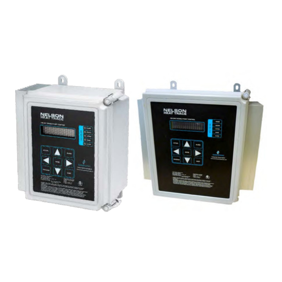
Appendix B – Wiring Diagrams Appendix C – Typical Installation Diagram Appendix D – Mounting Details Appendix E – Modbus Address List Appendix F – ASCII Table Appendix G – RTD Tables Appendix H – Warranty ©2018 Nelson Heat Tracing Systems www.nelsonheaters.com GA2497 Rev.6... - Page 4 Introduction CM-2201/CM-2202 1.0 Introduction The Nelson Heat Trace CM-2201 is designed to monitor and control one heating circuit in ordinary and Class I, Division 2, Class I, Zone 2, and Zone 2 hazardous locations. The CM-2202 can monitor/control two heating circuits in those same locations.
- Page 5 GFI, etc.) are open for monitoring. The power supply for the CM-2201 is derived from the If the password is “Enabled”, going directly to the power provided for the load. However, the power supply for parameter to be changed, and pressing the ‘up’...
- Page 6 CM-2201/CM-2202 5.1 Display 5.1.2 Navigation for CM2202 The CM-2201/CM-2202 utilizes a 2-line x 16-character alphanumeric display viewable from the front keypad. The top The CM2202 can monitor/control two separate heating line is reserved for the function or operation and the circuits (channels).
- Page 7 This short energization period is repeated and eventually increased; after a few minutes, the cable is usually warm enough such that the resistance has increased and the current decreased to the point where it can be continuously energized. ©2018 Nelson Heat Tracing Systems www.nelsonheaters.com GA2497 Rev.6...
- Page 8 CM-2201/CM-2202 6.0 Control Modes Forced Control Feature The CM-2201/CM-2202 allows the user to select different This control method simply allows the user to force the cable on or control modes based on their individual process control off as desired using an external signal (e.g. +5 VDC or 24 VAC) parameters.
- Page 9 1. Display Mode: All 2. Range: -50C to Maintain Temperature, Off, -58°F to Maintain Temperature, Off 3. Default: 5°C or 41°F 4. Restrictions: Message does not exist if Maintain Temperature is set to Off. ©2018 Nelson Heat Tracing Systems www.nelsonheaters.com GA2497 Rev.6...
- Page 10 1. Display Mode: All 1. Display Mode: All 2. Range: Yes, No 2. Range: Ground Fault Alarm to 500mA, Off 3. Default: No 3. Default: 50mA ©2018 Nelson Heat Tracing Systems www.nelsonheaters.com GA2497 Rev.6...
- Page 11 2. Range: 1 C° to 5 C°, 1 F° to 10 F° 1. Display Mode: Advanced 3. Default: 2 C° or 5 F° 2. Range: 16 Characters (CM-2201) 4. Note: Deadband is disabled for Proportional 12 Characters (CM-2202) Control mode.
- Page 12 Auto Test is a feature that exercises the system by 1. Display Mode: Advanced automatically applying power to the heater at 2. Range: Normally Open, Normally Closed specified time intervals. If an alarm condition is detected 3. Default: Normally Open ©2018 Nelson Heat Tracing Systems www.nelsonheaters.com GA2497 Rev.6...
- Page 13 Celsius degrees (C°) or all the heaters Fahrenheit degrees (F°). Heater status Alarm status of 1. Display Mode: Advance the heater 2. Range: Celsius, Fahrenheit Heater temp Temperature of 3. Default: Celsius the heater ©2018 Nelson Heat Tracing Systems www.nelsonheaters.com GA2497 Rev.6...
- Page 14 This message displays the name of the sub-menu when 1. Display Mode: Advanced entered. 2. Range: Autotest cycle, Now, Disabled 1. Display Mode: Advanced 3. Default: Disabled 2. Range: N/A 3. Default: N/A ©2018 Nelson Heat Tracing Systems www.nelsonheaters.com GA2497 Rev.6...
- Page 15 CM-2201/CM-2202 Communications 8.0 Communications The Nelson Heat Trace CM-2201 supports a subset of the Modbus RTU protocol format that provides monitoring, ® programming, and control functions using Read (03) and Write (05-06) register commands. General Information Serial Port: Select the serial port that corresponds to your RS-485 adapter.
-
Page 16: Troubleshooting
Ensure that the RTD extension wire shield is terminated at one end only, normally using the terminal block provided at the terminal board. ©2018 Nelson Heat Tracing Systems www.nelsonheaters.com GA2497 Rev.6... - Page 17 32°F (0°C) depending on the actual resistance of the test resistor if RTD TYPE is set to 100 Ω Platinum. Any resistor may have a +/- 10% tolerance. ©2018 Nelson Heat Tracing Systems www.nelsonheaters.com GA2497 Rev.6...
-
Page 18: Common Warnings/Alarms
9.4 Common Warnings/Alarms - What to Look for 9.4.5 Power Limiting (Current Limiting) The CM-2201/CM-2202 has a wide range of warning This alarm indicates that the solid-state relay is limiting the and alarming features that may be selectively enabled or... - Page 19 CM2201/CM2202 should be replaced and returned to the factory for repair. Cause of Alarm: • The CM-2201/CM2202 cannot bypass the failed area of its memory and has loaded factory defaults into this failed area . ©2018 Nelson Heat Tracing Systems www.nelsonheaters.com...
-
Page 20: 10.0 Maintenance
Maintenance CM-2201/CM-2202 10.0 Maintenance The CM-2201/CM-2202 should be regularly maintained as follows: a) Check fit of door gasket and adjust as required. Clean door gasket. b) Verify that moisture is not entering enclosure; repair as required. c) Check terminals to ensure connections are secure. -
Page 21: Appendix A - Specifications
2. 30VDC@ Max. 0.1 Amps (Solid State Relay - requires Min. 50mA load) Agency Approval for Hazardous Locations: cCSAus Class1, DIV.2, Groups A, B, C, D Class 1, Zone 2: IIC Temperature Code: T4 (135 °C) ©2018 Nelson Heat Tracing Systems www.nelsonheaters.com GA2497 Rev.6... -
Page 22: Appendix B - Wiring Diagrams
1. Solid State Contact 2. Install Jumper at JP1 (120 OHM Resistor) on both terminals if CM-2201 is last device on network. Else install jumper on one terminal only of JP1. 3. If “Force “ feature is activated by external “dry contact”, use “+5V” and “IN” terminals; Ground connection is not required. If activated by external voltage signal, use “IN”... - Page 23 Controller powered in parallel with CH.1 Controller powered in parallel with CH.2 Jumper CONN4-L1 to CONN3-L1 Jumper CONN5-L1 to CONN3-L1 & & Connect power supply directly to conn3 CONN4-L2/N to CONN3-L2/N CONN5-L2/N to CONN3-L2/N ©2018 Nelson Heat Tracing Systems www.nelsonheaters.com GA2497 Rev.6...
-
Page 24: Appendix C Typical Installation Diagram
Appendices CM-2201/CM-2202 Appendix C Typical Installation Diagram ©2018 Nelson Heat Tracing Systems www.nelsonheaters.com GA2497 Rev.6... -
Page 25: Appendix D Mounting Details
Appendices CM-2201/CM-2202 Appendix D Mounting Details CM-2201 Mounting Details CM-2202 Mounting Details ©2018 Nelson Heat Tracing Systems www.nelsonheaters.com GA2497 Rev.6... -
Page 26: Appendix E - Modbus Address List
= x per 1 Hour (1 to 720) 40017 Auto Test Cycle = 32767 if Set to Off = x per 1 Second (5 to 600) 40018 Display Time = 32767 if Set to Off ©2018 Nelson Heat Tracing Systems www.nelsonheaters.com GA2497 Rev.6... - Page 27 GF Test (CH.2) 01 = Now 10 = Disable 0 = Fixed Resistance Heater Type (CH.2) 1 = Self Regulating 0 = Normally Open Alarm Contact (CH.2) 1 = Normally Closed Reserved ©2018 Nelson Heat Tracing Systems www.nelsonheaters.com GA2497 Rev.6...
- Page 28 40206 (ch2) = 32767 if Set to Off Deadband in °F 40207 = x per 1°F (1 to 10) (ch2) Deadband in °C 40208 = x per 1°C (1 to 5) (ch2) ©2018 Nelson Heat Tracing Systems www.nelsonheaters.com GA2497 Rev.6...
- Page 29 = x per 1 Hour (1 to 24) 40224 (ch2) = 32764 if Set to Disable =32765 if Set to Continuously 40225 Reserved Heater Name 12-character limit. See 40191-40198 190-197 Appendix E for ASCII chart. (ch2) ©2018 Nelson Heat Tracing Systems www.nelsonheaters.com GA2497 Rev.6...
- Page 30 Max Temp in °C = 32765 if RTD Fail = 32763 if Undetected * = x per °F 40059 Min Temp in °F = 32765 if RTD Fail = 32763 if Undetected * ©2018 Nelson Heat Tracing Systems www.nelsonheaters.com GA2497 Rev.6...
- Page 31 16384 = Reserved 40103-40104 102 – 103 Alarm Stack 17 32768 = Self Check Failure 65536 = GFI test failure 40105-40106 104 – 105 Alarm Stack 18 40107-40108 106 – 107 Alarm Stack 19 ©2018 Nelson Heat Tracing Systems www.nelsonheaters.com GA2497 Rev.6...
- Page 32 = 32763 if Undetected * RTD-B Temp in °F = x per °F (ch2) = 32765 if RTD Fail 40231 = 32763 if Undetected * 40232 RTD-B Temp in °C = x per °C ©2018 Nelson Heat Tracing Systems www.nelsonheaters.com GA2497 Rev.6...
- Page 33 246-247 (ch2) = 0x7FFFFFFF Out of Range Heater On Time = x per 1 Hour 40249-40250 248-249 (ch2) = 1500000 Out of Range Heater on % 40251 = x per 1% (ch2) ©2018 Nelson Heat Tracing Systems www.nelsonheaters.com GA2497 Rev.6...
- Page 34 Alarm Stack 17 40284-40285 283 – 284 (ch2) Alarm Stack 18 40286-40287 285 – 286 (ch2) Alarm Stack 19 40288-40289 287 – 288 (ch2) Alarm Stack 20 40290-40291 289 – 290 (ch2) ©2018 Nelson Heat Tracing Systems www.nelsonheaters.com GA2497 Rev.6...
- Page 35 Log Stack 17 40324-40325 323 – 324 (ch2) Log Stack 18 40326-40327 325 - 326 (ch2) Log Stack 19 40328-40329 327 – 328 (ch2) Log Stack 20 40330-40331 329 - 330 (ch2) ©2018 Nelson Heat Tracing Systems www.nelsonheaters.com GA2497 Rev.6...
- Page 36 = Set "On (0xFF00)" to Reset 00178 Reset Self Check Fail Alarm = Set "On (0xFF00)" to Reset 00179 Reset GFI Test Alarm = Set "On (0xFF00)" to Reset 00180-00184 179-183 Reserved ©2018 Nelson Heat Tracing Systems www.nelsonheaters.com GA2497 Rev.6...
- Page 37 Reset RTDB Fail Alarm (Ch2) = Set "On (0xFF00)" to Reset 00212 Reset Self Check Fail Alarm (Ch2) = Set "On (0xFF00)" to Reset 00213 Reset GFI Test Alarm (Ch2) = Set "On (0xFF00)" to Reset ©2018 Nelson Heat Tracing Systems www.nelsonheaters.com GA2497 Rev.6...
-
Page 38: Appendix Fascii Table
Appendices CM-2201/CM-2202 Appendix F ASCII Table ©2018 Nelson Heat Tracing Systems www.nelsonheaters.com GA2497 Rev.6... -
Page 39: Appendix G - Rtd Tables
132.04 155.82 -167 32.59 -104 58.63 83.88 108.18 132.42 156.19 -166 33.01 -103 59.04 108.57 132.80 156.57 -165 33.43 -102 59.44 84.27 108.96 133.18 156.94 -164 33.85 -101 59.85 84.67 109.35 133.56 ©2018 Nelson Heat Tracing Systems www.nelsonheaters.com GA2497 Rev.6... - Page 40 234.22 255.27 275.89 296.08 191.18 213.09 234.56 255.61 276.23 296.41 191.54 213.44 234.91 255.95 276.56 296.74 191.90 213.80 235.26 256.29 276.89 297.06 192.26 214.15 235.61 256.63 277.23 192.63 214.51 235.96 258.98 297.39 ©2018 Nelson Heat Tracing Systems www.nelsonheaters.com GA2497 Rev.6...
- Page 41 306.50 202.72 224.41 245.66 266.48 286.87 306.82 203.08 224.76 246.00 266.82 287.20 203.44 225.11 246.35 267.15 307.15 203.80 225.46 246.69 287.53 307.47 204.16 225.81 267.49 287.86 307.79 204.52 247.04 267.83 288.19 308.12 ©2018 Nelson Heat Tracing Systems www.nelsonheaters.com GA2497 Rev.6...
- Page 42 293.79 210.59 232.12 253.22 273.88 313.59 210.95 232.47 253.56 294.11 313.91 211.31 232.82 274.22 294.44 314.24 211.66 253.90 274.55 294.77 314.56 233.17 254.24 274.89 295.10 314.88 212.02 233.52 254.59 275.22 295.43 315.20 ©2018 Nelson Heat Tracing Systems www.nelsonheaters.com GA2497 Rev.6...
- Page 43 86.47 86.25 86.03 85.81 85.59 85.37 85.15 84.93 84.71 84.49 84.27 88.66 88.44 88.22 88.00 87.78 87.56 87.34 87.13 86.91 86.69 86.47 90.85 90.63 90.41 90.19 89.97 89.75 89.54 89.32 89.10 88.88 88.66 ©2018 Nelson Heat Tracing Systems www.nelsonheaters.com GA2497 Rev.6...
- Page 44 156.70 156.91 156.91 157.12 157.33 157.74 157.95 158.15 158.36 158.57 158.78 158.98 158.98 159.19 159.40 159.81 160.02 160.23 160.43 160.64 160.85 161.05 161.05 161.26 161.47 161.88 162.09 162.29 162.50 162.71 162.91 163.12 ©2018 Nelson Heat Tracing Systems www.nelsonheaters.com GA2497 Rev.6...
- Page 45 225.42 225.62 225.82 226.01 226.21 226.40 226.60 226.79 226.99 227.18 227.38 227.38 227.57 227.77 227.96 228.16 228.35 228.55 228.74 228.94 229.13 229.33 229.33 229.52 229.72 229.91 230.11 230.30 230.49 230.69 230.88 231.08 231.27 ©2018 Nelson Heat Tracing Systems www.nelsonheaters.com GA2497 Rev.6...
- Page 46 287.98 288.17 288.35 288.53 288.72 288.90 289.08 289.27 289.45 289.64 289.82 289.82 290.00 290.19 290.37 290.55 290.73 290.92 291.10 291.28 291.47 291.65 291.65 291.83 292.02 292.20 292.38 292.56 292.75 292.93 293.11 293.30 293.48 ©2018 Nelson Heat Tracing Systems www.nelsonheaters.com GA2497 Rev.6...
- Page 47 329.11 329.29 1190 1200 329.29 329.46 329.64 329.82 329.99 330.17 330.34 330.52 330.69 330.87 331.04 1200 1210 331.04 331.22 331.39 331.57 331.74 331.92 332.09 332.27 332.44 332.62 332.79 1210 1220 332.79 1220 ©2018 Nelson Heat Tracing Systems www.nelsonheaters.com GA2497 Rev.6...
-
Page 48: Appendix H Warranty
Rosemont, IL 60018 Appleton Grp LLC d/b/a Appleton Group. The Appleton, O-Z/Gedney, SolaHD, EasyHeat, Nelson and Emerson logos are registered in the U.S. Patent and Trademark Office. EasyHeat, Inc. is a wholly owned subsidiary of Appleton Grp LLC. All other product or service names are the property of their registered owners.