
Related Manuals for Nelson ez pro


Summary of Contents for Nelson ez pro
- Page 1 EZ PRO™ Instructions Zone Chart 900-07357 Rev 6-01...
- Page 2 EZ Pro™ INSTALLATION AND PROGRAMMING GUIDE For EZ Pro Controller Models: 8604 8674 8604R 8674R 8606 8676 8606R 8676R 8608 8678 8608R 8678R 8612 8682 8612R 8682R 8616 8686 8616R 8686R 8520 8690 8620R 8690R 8624 8694 8624R 8694R...
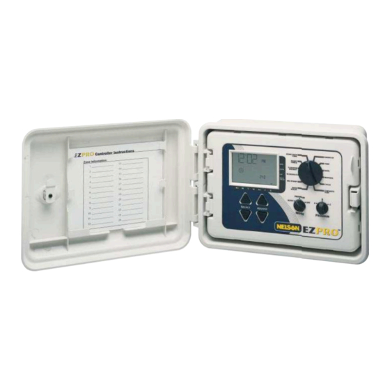
- Page 3 THANK YOU for purchasing the EZ Pro™ electronic irrigation controller. This controller offers great features in the standard models and the added full function radio capability in the "R" models. The EZ Pro™ is so "EZ", you’ll probably be able to install and program this feature-packed controller without instructions.
-
Page 4: Table Of Contents
TABLE OF CONTENTS Features Installation Terminal Strip Connecting Master Valve or Pump-Start Relay Connecting Rain/Moisture Sensor Connecting Battery & Resetting Controller Programming the EZ Pro™ 9-18 Programming Overview Front Panel Layout 10-11 Set Time of Day Set Today's Date Set Current Day... -
Page 5: Features
• EZ Command Radio Module is available factory installed in “R” models or can be added on later • Nelson exclusive Select and Adjust™ programming • Non-volatile memory stores programs without AC power or batteries • Pump Start programmable by zone •... -
Page 6: Installation
Use the supplied template to mark and pre-drill pilot holes in the wall. The middle two hole guides in the EZ Pro™ are vertically aligned for mounting the controller to a stud. (See Template) Insert screws through the holes in the case and screw each into the corresponding pilot hole in the wall. - Page 7 INSTALLATION INSTRUCTIONS For models 8604, 8606, 8608, 8612, 8616, 8620, 8624 (see figure 1) Remove the transformer cover by loosening the two screws. Attach AC wires to transformer wires using wire nuts. Also, ensure earth ground wire is attached to green with yellow stripe ground wire.
- Page 8 INSTALLATION INSTRUCTIONS For models 8674, 8676, 8678, 8682, 8686, 8690, 8694 (see figure 2) Remove the transformer cover by loosening the two screws. Route AC wires to connector provided. Cut and trim wires to install in chassis mount connector. Tighten the screws. (For Australia an extra clamp has been provided.) Observe proper polarity of wires as you install them (ie.
-
Page 9: Terminal Strip
All zone, pump and sensor wire connections made inside the EZ Pro™ utilize tool-less connectors. Pull the lever into the upper position and insert the wire into the bottom. Push the lever down to lock in the wire. The terminal strips in the EZ Pro™ controller accept 14 AWG (1.6mm) wire or smaller. -
Page 10: Connecting Battery & Resetting Controller
Europe) batteries to the battery clips and install the battery access door. The batteries enable the EZ Pro™ to be programmed without AC power and maintain the real time clock in the event of a power outage. If the batteries are not installed, the controller will lose real time in the event of a power outage. -
Page 11: Programming The Ez Pro
PROGRAMMING INSTRUCTIONS Programming Overview The EZ Pro™ can be programmed under AC power or powered from the two AA alkaline batteries. If equipped with an EZ Command Radio module the EZ Pro™ can be programmed from the EZ Command Remote Programmer. Before programming the EZ Pro™, it may be helpful to become familiar with some general programming guidelines: If a segment(s) on the LCD is flashing, it means that it can be changed by the user. -
Page 12: Front Panel Layout
Looking at the front panel (see figure 3), you see a large LCD, 4 rubber buttons, one large rotary dial, and two small rotary dials. The rubber buttons are marked SELECT and ADJUST and are the heart of Nelson’s exclusive SELECT&ADJUST™ programming. The keys are identified with for increasing or decreasing the segment you’re working on. - Page 13 PROGRAMMING INSTRUCTIONS FIGURE 3 NOTE: The MODE dial must be in the PROGRAM position. NOTE: Every time the key is pressed, the display will increase or decrease one unit. Hold the key for three seconds to initiate a fast scroll. NOTE: Please refer to the Technical Data section for an explanation of the LCD segments.
-
Page 14: Set Time Of Day
PROGRAMMING INSTRUCTIONS Set Time of Day Turn the large dial to the TIME position. Press SELECT to select between hours, minutes, and 12/24 hour mode. Press ADJUST to scroll to the correct time or adjust between 12/24 mode. Set Today’s Date and Current Day of the Week Turn the large dial to the DATE position. - Page 15 PROGRAMMING INSTRUCTIONS After the last zone and before the first zone, a RUN TIME summation is provided. This is useful for determining the total run time for a program. The LCD displays the letters "ALL" and a total RUN TIME is displayed. The time displayed is a summation of all the RUN TIMES for the selected program (100% water budget).
-
Page 16: Set Start Times
PROGRAMMING INSTRUCTIONS Set Start Times A START TIME is the time of day a program will start running. The EZ Pro™ allows four start times per program. Turn the large dial to the START TIMES position. Press SELECT to select the start time you want to set (1, 2, 3, or 4). -
Page 17: Set % Water Budget By Month
PROGRAMMING INSTRUCTIONS If % WATER BUDGET is set for 110% or greater, the EZ Pro™ will split the run time in half to reduce runoff. Half of the calculated run time will operate for each zone in that program, followed by the second half of the run time for each zone. -
Page 18: Set Water Days Scheduling Option
PROGRAMMING INSTRUCTIONS NOTE: The MODE dial must be in the PROGRAM position to set a schedule. The LCD will display the currently scheduled program (default is all WATER DAYS.) The SELECT keys will scroll the LCD display through each of the scheduling positions WATER DAYS, ODD, EVEN, INTERVAL, and INTERVAL START DATE. -
Page 19: Set Interval Scheduling Option
(can only be set up to 30 days out). Repeat the above procedures for each program (A, B, or C), as you require. That’s it! Your EZ Pro™ is now programmed. Turn the MODE dial to the AUTO position to run the program you entered. -
Page 20: Set Master Valve Or Pump
PROGRAMMING INSTRUCTIONS Set Master Valve or Pump You can turn on or off the Pump or Master valve output by zone with the EZ Pro™. Turn the large dial to the MV/PUMP position. Use the SELECT keys to choose the zone. Use the ADJUST to turn the MV/ PUMP output on or off when that zone is running. -
Page 21: Advanced Features
ADVANCED FEATURES The EZ Pro™ incorporates three manual/test procedures for checking the function of the controller or allowing you to bypass the current program to water immediately. The following section will show you how to set up the controller to: run a zone manually •... -
Page 22: Run A Program Cycle Manually
ADVANCED FEATURES The EZ Pro™ incorporates Nelson’s ManualAdvance™ feature in the MANUAL procedure. ManualAdvance™ allows you to cease the currently running zone and immediately advance to any new zone you select. With the MANUAL procedure running a zone, press SELECT to advance to a new zone. -
Page 23: Technical Data/Specifications
600 watts TVS across secondaries. (see Circuit Breaker below) 3. Sensor Operation The EZ Pro™ is configured to operate the controller with or without a sensor. Sensors must have normally closed connections (leads). The factory-installed jumper wire must be in place if no sensor is used. - Page 24 TECHNICAL DATA 6. Display EZ Pro ID, Time, Date, Start Time, Run Time, Program letter A, B or C Basic Date, Water Budget Month AM PM indicator Rain Sensor suspend watering symbol Even Year, Interval Days, Water Interval Budget, Zone number, Pump...
- Page 25 TECHNICAL DATA 10. Default Program 12:00 A.M. Sunday Date is 01/01 2000 No Run Times (zone 01, —:—) No Start Times (start number 01, —:—) 100% Water Budget Every day watering schedule Mode dial is at OFF position Program dial is on A program 5 second delay between zones (cannot be changed) 11.
-
Page 26: Troubleshooting/Service
BUDGET percentage Controller is not watering and RAIN • RAIN DELAY is programmed into EZ PRO • Turn large dial to RAIN DELAY position DELAY arrow appears on LCD and Mode dial to Program, check number of days on LCD. -
Page 27: Fcc Rules
FCC RULES This electronic irrigation controller generates and uses radio frequency energy and if not installed and used properly, that is, in strict accordance with the manufacturer’s instructions, may cause interference to radio and television reception. It has been type tested and found to comply with the limits for a Class B computing device in accordance with the specifications in Subpart J of Part 15 of FCC Rules, which are designed to provide reasonable protection against such interference in a residential installation. -
Page 28: Warranty
Fax (407) 648-0924 Nelson may, at its option, require that the product or part be returned to a Nelson service point or your retailer or distributor. Nelson will determine whether the claimed defect is covered by the warranty. If coverage is found, the product will be repaired or replaced. Please allow 4 to 6 weeks for completion of repairs or replacement and return of the product or part.