Siemens SENTRON 7KM Product Manual
Pac expansion module
Hide thumbs
Also See for SENTRON 7KM:
- Manual (224 pages) ,
- Configuration manual (80 pages) ,
- Instructions manual (76 pages)
Table of Contents
Advertisement
Quick Links
Advertisement
Table of Contents

Related Manuals for Siemens SENTRON 7KM


Summary of Contents for Siemens SENTRON 7KM
- Page 3 Introduction Description Installation Connection Commissioning Service and maintenance Equipment Manual Technical specifications Appendix 05/2020 L1V30408520AG-03...
- Page 4 Note the following: WARNING Siemens products may only be used for the applications described in the catalog and in the relevant technical documentation. If products and components from other manufacturers are used, these must be recommended or approved by Siemens. Proper transport, storage, installation, assembly, commissioning, operation and maintenance are required to ensure that the products operate safely and without any problems.
-
Page 5: Table Of Contents
Table of contents Introduction ............................5 Scope of delivery ......................... 5 Latest information ....................... 5 Security information ......................6 Open Source Software ......................7 Description ............................. 9 Area of application ....................... 9 Performance features of the I(N), I(Diff), analog module ............9 Design .......................... - Page 6 Table of contents Equipment Manual, 05/2020, L1V30408520AG-03...
-
Page 7: Introduction
• 1 x 7KM PAC expansion module I(N), I(Diff), analog • 1 x operating instructions Latest information Up-to-the-minute information You can find further support on the Internet: Website (https://support.industry.siemens.com/my/ww/en/requests) General safety information DANGER Hazardous voltage Will cause death or serious injury. -
Page 8: Security Information
To keep up to date with all the latest product updates, subscribe to the Siemens Industrial Security RSS Feed at (https://www.siemens.com/industrialsecurity). Equipment Manual, 05/2020, L1V30408520AG-03... -
Page 9: Open Source Software
Product or any OSS components contained in it if they are modified or used in any manner not specified by SIEMENS. The license conditions may contain disclaimers that apply between you and the respective licensor. -
Page 11: Description
Description Area of application The expansion module has been designed for use in combination with the 7KM PAC devices. The guidelines for the 7KM PAC devices also apply to the expansion module. When used in conjunction with 7KN POWERCENTER, powermanager and Cloud MindSphere, expansion module I(N), I(Diff), analog makes it possible to monitor measured quantities, such •... - Page 12 • Status indication via LED • When used in conjunction with a SENTRON 7KM PAC3220 or PAC4200 measuring device, the averaging of all measured values is possible in two stages, which are independent of each other and freely configurable (aggregation).
-
Page 13: Design
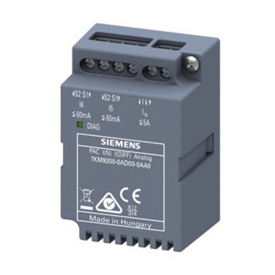
Description 2.3 Design Design Screw terminals for connection of current transformer or sensor Screw for mounting the expansion module I(N), I(Diff), analog Ventilation slot Diagnostic LED Figure 2-2 Schematic representation of expansion module I(N), I(Diff), analog connection: Current transformer connection for N-conductor current measurement 1 A / 5 A input connection: •... - Page 14 Description 2.3 Design Equipment Manual, 05/2020, L1V30408520AG-03...
-
Page 15: Installation
The expansion module is inserted in the appropriate slot labeled "MOD1" or "MOD2" on the rear panel of the SENTRON 7KM PAC measuring device. Note Only one expansion module of the type I(N), I(Diff), analog may be connected to the PAC measuring device. -
Page 16: Installation Steps
Installation 3.2 Installation steps Installation steps Install the expansion module before staring up the SENTRON device. NOTICE Damaged components must not be operated. CAUTION Electrostatic discharge The expansion modules contain electronic components that can be irreparably damaged by electrostatic discharge. When handling modules, make sure that all objects in the handling environment (persons, workstation and packaging) are properly grounded. -
Page 17: Connection
Connection Safety information DANGER Hazardous voltage. Failure to observe this notice will cause death, serious injury or property damage. Turn off and lock out all power supplying this equipment before working on this device. WARNING Some of the following tasks are carried out when hazardous voltage is present. For this reason, they must only be carried out by qualified personnel who are familiar with and follow the safety regulations and precautions. -
Page 18: Connections
Connection 4.2 Connections Connections Terminal labeling Figure 4-1 Terminal labeling with screw terminals Number Terminal Function k↑ Current transformer input for N-conductor measurement l↓ Current transformer input for N-conductor measurement S1↑ Summation current transformer input; analog input I S2↓ Summation current transformer input; analog input I S1↑... - Page 19 Connection 4.2 Connections The device can be connected for current measurement and/or use of the analog inputs I or a combination of both. The module must be individually configured to meet the requirements of the application. Current measurement using current transformers Figure 4-2 Possible connection type with three current transformers Use of the external current transformer makes it possible to measure higher residual currents...
- Page 20 Connection 4.2 Connections Figure 4-3 Possible connection type with three current transformers Use of the external current transformer makes it possible to measure higher system currents. Example: Using a 50/5 A current transformer results in a maximum measurable I(N) current in the system of 50/5*5 A = 50 A (sine with peak factor 1.41).
- Page 21 If the device is used in the UL market, the use of transformers with UL approval is required. input: A suitable current transformer must be used to measure the N-conductor current. The appropriate current transformer ratio must be set on the SENTRON 7KM PAC measuring device or powerconfig. Equipment Manual, 05/2020, L1V30408520AG-03...
- Page 22 4.2 Connections input: A suitable summation current transformer (type A or type B) must be used to measure the current. The input must be configured accordingly on the SENTRON 7KM PAC measuring device or powerconfig. input: A suitable summation current transformer (type A or type B) must be used to measure the current.
- Page 23 I analog inputs can also be used to measure analog signals (0 / 4 ... 20 mA). The inputs must be configured accordingly on the SENTRON 7KM PAC measuring device or powerconfig. A suitable sensor (0 / 4 ... 20 mA) must be used for this application. The inputs I and I passive.
- Page 24 Connection 4.2 Connections Note Refresh time The refresh time of the measured values can be up to 5 s. Equipment Manual, 05/2020, L1V30408520AG-03...
- Page 25 Connection 4.2 Connections Equipment Manual, 05/2020, L1V30408520AG-03...
-
Page 27: Commissioning
Commissioning Overview Requirements 1. The expansion module has already been installed. 2. The expansion module and the PAC device have been connected up correctly. Note Check the connections. Failure to connect up the device correctly can result in malfunctions and failure of the device. Before you start commissioning the device, check that all connections are correct. -
Page 28: Setting The Expansion Module Parameters
PAC device using the SENTRON "powerconfig" configuration software. The SENTRON powerconfig configuration software can be downloaded from the Industry Online Support website (https://support.industry.siemens.com/cs/at/en/view/63452759). Setting parameters on the PAC device In the menu "EXPANSION MODULES", call the "I(N) I(DIFF) ANALOG" that you want to configure and then select menu item "SETTINGS". - Page 29 Commissioning 5.2 Setting the expansion module parameters The I and I inputs of the module can be configured in the "SETTINGS" menu. Selection Function / value range ► Set the I input parameters ► Set the I input parameters ► Set the I input parameters ◄...
- Page 30 Commissioning 5.2 Setting the expansion module parameters Current example: Selection Function / value range Factory setting Residual current 100 mA / 500 = 0.2 mA (at module input) 100 mA: Residual current 3 3 A / 500 = 6 mA (at module input) Maximum measurable residual current with a 500/1 current transformer: 60 mA x 500 = 30 A Setting the ADC 0/4 - 20 mA parameters Selection...
-
Page 31: Parameterizing With Powerconfig
• Updating of device firmware and loading of language packs (device-dependent) You can download the powerconfig configuration software from the Industry Online Support Website (https://support.industry.siemens.com/cs/ww/en/view/63452759). Information and notes on how to use powerconfig can be found in the Online Help of the configuration software or by contacting Technical Support. -
Page 32: Reading Out Measured Values
Modbus command. The SENTRON powerconfig configuration software can be downloaded from the Industry Online Support website (https://support.industry.siemens.com/cs/ww/en/view/63452759). Reading out from PAC device In the menu "EXPANSION MODULES", call the "I(N) I(DIFF) ANALOG" from which you want to read measured values and then select menu item "MEASUREMENT". -
Page 33: Service And Maintenance
Firmware update The expansion module I(N), I(Diff) analog supports firmware updates. The latest firmware versions (https://support.industry.siemens.com/cs/ww/en/view/109756312) can be downloaded from the Service and Support Portal. Use the latest version of the SENTRON powerconfig configuration software to install updates. For update instructions, please see the related documentation and online help. -
Page 34: Warranty
The contents of this instruction manual shall not become part of or modify any prior or existing agreement, commitment, or relationship. The sales contract contains the entire obligation of Siemens. The warranty contained in the contract between the parties is the sole warranty of Siemens. Any statements contained herein do not create new warranties or modify the existing warranty. -
Page 35: Technical Specifications
Technical specifications Device configuration • I - measuring input • I - analog input • I - analog input Supply voltage No external supply voltage is required. The expansion module is supplied via the PAC device. Measuring inputs Connection to AC power systems is only possible via external current transformers. input Input current I 10 mA ... - Page 36 Technical specifications Connection elements Table 7- 1 Conductor cross-section Rigid 0.5 ... 4 22 ... 12 Flexible 0.5 ... 4 22 ... 12 Flexible with end sleeve, without plastic 0.5 ... 1.5 22 ... 16 sleeve Flexible with end sleeve and plastic sleeve 0.5 ...
- Page 37 You can find more information in the operating instructions and in the equipment manual for the SENTRON PAC3200 (https://support.industry.siemens.com/cs/ww/en/view/26504150), PAC3220 (https://support.industry.siemens.com/cs/ww/en/view/109767307) or PAC4200 (https://support.industry.siemens.com/cs/ww/en/view/34261595) Power Monitoring Device. Ambient conditions The device may only be operated within enclosed dry rooms. Temperature range Ambient temperature during operating phase -25 ...
- Page 38 Approvals for USA and Canada Products bearing this mark meet both Canadian (CSA) and American (UL) requirements. Product approval in the United Kingdom (United Kingdom Conformity Assessed) You can download the relevant certificates (https://support.industry.siemens.com/cs/ww/en/ps/7KM9200-0AD00-0AA0/cert) from the Siemens Support website. Equipment Manual, 05/2020, L1V30408520AG-03...
-
Page 39: Appendix
Appendix Modbus measured quantities with function codes 0x03 and 0x04 Depending on the device slot (MOD 1 or MOD 2), measured values can be read out of the following register addresses. Abbr. in the "Access" column Abbreviation Read; read access Write;... - Page 40 Appendix A.2 Average value quantities File Offset address Address Length Name Format Access (FC 0x14) FC 0x03 FC 0x04 30095 I4_MOD2 float 30097 I5_MOD2 float 30099 I6_MOD2 float 30345 max_I4_MOD1 float 30347 max_I5_MOD1 float 30349 max_I6_MOD1 float 30351 max_I4_MOD2 float 30353 max_I5_MOD2 float...
- Page 41 Appendix A.2 Average value quantities File Offset address Address Length Name Format Access (FC 0x14) FC 0x03 FC 0x04 30141 I6_MOD2 float 30331 max_I4_MOD1 float 30333 max_I5_MOD1 float 30335 max_I6_MOD1 float 30337 max_I4_MOD2 float 30339 max_I5_MOD2 float 30341 max_I6_MOD2 float 30531 min_I4_MOD1 float...
-
Page 43: Index
Index Ambient conditions Latest information, 5 Technical specifications, 35 Approvals Technical specifications, 36 Measuring inputs Technical specifications, 33 Calibration Service and maintenance, 31 Connection elements Open Source Software, 7 Technical specifications, 34 Use, 7 Connection examples, 16 Performance features Degree of protection and protection class Description, 10 Technical specifications, 35 Device configuration... - Page 44 Index Terminal labeling, 16 Troubleshooting guide Service and maintenance, 32 Warranty Service and maintenance, 32 Equipment Manual, 05/2020, L1V30408520AG-03...