
Related Manuals for Swann AMI Phosphate-II


Summary of Contents for Swann AMI Phosphate-II
- Page 1 A-96.250.641 / 290121 Operator’s Manual Firmware V6.20 and higher AMI Phosphate-II...
- Page 2 First release March 2012 AMI Phosphate-II B added Jan. 2013 Update to Firmware release 5.30 AMI Phosphate-II B with AMI Sample Sequencer Sep. 2013 Mainboard V2.4, FW update to V5.41 April 2017 Mainboard V2.5, FW update to V6.00, removed AMI Phosphate-II B July 2020 Mainboard V2.6...
-
Page 3: Table Of Contents
AMI Phosphate-II Table of Contents Safety Instructions .......... - Page 4 AMI Phosphate-II Maintenance ........... 37 6.1.
- Page 5 AMI Phosphate-II Default Values ..........83 Index .
-
Page 6: Safety Instructions
AMI Phosphate-II Safety Instructions AMI Phosphate-II–Operator’s Manual This document describes the main steps for instrument setup, opera- tion and maintenance. Safety Instructions General The instructions included in this section explain the potential risks associated with instrument operation and provide important safety practices designed to minimize these risks. -
Page 7: Warning Notices
AMI Phosphate-II Safety Instructions 1.1. Warning Notices The symbols used for safety-related notices have the following meaning: DANGER Your life or physical wellbeing are in serious danger if such warn- ings are ignored. Follow the prevention instructions carefully. WARNING Severe injuries or damage to the equipment can occur if such warnings are ignored. - Page 8 AMI Phosphate-II Safety Instructions Warning Signs The warning signs in this manual have the following meaning: Electrical shock hazard Corrosive Harmful to health Flammable Warning general Attention general A-96.250.641 / 290121...
-
Page 9: General Safety Regulations
AMI Phosphate-II Safety Instructions 1.2. General Safety Regulations Legal The user is responsible for proper system operation. All precautions must be followed to ensure safe operation of the instrument. Requirements Spare Parts Use only official SWAN spare parts and disposables. If other parts are used during the normal warranty period, the manufacturer’s war-... -
Page 10: Product Description
The AMI Phosphate-II is used in quality control of drinking water and waste water plants. Measuring The measurement is based on the molybdenum blue colorimetric method according to APHA 4500-P E. - Page 11 RS485 with Fieldbus protocol Modbus or Profibus DP HART interface Cleaning An optional cleaning module is available that can be connected to the AMI Phosphate-II. Module On-line The sample flows through the sample inlet [F] and the filter vessel [G] into the constant head [A].
- Page 12 AMI Phosphate-II Product Description 5 After the 7 min have elapsed a second measurement is carried out and the o-phosphate concentration is calculated. 6 If the measurement has been finished, the solenoid valve will be deactivated to open the inlet of the photometer.
-
Page 13: Instrument Specification
AMI Phosphate-II Product Description 2.1. Instrument Specification Power Supply AC variant: 100–240 VAC (± 10%) 50/60 Hz (± 5%) DC variant 10–36 VDC Power consumption: max. 35 VA Transmitter Housing: aluminum, with a protection degree of specifications IP 66 / NEMA 4X Ambient temperature: −10 to +50 °C... - Page 14 AMI Phosphate-II Product Description Dimensions Panel: Dimensions: 400x850x200 mm Screws: 5 mm or 6 mm diam. Weight: 9.5 kg /20.9 lbs 400 mm / 15.75" 374 mm / 14.72" Exit Enter AMI Phosphate-II 30 mm / 1.18" A-96.250.641 / 290121...
-
Page 15: Instrument Overview
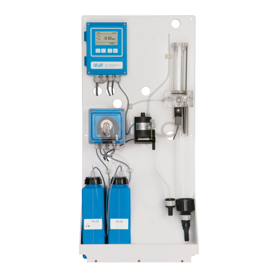
AMI Phosphate-II Product Description 2.2. Instrument Overview Panel PVC Photometer Transmitter Bubble detector Constant head Waste funnel for sample Air inlet pipe Drain Oxycon on-line Phosphate 1 Flow cell block Sample inlet with filter vessel Oxycon on-line Phosphate 2 Solenoid valve Peristaltic pump A-96.250.641 / 290121... -
Page 16: Installation
AMI Phosphate-II Installation Installation 3.1. Installation Check List On site require- AC variant: 100–240 VAC ( 10%), 50/60 Hz ( 5%) ments DC variant: 10–36 VDC Power consumption: 35 VA maximum. Protective earth connection required. Sample line with sufficient sample flow and pressure (see Instru- ment Specification, p. -
Page 17: Mounting Of Instrument Panel
AMI Phosphate-II Installation 3.2. Mounting of Instrument Panel The first part of this chapter describes the preparing and placing of the system for use. The instrument must only be installed by trained personnel. Mount the instrument in vertical position. -
Page 18: Connecting Sample And Waste
AMI Phosphate-II Installation 3.3. Connecting Sample and Waste Sample inlet Use plastic tube (FEP, PA, or PE 4 x 6 mm) to connect the sample line. Mounting of Screw connection SERTO fitting Compression ferrule Knurled nut Flexible tube Waste Connect the 1/2” tubes to the nozzle of the waste funnels and place them into an atmospheric drain of sufficient capacity. -
Page 19: Electrical Connections
AMI Phosphate-II Installation 3.4. Electrical Connections WARNING Risk of electrical shock. Do not perform any work on electrical components if the transmit- ter is switched on. Failure to follow safety instructions could result in serious injury or death. Always turn off power before manipulating electric parts. - Page 20 AMI Phosphate-II Installation WARNING External Voltage. External supplied devices connected to relay 1 or 2 or to the alarm relay can cause electrical shocks Make sure that the devices connected to the following contacts are disconnected from the power before resuming installation.
-
Page 21: Connection Diagram
AMI Phosphate-II Installation 3.4.1 Connection Diagram CAUTION Use only the terminals shown in this diagram, and only for the mentioned purpose. Use of any other terminals will cause short circuits with possible corresponding consequences to material and personnel. A-96.250.641 / 290121... -
Page 22: Power Supply
Mains cable to comply with standards IEC 60227 or IEC 60245; flammable rating FV1 Mains equipped with an external switch or circuit-breaker – near the instrument – easily accessible to the operator – marked as interrupter for AMI Phosphate-II A-96.250.641 / 290121... -
Page 23: Input
AMI Phosphate-II Installation 3.5. Input Note: Use only potential-free (dry) contacts. The total resistance (sum of cable resistance and resistance of the relay contact) must be less than 50 Ω. If signal output is set to hold, measurement is interrupted if input is active. -
Page 24: Relay Contacts 1 And 2
AMI Phosphate-II Installation 3.6.2 Relay Contacts 1 and 2 Note: Rated load 1 AT / 250 VAC Relay 1 and 2 can be configured as normally open or as normally closed. Standard for both relays is normally open. To configure a Re- lay as normally closed, set the jumper in the upper position. - Page 25 AMI Phosphate-II Installation CAUTION Risk of damage of the relays in the AMI Transmitter due to heavy inductive load. Heavy inductive or directly controlled loads (solenoid valves, dos- ing pumps) may destroy the relay contacts. To switch inductive loads > 0.1 A use an AMI relay box avail- able as an option or suitable external power relays.
-
Page 26: Signal Outputs
AMI Phosphate-II Installation 3.7. Signal Outputs 3.7.1 Signal Output 1 and 2 (current outputs) Note: Max. burden 510 Ω. If signals are sent to two different receivers, use signal isolator (loop isolator). Signal output 1: Terminals 14 (+) and 13 (-) -
Page 27: Signal Output 3
AMI Phosphate-II Installation 3.8.1 Signal Output 3 Terminals 38 (+) and 37 (-). Requires the additional board for the third signal output 0/4–20 mA. The third signal output can be operated as a current source or as a current sink (switchable via switch [A]). For detailed information see the corresponding installation instruction. -
Page 28: Hart Interface
AMI Phosphate-II Installation 3.8.3 HART Interface Terminals 38 (+) and 37 (-). The HART interface PCB allows for communication via the HART protocol. For detailed information, consult the HART manual. HART Interface PCB 3.8.4 USB Interface The USB Interface is used to store Logger data and for Firmware up- load. -
Page 29: Instrument Setup
AMI Phosphate-II Instrument Setup Instrument Setup After installation according to the checklist proceed as following: 1 Prepare reagents. See Refill or replace Reagents, p. 38 2 Insert suction lances 3 Lock the occlusion frames of the peristaltic pump. The peristaltic pump is ready. -
Page 30: Establish Sample Flow
AMI Phosphate-II Instrument Setup 4.1. Establish Sample Flow Cover Outer tube Flow cell block Flow regulating valve Filter Level Filter vessel 1 Turn on the sample flow. 2 Open the flow regulating valve (D). 3 Adjust the sample flow to about 10 l/h. -
Page 31: Fill Or Flush Reagent System
AMI Phosphate-II Instrument Setup 4.2. Fill or Flush Reagent System Fill or flush the reagent tubing: upon the initial instrument setup, after refilling the reagent containers, before a system shut-down to flush the system with demineral- ized water until no more reagent is left in the system. -
Page 32: Operation
AMI Phosphate-II Operation Operation 5.1. Function of the Keys Exit Enter to exit a menu or command (rejecting any changes) to move back to the previous menu level to move DOWN in a menu list and to decrease digits to move UP in a menu list and to increase digits... -
Page 33: Measured Values And Symbols On The Display
AMI Phosphate-II Operation 5.2. Measured Values and Symbols on the Display 15:20:18 0.52 23 B/s A RUN normal operation HOLD input closed or cal delay: Instrument on hold (shows status of signal outputs). input closed: Control/limit is interrupted (shows status of signal outputs). -
Page 34: Software Structure
AMI Phosphate-II Operation 5.3. Software Structure Main Menu Messages Diagnostics Maintenance Operation Installation Menu 1: Messages Messages Reveals pending errors as well as an event history Pending Errors (time and state of events that have occurred at an ear- Maintenance List lier point of time) and maintenance requests. -
Page 35: Changing Parameters And Values
AMI Phosphate-II Operation 5.4. Changing Parameters and Values Changing The following example shows how to change the logger interval: parameters 1 Select the parameter you want to Sensors Logger 5.1.2 4.4.1 change. Sensor type FOME Log interval 30 min 2 Press [Enter] Disinf. -
Page 36: Grab Sample
AMI Phosphate-II Operation Grab Sample Navigate to menu 4.1 <Operation/Grab Sample> and follow the dia- log on the Display. Relay status during <Grab Sample>: Signal outputs are on hold All limits are switched off 1 Navigate to menu <Operation>. -
Page 37: Maintenance
AMI Phosphate-II Maintenance Maintenance 6.1. Maintenance Schedule Daily (dirty water) Check sample supply for dirt. up to every Clean all filters and strainers, if necessary. 2 weeks (clean Check sample flow water) Monthly Recommendation: Check photometer with verification kit Verification, p. 40 Yearly Exchange reagent pump tubes. -
Page 38: Refill Or Replace Reagents
AMI Phosphate-II Maintenance 6.3. Refill or replace Reagents The liquid level in container 2 is monitored. The following message is displayed: Container almost Maintenance E065 - Reagents low and the empty remaining reagent volume in% (starting at 17% = 340ml). See Operation, p. - Page 39 AMI Phosphate-II Maintenance Preparation of Depending on the measuring interval the content of a Reagent Kid lasts for 6–18 Months OXYCON On-Line 1 graduated bucket 100 ml Phosphate No 1: 6 buckets with 20 g ammonium heptamolydate No 2: 6 buckets with 6 g potassium antimonyl (III) oxide tartrate...
-
Page 40: Verification
AMI Phosphate-II Maintenance General Fill the containers with 2 liters of demineralized water. Add the pre- scribed reagents and mix to complete dissolution. Reagent 1 First dissolve content of one bucket reagent 1. Only then measure 100 ml sulfuric acid and add carefully while gently mixing. - Page 41 AMI Phosphate-II Maintenance Verification Navigate to the menu 3.2.1 (Maintenance\Service\Verification) and follow the dialog on the screen. procedure Note: Start any time, if a measuring cycle is in progress wait for next prompt. 1 Stop sample flow by closing the flow regulating valve. Wait for next prompt: Constant head will be drained and an automatic zero will be defined.
-
Page 42: Calibration
AMI Phosphate-II Maintenance 6.5. Calibration 6.5.1 Prepare the Standard Solution To prepare the standard solution proceed as follows: 1 Put a pipette in the standard solution 1000 ppm 2 Fill the pipette with 1 ml of standard solution. 3 Put the pipette into a volumetric flask and empty it. -
Page 43: Process Calibration
AMI Phosphate-II Maintenance 6.6. Process Calibration The process calibration is based on a comparison measurement of the Instrument with an external high precision instrument. A process calibration can only be performed if the instrument has finished at least one valid measurement. -
Page 44: Cleaning The Protective Filter
AMI Phosphate-II Maintenance 6.7. Cleaning the protective Filter Switch off the instrument according to instructions in Stop of Opera- tion for Maintenance, p. Flow cell block Flow regulating valve Filter shaft Filter Filter vessel Normally the filter in your sample supply line will retain most debris. If the filter shows deposits, proceed as follows: 1 Close the main tap of the sample inlet. -
Page 45: Cleaning The Photometer
AMI Phosphate-II Maintenance 6.8. Cleaning the Photometer Clean the photometer after indication by alarm (E020, FOME dirty). Switch off the instrument according to instructions in Stop of Opera- tion for Maintenance, p. Material Small brush. Procedure Flow regulating valve Photometer cover... -
Page 46: Cleaning The Flow Cell
AMI Phosphate-II Maintenance 6.9. Cleaning the Flow Cell Because of using molybdenum, the flow cell block and the tubes will change color. Use 10% ammonia to remove the blue color. CAUTION Possible damage of acrylic glass parts due to scrubbing ma- terials. - Page 47 AMI Phosphate-II Maintenance Constant head cover Overflow tube Outer tube Flow cell block Flow regulating valve Level CAUTION Acrylic glass parts are fragile Handle with care. Cleaning 1 Switch off the instrument according to instructions in Stop of Op- eration for Maintenance, p.
-
Page 48: Assemble The Flow Cell
AMI Phosphate-II Maintenance 6.9.2 Assemble the Flow Cell Constant head cover Overflow tube Outer tube Gaskets Flow cell block Flow regulating valve Level 1 Replace all gaskets [D] before reassembling the flow cell. Note: A film of teflon paste (e.g. Fomblin from Solvay Solexis) on the gaskets improves tightness and life time. -
Page 49: Cleaning The Solenoid Valve
AMI Phosphate-II Maintenance 6.10. Cleaning the solenoid valve Disassemble The solenoid valve is mounted below the constant head. The sole- noid valve should be disassembled if it does not switch anymore or if the solenoid it is clogged. valve 1 Switch off the instrument according to instructions in Stop of Op- eration for Maintenance, p. - Page 50 AMI Phosphate-II Maintenance Note: The O-rings inside the valve body may stick on the flow cell and fall down if the valve body is removed. 5 Remove the valve body from the flow cell. 6 Remove the base plate (G) with a screw driver size 0 (F).
-
Page 51: Tube Replacement
AMI Phosphate-II Maintenance 6.11. Tube Replacement 6.11.1 Changing Pump Tubes The pump tubes [D] of the peristaltic pump are exposed to a minimal wear. It is therefore recommended to exchange the pump tubes an- nually. CAUTION Pollution of reagents possible. - Page 52 AMI Phosphate-II Maintenance Dismount The pump tubes can easily be dismounted and mounted. Proceed as follows: pump tubes Pump housing Occlusion frames relaxed Rotor Pump tubes Pump inlet Pump outlet 1 Switch off the instrument according to instructions in Stop of Op- eration for Maintenance, p.
-
Page 53: Tube Numbering
AMI Phosphate-II Maintenance 6.11.2 Tube Numbering Tube from Pump (C): rear frame, delivery side Flow cell (D), input 1 Pump (C): front frame, delivery side Flow cell (D), input 2 Reagent container (N) Pump (C): rear frame, suction side Oxycon on-line Phosphate Reagent 1... -
Page 54: Longer Stop Of Operation
AMI Phosphate-II Maintenance 6.12. Longer Stop of Operation 1 Switch off the instrument according to instructions in Stop of Op- eration for Maintenance, p. 37 2 Open pump tube assembly of Peristaltic pumps. See Changing Pump Tubes, p. 51 3 Empty the filter vessel. -
Page 55: Troubleshooting
AMI Phosphate-II Troubleshooting Troubleshooting 7.1. Error List Error Non-fatal Error. Indicates an alarm if a programmed value is exceed- ed. Such Errors are marked E0xx (bold and black). Fatal Error (blinking symbol) Control of dosing devices is interrupted. The indicated measured values are possibly incorrect. - Page 56 AMI Phosphate-II Troubleshooting Error Description Corrective action – check process E001 Phos. 1 Alarm high – check programmed value 5.3.1.1.1, p. 76 – check process E002 Phos. 1 Alarm low – check programmed value 5.3.1.1.25, p. 76 – check process E003 Phos.
- Page 57 AMI Phosphate-II Troubleshooting Error Description Corrective action – shut off power E019 FOME not connected – check wiring – clean photometer, see Cleaning the E020 FOME dirty Photometer, p. 45 – refill reagents, see Refill or replace Reagents, E022 Reagent empty p.
-
Page 58: Opening The Peristaltic Pump Housing
AMI Phosphate-II Troubleshooting 7.2. Opening the peristaltic pump housing For some electrical connections (e.g. when replacing suction lanc- es), it is necessary to open the housing of the peristaltic pump. To do this, proceed as follows: 1 Switch off the analyzer according to Stop of Operation for Mainte- nance, p. -
Page 59: Replacing Fuses
AMI Phosphate-II Troubleshooting 7.3. Replacing Fuses WARNING External Voltage. External supplied devices connected to relay 1 or 2 or to the alarm relay can cause electrical shocks. Make sure that the devices connected to the following contacts are disconnected from the power before resuming installation. -
Page 60: Program Overview
AMI Phosphate-II Program Overview Program Overview For explanations about each parameter of the menus see Program List and Explanations, p. 66 Menu 1 Messages informs about pending errors and mainte- nance tasks and shows the error history. Password protection possible. -
Page 61: Diagnostics (Main Menu 2)
AMI Phosphate-II Program Overview 8.2. Diagnostics (Main Menu 2) Identification AMI Phosphate-II * Menu numbers Desig. 2.1* Version V6.20 - 05/18 Peripherals 2.1.3.1* PeriClip 1 1.06 2.1.3* If cleaning Module is installed PeriClip 2 1.06 Factory Test 2.1.4.1* Instrument 2.1.4*... -
Page 62: Maintenance (Main Menu 3)
AMI Phosphate-II Program Overview 8.3. Maintenance (Main Menu 3) Calibration Calibration 3.1.5* * Menu numbers 3.1* Processcal. Processcal. 3.2.5* Service Verification (Progress) 3.3.1.5* 3.3* 3.3.1* Fill System (Progress) 3.3.2.5* 3.3.2* Simulation 3.4.1* Alarm Relay 3.4* 3.4.2* Relay 1 3.4.3* Relay 2 3.4.4*... -
Page 63: Operation (Main Menu 4)
AMI Phosphate-II Program Overview Fill Channel 11 3.6.2.5* * Menu numbers (Progress) 3.6.2* Fill Channel 12 3.6.3.5* (Progress) 3.6.3* 8.4. Operation (Main Menu 4) Grab Sample Grab Sample 4.1.5 4.1* Sensors 4.2.1* Filter Time Const. 4.2* 4.2.2* Hold after Cal. -
Page 64: Installation (Main Menu 5)
AMI Phosphate-II Program Overview 8.5. Installation (Main Menu 5) Sensors 5.1.1* * Menu numbers Ref. Verification 5.1* Phosphate as 5.1.2* 5.1.3* Standard PO4 5.1.4* Meas. Interval 5.1.5* Channels 5.1.6* Channel Selection Signal Outputs Signal Output 1 /2 Parameter 5.2.1.1/5.2.2.1* 5.2* 5.2.1* /5.2.2*... - Page 65 AMI Phosphate-II Program Overview Miscellaneous 5.4.1* * Menu numbers Language 5.4* 5.4.2* Set defaults 5.4.3* Load Firmware Password Messages 5.4.4.1* 5.4.4* 5.4.4.2* Maintenance 5.4.4.3* Operation 5.4.4.4* Installation 5.4.5* Sample ID Interface Protocol 5.5.1* (only with RS485 5.5* 5.5.21* interface) Device Address 5.5.31*...
-
Page 66: Program List And Explanations
AMI Phosphate-II Program List and Explanations Program List and Explanations 1 Messages 1.1 Pending Errors 1.1.5 Provides the list of active errors with their status (active, acknowl- edged). If an active error is acknowledged, the alarm relay is active again. Cleared errors are moved to the Message list. -
Page 67: Maintenance
AMI Phosphate-II Program List and Explanations 2.2.1.5 Ver. History: Review verifications values of the last verifications: 2.2.1.5.1 Number: Verification counter Date, Time: Date and time of verification Absorbance: Measured absorbance of the reference kit. Reference value: True value of the reference kit according to label. - Page 68 AMI Phosphate-II Program List and Explanations 3.2 Process cal. 3.2.5 Process calibration: The Process calibration is based on a comparison measurement of the Instrument wit an external high precision instrument, see Pro- cess Calibration, p. 3.3 Service 3.2.1 Verification: Performs a verification using the reference kit. Follow dialog.
- Page 69 AMI Phosphate-II Program List and Explanations 3.6 Cleaning Automatic cleaning process using the optional Cleaning Module-II. Cleaning is not possible if one of the following errors is active: E009/E010 Sample flow high/low E023 Cleaning solution 3.6.1 Parameters 3.6.1.1 Mode: The following modes can be chosen: interval, daily, weekly or off.
-
Page 70: Operation
AMI Phosphate-II Program List and Explanations If Mode = weekly The start of the automatic cleaning cycle can be set to one or more weekdays and any time of day. The programmed time of day is valid for all selected weekdays. -
Page 71: Installation
AMI Phosphate-II Program List and Explanations 4.4 Logger The instrument is equipped with an internal logger. The logger data can be copied to a PC with an USB stick if option USB interface is installed. The logger can save approx. 1500 data records. Records consists of: Date, time, alarms, measured value, measured value uncompensat- ed, temperature, flow. - Page 72 AMI Phosphate-II Program List and Explanations 5.2 Signal Outputs Note: The navigation in the menu <Signal Output 1> and <Signal Output 2> is equal. For reason of simplicity only the menu numbers of Signal Output 1 are used in the following.
- Page 73 AMI Phosphate-II Program List and Explanations [mA] 0 / 4 1’000 10’000 X Measured value (logarithmic) 5.2.1.40 Scaling: Enter beginning and end point (Range low & high) of the linear or logarithmic scale. In addition, the midpoint for the bilinear scale.
- Page 74 AMI Phosphate-II Program List and Explanations As control Signal outputs can be used for driving control units. We distinguish different kinds of controls: output P-controller: The controller action is proportional to the deviation from the setpoint. The controller is characterized by the P-Band.
- Page 75 AMI Phosphate-II Program List and Explanations Control upwards or downwards Setpoint: User defined precess value for the selected parameter. P-Band: Range below (upwards control) or above (downwards con- trol) the set-point, within which the dosing intensity is reduced from 100% to 0% to reach the set-point without overshooting.
- Page 76 AMI Phosphate-II Program List and Explanations 5.3.1.1.1 Alarm High: If the measured value rises above the alarm high value, the alarm relay is activated and E001 is displayed in the message list. Range: 0.00–10.00 ppm 5.3.1.1.25 Alarm Low: If the measured value falls below the alarm low value, the alarm relay is activated and E002 is displayed in the message list.
- Page 77 AMI Phosphate-II Program List and Explanations 5.3.2 and 5.3.3 Relay 1 and 2: The contacts can be set as normally open or normal- ly closed with a jumper. See Relay Contacts 1 and 2, p. 24. The func- tion of relay contacts 1 or 2 are defined by the user.
- Page 78 AMI Phosphate-II Program List and Explanations Actuator = Time proportional Examples of metering devices that are driven time proportional are solenoid valves, peristaltic pumps. Dosing is controlled by the operating time. 5.3.2.32.20 Cycle time: duration of one control cycle (on/off change).
- Page 79 AMI Phosphate-II Program List and Explanations 5.3.2.54 Delay: during run time plus the delay time the signal and control out- puts are held in the operating mode programmed below. Range: 0–6’000 Sec 5.3.2.6 Signal Outputs: select the behavior of the signal outputs when the re- lay closes.
- Page 80 AMI Phosphate-II Program List and Explanations 5.3.4.4 Fault: No message is issued in pending error list and the alarm relay does not close when input is active. Message E024 is stored in the message list. Message E024 is issued and stored in the message Yes: list.
- Page 81 AMI Phosphate-II Program List and Explanations 5.5 Interface Select one of the following communication protocols. Depending on your selection, different parameters must be defined. 5.5.1 Protocol: Profibus 5.5.20 Device address: Range: 0–126 5.5.30 ID-Nr.: Range: Analyzer; Manufacturer; Multivariable 5.5.40 Local operation: Range: Enabled, Disabled 5.5.1...
-
Page 82: Material Safety Data Sheets
AMI Phosphate-II Material Safety Data sheets Material Safety Data sheets 10.1. Reagents Catalogue No.: Included in A-85.420.660 Product name: OXYCON ON-LINE phosphate reagent 1 Catalogue No.: Included in A-85.420.660 Product name: OXYCON ON-LINE phosphate reagent 2 Catalogue No.: A-85.143.400 Product name:... - Page 83 AMI Phosphate-II Default Values Default Values Operation: Sensors: Filter Time Const.:................ 30 s Hold after Cal.:................300 s Alarm Relay .................same as in Installation Relay 1 and 2 .................same as in Installation Input .................same as in Installation Logger: Logger Interval:.............. Event-driven Clear Logger: ..................
- Page 84 AMI Phosphate-II Default Values If Function = Control upw. or dnw: Parameter:..............Phosphate 1 Settings: Actuator: ............Frequency Settings: Pulse Frequency: ..........120/min Settings: Control Parameters: Setpoint:......5.00 ppm Settings: Control Parameters: P-band: ......0.10 ppm Settings: Control Parameters: Reset time:........0 s Settings: Control Parameters: Derivative Time: ......0 s...
- Page 85 AMI Phosphate-II Index Index ......Alarm Relay occlusion frames ..
- Page 86 AMI Phosphate-II Index ......Verification history Wire ..
- Page 87 AMI Phosphate-II Notes Notes A-96.250.641 / 290121...
- Page 88 Swan Products - Analytical Instruments for: Swan is represented worldwide by subsidiary companies and distributors and cooperates with independent representatives all over the world. For contact in- formation, please scan the QR code. Swan Analytical Instruments ∙ CH-8340 Hinwil www.swan.ch ∙ swan@swan.ch AMI Phosphate-II...