Advertisement
Quick Links
INSTRUCTIONS MUST BE LEFT WITH THE OWNER FOR FUTURE REFERENCE AFTER INSTALLATION.
ATTENTION: It is recommended to install the blower assembly
before connecting gas inlet supply line.
WIRING
All wiring should be done by a qualified electrician and
shall be in compliance with all local, city and state building
codes. Before making the electrical connection, make sure
that main power supply is disconnected. The appliance,
when installed, must be electrically grounded in accordance
with local codes, with the National Electrical Code ANSI/
NFPA 70 (Latest Edition).
The appliance, when installed, must be electrically grounded in
accordance with local codes or, in the absence of local codes,
with the National Electrical Code, ANSI/NFPA 70, if an external
electrical source is utilized. This appliance is equipped with
a three-prong [grounding] plug for your protection against
shock hazard and should be plugged directly into a properly
grounded three-prong receptacle. Do not cut or remove the
grounding prong from this plug. For an ungrounded receptacle,
an adapter, which has two prongs and a wire for grounding, can be
purchased, plugged into the ungrounded receptacle and its wire
connected to the receptacle mounting screw. With this wire com-
pleting the ground, the appliance cord plug can be plugged into the
adapter and be electrically grounded.
Label all wires prior to disconnection when servicing controls.
Wiring errors can cause improper and dangerous operation.
Verify proper operation after servicing.
NOTICE: The junction box must be pre-wired at time of fireplace
installation for use with blower assembly. A standard wall ON/OFF
wall switch or optional SCV1 Variable Speed Control Kit should be
installed to activate power to the fireplace, and control the operation
of the FBB5 Blower assembly. It is recommended that installation
of the wiring be performed by a qualified electrician. See figure 1.
1.
If installed, turn OFF gas supply to firebox/gas log.
2.
If applicable, turn OFF electric supply to firebox.
33587-5-0820
INSTALLATION INSTRUCTIONS
FBB5 - 1 BLOWER KIT
CAUTION
CAUTION
Figure 1
Empire Comfort Systems Inc. • Belleville, IL
Page 1
Advertisement

Related Manuals for Empire Comfort Systems FBB5-1

Summary of Contents for Empire Comfort Systems FBB5-1
- Page 1 See figure 1. If installed, turn OFF gas supply to firebox/gas log. If applicable, turn OFF electric supply to firebox. Figure 1 33587-5-0820 Empire Comfort Systems Inc. • Belleville, IL Page 1...
-
Page 2: Table Of Contents
VFP(SB,PB) Firebox Blower Installation ..................5 - 6 VFP(SP,PP) Fireplace Blower Installation ................7 - 8 DVP(SP,PP) Fireplace Blower Installation ................9 - 10 Maintenance & Service Parts ...................... 11 How To Order Repair Parts ......................12 Page 2 Empire Comfort Systems Inc. • Belleville, IL 33587-5-0820... - Page 3 Figure 3 (Deluxe Flush shown) wires through the hole at the top of the firebox, and secure the fan control switch with the two screws provided. See Figure 6. Select Firebox Models 33587-5-0820 Empire Comfort Systems Inc. • Belleville, IL Page 3...
-
Page 4: Standard Firebox Blower Installation
11. To complete the installation, plug the power cord into the junction box receptacle at the right rear corner of the firebox outer wrap. See Figure 7. Page 4 Empire Comfort Systems Inc. • Belleville, IL 33587-5-0820... -
Page 5: Vfp(Sb,Pb) Firebox Blower Installation
Generally, it may take from 5 to 20 minutes to activate blower/fan control from a cold start. BLOWER AND JUNCTION BOX ACCESS COVER PLATE Figure 9 - Flush Face Models With Raised Hearth Extensions 33587-5-0820 Empire Comfort Systems Inc. • Belleville, IL Page 5... - Page 6 OPERATE OPTIONAL BLOWER FAN CONTROL SWITCH LOCATION Figure 10 WIRES FROM FAN Figure 12 CONTROL SWITCH HEARTH OUTER WRAP BLOWER ASSEMBLY (CENTER AND INSTALL AGAINST OUTER WRAP AS SHOWN) Figure 11 Page 6 Empire Comfort Systems Inc. • Belleville, IL 33587-5-0820...
-
Page 7: Vfp(Sp,Pp) Fireplace Blower Installation
(2) #6 screws (provided). The fan control wires will slide down between the firebox and outer wrap near the blower assembly. See Figure 14. 33587-5-0820 Empire Comfort Systems Inc. • Belleville, IL Page 7... - Page 8 CONTROL SWITCH HEARTH OUTER WRAP BLOWER ASSEMBLY (CENTER AND INSTALL AGAINST OUTER WRAP AS SHOWN) Figure 15 USE OF A STANDARD ON/OFF WALL SWITCH TO OPERATE OPTIONAL BLOWER Figure 16 Page 8 Empire Comfort Systems Inc. • Belleville, IL 33587-5-0820...
-
Page 9: Dvp(Sp,Pp) Fireplace Blower Installation
Generally, it may take from 10 to 20 minutes to activate firebox top. blower/fan control from a cold start. 33587-5-0820 Empire Comfort Systems Inc. • Belleville, IL Page 9... - Page 10 DVP(PP,SP) FIREPLACE BLOWER INSTALLATION FAN CONTROL SWITCH Figure 19 USE OF A STANDARD ON/OFF WALL SWITCH TO OPERATE OPTIONAL BLOWER Figure 20 Page 10 Empire Comfort Systems Inc. • Belleville, IL 33587-5-0820...
-
Page 11: Maintenance & Service Parts
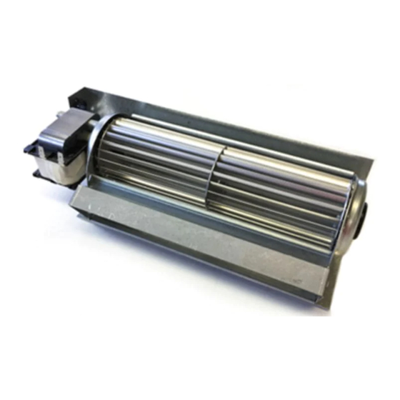
“OFF.” Figure 21 INDEX NO. PART NO. DESCRIPTION R7731 Blower Assembly R9901 Fan Control Switch R8147 Wire Assembly R7615 Cord Set R7891 Wire, Ground Figure 22 33587-5-0820 Empire Comfort Systems Inc. • Belleville, IL Page 11... -
Page 12: How To Order Repair Parts
Do not order bolts, screws, washers or nuts. They are standard hardware items and can be purchased at any local hardware store. Shipments contingent upon strikes, fires and all causes beyond our control. Empire Comfort Systems Inc. Belleville, IL If you have a general question about our products, please e-mail us at info@empirecomfort.com.