Table of Contents
Advertisement
Quick Links
Advertisement
Table of Contents

Related Manuals for Fortinet FortiGate-6000F Series


Summary of Contents for Fortinet FortiGate-6000F Series
- Page 1 FortiGate-6000F System Guide FortiGate-6000F Series...
- Page 2 FORTINET DOCUMENT LIBRARY https://docs.fortinet.com FORTINET VIDEO GUIDE https://video.fortinet.com FORTINET BLOG https://blog.fortinet.com CUSTOMER SERVICE & SUPPORT https://support.fortinet.com FORTINET TRAINING & CERTIFICATION PROGRAM https://www.fortinet.com/support-and-training/training.html NSE INSTITUTE https://training.fortinet.com FORTIGUARD CENTER https://fortiguard.com/ END USER LICENSE AGREEMENT https://www.fortinet.com/doc/legal/EULA.pdf FEEDBACK techdoc@fortinet.com Email: January 21, 2021 FortiGate-6000F 6.4.2 System Guide...
-
Page 3: Table Of Contents
Getting started with FortiGate-6000 Confirming startup status Default VDOM configuration and configuring the management interfaces Changing data interface network settings Adding a password to the admin administrator account Resetting to factory defaults Restarting the FortiGate-6000 FortiGate-6000F System Guide Fortinet Technologies Inc. - Page 4 Fortinet Technologies Inc. Managing individual FortiGate-6000 management boards and FPCs Special management port numbers HA mode special management port numbers Connecting to individual FPC consoles Connecting to individual FPC CLIs Performing other operations on individual FPCs Firmware upgrades Firmware upgrade basics Installing firmware on an individual FPC Installing firmware from the BIOS after a reboot...
-
Page 5: Change Log
Change log Fortinet Technologies Inc. Change log Date Change description January 21, 2021 Added information about FortiGate-6000F hardware generation 1 and generation 2, FortiGate-6000F hardware generations on page January 14, 2021 Updates and corrections to FortiGate-6000F AC power supply units (PSUs) on page 17. -
Page 6: Fortigate-6000F Hardware Description
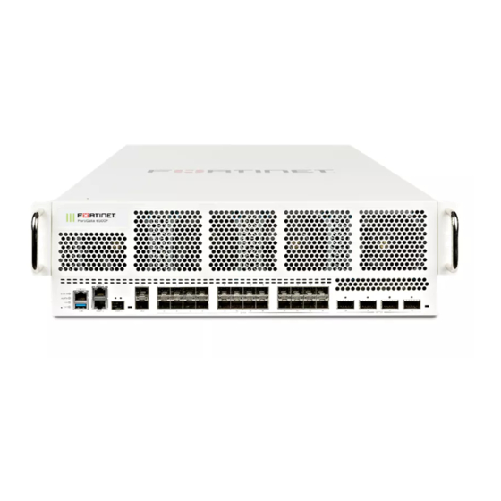
Fortinet Technologies Inc. FortiGate-6000F hardware description The FortiGate-6000F series is a collection of 3U 19-inch rackmount appliances that include twenty-four 1/10/25GigE SFP28 and four 40/100GigE QSFP28 data network interfaces, as well as NP6 and CP9 processors to deliver high IPS/threat prevention performance. -
Page 7: Front Panel Interfaces
FortiGate-6000F hardware description Fortinet Technologies Inc. Front panel interfaces All FortiGate-6000F models have the following front panel interfaces: Twenty-four 1/10/25GigE SFP28 data network interfaces (1 to 24). The default speed of these interfaces is 10Gbps. These interfaces are divided into the following interface groups: 1 - 4, 5 - 8, 9 - 12, 13 - 16, 17 - 20, and 21 - 24. -
Page 8: Front Panel Leds
FortiGate-6000F hardware description Fortinet Technologies Inc. set speed 25000full next edit port13 set speed 25000full next edit port17 set speed 25000full next edit port21 set speed 25000full Front panel LEDs State Description The FortiGate-6000F is powered off. Green The FortiGate-6000F is powered on and operating normally. -
Page 9: Front Panel Connectors
FortiGate-6000F hardware description Fortinet Technologies Inc. State Description No link is established. Green This interface is connected at 100Gbps /40Gbps with the correct cable and the attached network device has power. 25 to 28 Flashing Network traffic on this interface. -
Page 10: Supported Transceivers
USB 3.0 USB 3.0 Standard USB connector. Type A USB 2.0 Supported transceivers Transceivers available from Fortinet for the FortiGate-6000F 1 to 24 SFP28 interfaces. Transceiver Description FG-TRAN-GC 1GE SFP RJ45 transceiver. FG-TRAN-SX 1GE SFP transceiver module, short range. -
Page 11: Console Port
10GE SFP+ transceiver module, long range. FG-TRAN-SFP28-SR 25GE SFP28 transceiver module, short range. FG-TRAN-SFP28-LR 25GE SFP28 transceiver module, long range. Transceivers available from Fortinet for the FortiGate-6000F 25 to 28 QSP28 interfaces. Transceiver Description FG-TRAN-QSFP28-SR4 100GBase-SR4 QSFP28 transceiver, short range. -
Page 12: Connecting To The Cli Of An Individual Fpc
6. When your session is complete, enter the exit command to log out. NMI switch and NMI reset commands When working with Fortinet Support to troubleshoot problems with your FortiGate-6000F you can use the front panel non-maskable interrupt (NMI) switch to assist with troubleshooting. Pressing this switch causes the software to dump management board registers/backtraces to the console. -
Page 13: Fortigate-6000F Back Panel
In the data plane, two DP3 load balancers use session-aware load balancing to distribute sessions from the front panel interfaces (port1 to 28) to Fortinet Processor Cards (FPCs). The DP3 processors communicate with the FPCs across the 3.2Tbps integrated switch fabric. Each FPC processes sessions load balanced to it. The FPCs send outgoing sessions back to the integrated switch fabric and then out the network interfaces to their destinations. - Page 14 12xKR Base Backplane Integrated Switch Fabric (3.2 Tbps) (Data Plane) (Management Plane) 6xKR 6xKR Management Board Fortinet Processor Card (FPC) 4x XAUI Fortinet Processor Card (FPC) 4x XAUI FortiGate-6500 = 10x FPCs FortiGate-6300 = 6x FPCs FortiGate-6000F 6.4.2 System Guide...
-
Page 15: Fortigate-6000F Hardware Information
FortiGate-6000F hardware description Fortinet Technologies Inc. FortiGate-6000F hardware information This section introduces FortiGate-6000F hardware components and accessories. Shipping components The FortiGate-6000F ships pre-assembled with the following components: The 3U FortiGate-6000F. The AC version of the FortiGate-6000F includes three AC Power Supply Units (PSUs) installed in the back panel. -
Page 16: Fortigate-6000F Hardware Generations
FPCs. For more information on FortiGate-6000F generation 1 and generation 2, including supported firmware versions and how to determine the generation of your FortiGate-6000F hardware, see the Fortinet Knowledge base article: Technical Tip: Information on FortiGate-6000F series Gen1 and Gen2... -
Page 17: Fortigate-6000F Ac Power Supply Units (Psus)
FortiGate-6000F hardware description Fortinet Technologies Inc. Cooling Fan Tray Handle Retention Retention Screw Screw Retention Retention Screw Screw Fan trays are hot swappable. You can replace a failed fan tray while the FortiGate-6000F is operating. To replace a fan tray, unscrew the four retention screws and use the handle to pull the fan tray out of the chassis. Install the new fan tray by sliding it into place. -
Page 18: Connecting Generation 2 Fortigate-6000F Psus To High Line Ac Power
Fortinet Technologies Inc. For more information on FortiGate-6000F generation 1 and generation 2, including supported firmware versions and how to determine the generation of your FortiGate-6000F hardware, see the Fortinet Knowledge base article: Technical Tip: Information on FortiGate-6000F series Gen1 and Gen2... -
Page 19: Connecting Generation 1 Or 2 Fortigate-6000F Psus To Low Line Ac Power
FortiGate-6000F hardware description Fortinet Technologies Inc. Connecting generation 1 or 2 FortiGate-6000F PSUs to low line AC power If you connect a generation 1 FortiGate-6000F or a generation 2 FortiGate-6000F PSU to low line AC power, each PSU provides 1500W AC and at least two PSUs (PSU1 and PSU2) must be connected to power. PSU3 is a backup PSU and provides 2+1 redundancy. -
Page 20: Connecting Fortigate-6000F Psus To Ac Power
FortiGate-6000F hardware description Fortinet Technologies Inc. State Description Flashing amber Warning that power input or output is close to outside of normal operating range. PSU should be replaced. Connecting FortiGate-6000F PSUs to AC power Use the following steps to connect a FortiGate-6000F PSU to AC power after connecting the chassis to ground. - Page 21 FortiGate-6000F hardware description Fortinet Technologies Inc. To connect the FortiGate-6000F chassis to ground Data Center FortiGate-6000F ground Ground connector Connector (Central office ground system) 1. Attach the ESD wrist strap to your wrist and to an ESD socket or to a bare metal surface on the FortiGate-6000F.
-
Page 22: Fortigate-6000F Hardware Assembly And Rack Mounting
FortiGate-6000F hardware assembly and rack mounting Fortinet Technologies Inc. FortiGate-6000F hardware assembly and rack mounting The FortiGate-6000F appliance can be mounted in a standard 19-inch rack and requires 3U of vertical space in the rack. The FortiGate-6000F can also be surface mounted. -
Page 23: Fortigate-6000F Four Post Rack-Mount Installation
FortiGate-6000F hardware assembly and rack mounting Fortinet Technologies Inc. FortiGate-6000F four post rack-mount installation This section describes how to use the sliding rails included with your FortiGate-6000F package to install the FortiGate- 6000F in a 4-post rack. The FortiGate-6000F is shipped with a left and a right rail assembly. Each rail assembly includes an inner rail, a middle rail, and an outer rail. - Page 24 FortiGate-6000F hardware assembly and rack mounting Fortinet Technologies Inc. Tabs, holes, and clips on the right inner rail Lock out tab Release tab Holes Metal clip System release buttons Attaching the inner rails to the FortiGate-6000F Use the following steps to install the right inner rail and then repeat them for the left inner rail.
-
Page 25: Sliding The Fortigate-6000F Into The Rack
FortiGate-6000F hardware assembly and rack mounting Fortinet Technologies Inc. 6. Slide the inner rail towards the front of the FortiGate-6000F until the inner rail metal clip clicks, locking the rail onto the side of the FortiGate-6000F. 7. Repeat these steps to attach the left inner rail to the left side of the FortiGate-6000F. - Page 26 FortiGate-6000F hardware assembly and rack mounting Fortinet Technologies Inc. 3. Pull the middle rails out from the front of the outer rails until they lock into place. 4. Use a lifting device to raise the FortiGate-6000F to allow you to align the inner rails with the middle rails.
-
Page 27: Removing The Fortigate-6000F From A Four-Post Rack
FortiGate-6000F hardware assembly and rack mounting Fortinet Technologies Inc. System release buttons Removing the FortiGate-6000F from a four-post rack Make sure that a lifting device is available to slide the FortiGate-6000F on to when removing it from the rack. You will need a screwdriver to remove the four rack screws. -
Page 28: Surface-Mount Installation
FortiGate-6000F hardware assembly and rack mounting Fortinet Technologies Inc. Middle Rail Latch 8. Push the metal clip on each inner rail toward the front of the FortiGate-6000F to release the inner rails from the hooks on the side of the FortiGate-6000F and remove the inner rails. -
Page 29: To Install Transceivers
FortiGate-6000F hardware assembly and rack mounting Fortinet Technologies Inc. To install transceivers To complete this procedure, you need: A FortiGate-6000F Transceivers to install An electrostatic discharge (ESD) preventive wrist strap with connection cord FortiGate-6000Fs must be protected from static discharge and physical shock. Only handle or work with FortiGate-6000Fs at a static-free workstation. -
Page 30: Getting Started With Fortigate-6000
All configuration changes must be made from the management board GUI or CLI and not from individual FPCs. All other management communication (for example, SNMP queries, remote logging, and so on) use the MGMT1 or MGMT2 interfaces and are handled by the management board. FortiGate-6000F 6.4.2 System Guide Fortinet Technologies Inc. -
Page 31: Confirming Startup Status
Getting started with FortiGate-6000 Fortinet Technologies Inc. Confirming startup status Before verifying normal operation and making configuration changes and so on you should wait until the FortiGate-6000 is completely started up and synchronized. This can take a few minutes. Dashboard > Cluster Status . If the system is synchronized,... -
Page 32: Changing Data Interface Network Settings
Getting started with FortiGate-6000 Fortinet Technologies Inc. and so on. You can also add VLANs to the interfaces in mgmt-vdom and create a LAG that includes the mgmt1 and mgmt2 interfaces. You can use the root VDOM for data traffic and you can also add more VDOMs as required, depending on your Multi VDOM license. -
Page 33: Restarting The Fortigate-6000
Getting started with FortiGate-6000 Fortinet Technologies Inc. Restarting the FortiGate-6000 To restart the FortiGate-6000, connect to the management board CLI and enter the execute reboot command. After you enter this command, the management board and all of the FPCs restart. -
Page 34: Managing Individual Fortigate-6000 Management Boards And Fpcs
You can't change the special management port numbers. Changing configurable management port numbers, for example the HTTPS management port number (which you might change to support SSL VPN), does not affect the special management port numbers. FortiGate-6000F 6.4.2 System Guide Fortinet Technologies Inc. -
Page 35: Ha Mode Special Management Port Numbers
Managing individual FortiGate-6000 management boards and FPCs Fortinet Technologies Inc. FortiGate-6000 special management port numbers Slot Address HTTP HTTPS (443) Telnet SSH (22) SNMP (161) (80) (23) Slot 0, (MBD) 8000 44300 2300 2200 16100 Slot 1 (FPC01) 8001 44301... -
Page 36: Connecting To Individual Fpc Consoles
Managing individual FortiGate-6000 management boards and FPCs Fortinet Technologies Inc. Slot Address HTTP HTTPS (443) Telnet SSH (22) SNMP (161) (80) (23) Slot 1 (FPC01) 8021 44321 2321 2221 16121 Slot 2 (FPC02) 8022 44322 2322 2222 16122 Slot 3 (FPC03) -
Page 37: Connecting To Individual Fpc Clis
Managing individual FortiGate-6000 management boards and FPCs Fortinet Technologies Inc. In an HA configuration, the execute system console-server commands only allow access to FPCs in the FortiGate-6000 that you are logged into. You can't use this command to access FPCs in the other FortiGate-6000 in an HA cluster... -
Page 38: Firmware Upgrades
DP3 processor is included. Before beginning a firmware upgrade, Fortinet recommends that you perform the following tasks: Review the latest release notes for the firmware version that you are upgrading to. -
Page 39: Installing Firmware From The Bios After A Reboot
CLI of the FPC and restart it using the execute reboot command. If this does not solve the problem, contact Fortinet Support at https://support.fortinet.com The example output also shows that the uptime of the FPC in slot 3 is lower than the uptime of the other FPCs, indicating that the FPC in slot 3 has recently restarted. - Page 40 Firmware upgrades Fortinet Technologies Inc. Installing or upgrading FortiGate-6000 firmware from the BIOS after a reboot installs firmware on and resets the configuration of the management board only. FPCs will continue to operate with their current configuration and firmware build. The FortiGate-6000 system does not synchronize firmware upgrades that are performed from the BIOS.
-
Page 41: Synchronizing The Fpcs With The Management Board
Firmware upgrades Fortinet Technologies Inc. Synchronizing the FPCs with the management board After you install firmware on the management board from the BIOS after a reboot, the firmware version and configuration of the management board will most likely not be synchronized with the FPCs. You can verify this from the management board CLI using the diagnose sys confsync status | grep in_sy command. - Page 42 Firmware upgrades Fortinet Technologies Inc. F6KF31T018900143, Master, uptime=3837.25, priority=1, slot_id=1:0, idx=0, flag=0x0, in_sync=1 FPC6KFT018901574, Slave, uptime=3774.19, priority=22, slot_id=1:4, idx=1, flag=0x4, in_sync=1 F6KF31T018900143, Master, uptime=3837.25, priority=1, slot_id=1:0, idx=0, flag=0x0, in_sync=1 FPC6KFT018901345, Slave, uptime=3773.59, priority=23, slot_id=1:5, idx=1, flag=0x4, in_sync=1 F6KF31T018900143, Master, uptime=3837.25, priority=1, slot_id=1:0, idx=0, flag=0x0, in_sync=1 FPC6KFT018901556, Slave, uptime=3774.82, priority=24, slot_id=1:6, idx=1, flag=0x4, in_sync=1...
-
Page 43: Cautions And Warnings
Blade Carriers, Cards and Modems must be Listed Accessories or Switch, Processor, Carrier and similar blades or cards should be UL Listed or Equivalent. Serveur-blades, cartes et modems doivent être des accessoires listés ou commutateurs, processeurs, serveurs et similaire blades ou cartes doivent être listé UL ou équivalent. FortiGate-6000F 6.4.2 System Guide Fortinet Technologies Inc. -
Page 44: Safety
Cautions and warnings Fortinet Technologies Inc. Refer to specific Product Model Data Sheet for Environmental Specifications (Operating Temperature, Storage Temperature, Humidity, and Altitude). Référez à la Fiche Technique de ce produit pour les caractéristiques environnementales (Température de fonctionnement, température de stockage, humidité et l'altitude). - Page 45 Cautions and warnings Fortinet Technologies Inc. ATTENTION: Risque d'électrocution. Débranchez toutes les sources d'alimentation. Grounding - To prevent damage to your equipment, connections that enter from outside the building should pass through a lightning / surge protector, and be properly grounded. Use an electrostatic discharge workstation (ESD) and/or wear an anti-static wrist strap while you work.
-
Page 46: Regulatory Notices
European Conformity (CE) - EU This is a Class A product. In a domestic environment, this product may cause radio interference, in which case the user may be required to take adequate measures. FortiGate-6000F 6.4.2 System Guide Fortinet Technologies Inc. -
Page 47: Voluntary Control Council For Interference (Vcci) - Japan
Regulatory notices Fortinet Technologies Inc. Voluntary Control Council for Interference (VCCI) – Japan こ の装 置 は、 ク ラ スA 機 器 です。 こ の装 置 を住 宅 環 境 で使 用 すると 電 波 妨 害 を引 き起 こ すこ と があり ます。 こ の場 合 には使... - Page 48 Copyright© 2021 Fortinet, Inc. All rights reserved. Fortinet®, FortiGate®, FortiCare® and FortiGuard®, and certain other marks are registered trademarks of Fortinet, Inc., in the U.S. and other jurisdictions, and other Fortinet names herein may also be registered and/or common law trademarks of Fortinet. All other product or company names may be trademarks of their respective owners.